EP1547873A2 - Überrollschutzsystem für Kraftfahrzeuge mit einem ausfahrbaren Überrollkörper - Google Patents
Überrollschutzsystem für Kraftfahrzeuge mit einem ausfahrbaren Überrollkörper Download PDFInfo
- Publication number
- EP1547873A2 EP1547873A2 EP04022126A EP04022126A EP1547873A2 EP 1547873 A2 EP1547873 A2 EP 1547873A2 EP 04022126 A EP04022126 A EP 04022126A EP 04022126 A EP04022126 A EP 04022126A EP 1547873 A2 EP1547873 A2 EP 1547873A2
- Authority
- EP
- European Patent Office
- Prior art keywords
- rollover
- vehicle
- protection system
- holding device
- compression spring
- Prior art date
- Legal status (The legal status is an assumption and is not a legal conclusion. Google has not performed a legal analysis and makes no representation as to the accuracy of the status listed.)
- Granted
Links
Images

Classifications
-
- F—MECHANICAL ENGINEERING; LIGHTING; HEATING; WEAPONS; BLASTING
- F15—FLUID-PRESSURE ACTUATORS; HYDRAULICS OR PNEUMATICS IN GENERAL
- F15B—SYSTEMS ACTING BY MEANS OF FLUIDS IN GENERAL; FLUID-PRESSURE ACTUATORS, e.g. SERVOMOTORS; DETAILS OF FLUID-PRESSURE SYSTEMS, NOT OTHERWISE PROVIDED FOR
- F15B15/00—Fluid-actuated devices for displacing a member from one position to another; Gearing associated therewith
- F15B15/20—Other details, e.g. assembly with regulating devices
- F15B15/26—Locking mechanisms
- F15B15/261—Locking mechanisms using positive interengagement, e.g. balls and grooves, for locking in the end positions
-
- B—PERFORMING OPERATIONS; TRANSPORTING
- B60—VEHICLES IN GENERAL
- B60R—VEHICLES, VEHICLE FITTINGS, OR VEHICLE PARTS, NOT OTHERWISE PROVIDED FOR
- B60R21/00—Arrangements or fittings on vehicles for protecting or preventing injuries to occupants or pedestrians in case of accidents or other traffic risks
- B60R21/02—Occupant safety arrangements or fittings, e.g. crash pads
- B60R21/13—Roll-over protection
-
- F—MECHANICAL ENGINEERING; LIGHTING; HEATING; WEAPONS; BLASTING
- F15—FLUID-PRESSURE ACTUATORS; HYDRAULICS OR PNEUMATICS IN GENERAL
- F15B—SYSTEMS ACTING BY MEANS OF FLUIDS IN GENERAL; FLUID-PRESSURE ACTUATORS, e.g. SERVOMOTORS; DETAILS OF FLUID-PRESSURE SYSTEMS, NOT OTHERWISE PROVIDED FOR
- F15B15/00—Fluid-actuated devices for displacing a member from one position to another; Gearing associated therewith
- F15B15/19—Pyrotechnical actuators
-
- F—MECHANICAL ENGINEERING; LIGHTING; HEATING; WEAPONS; BLASTING
- F15—FLUID-PRESSURE ACTUATORS; HYDRAULICS OR PNEUMATICS IN GENERAL
- F15B—SYSTEMS ACTING BY MEANS OF FLUIDS IN GENERAL; FLUID-PRESSURE ACTUATORS, e.g. SERVOMOTORS; DETAILS OF FLUID-PRESSURE SYSTEMS, NOT OTHERWISE PROVIDED FOR
- F15B15/00—Fluid-actuated devices for displacing a member from one position to another; Gearing associated therewith
- F15B15/20—Other details, e.g. assembly with regulating devices
- F15B15/26—Locking mechanisms
- F15B15/262—Locking mechanisms using friction, e.g. brake pads
-
- B—PERFORMING OPERATIONS; TRANSPORTING
- B60—VEHICLES IN GENERAL
- B60R—VEHICLES, VEHICLE FITTINGS, OR VEHICLE PARTS, NOT OTHERWISE PROVIDED FOR
- B60R21/00—Arrangements or fittings on vehicles for protecting or preventing injuries to occupants or pedestrians in case of accidents or other traffic risks
- B60R21/02—Occupant safety arrangements or fittings, e.g. crash pads
- B60R21/13—Roll-over protection
- B60R2021/132—Roll bars for convertible vehicles
- B60R2021/134—Roll bars for convertible vehicles movable from a retracted to a protection position
- B60R2021/135—Roll bars for convertible vehicles movable from a retracted to a protection position automatically during an accident
Definitions
- the invention relates to a rollover protection system for motor vehicles, with a movable in a vehicle-fixed leadership held rollover body in the normal state against the force of at least one biased drive compression spring by a Retaining device is durable in a lower, retracted rest position, and releasing the holding device by the spring force of the drive compression spring can be brought into a locked upper, protective position, wherein the holding device connected to the rollover body Holding member and thus a releasable mechanical operative connection standing trigger member on a vehicle-mounted, sensor-controlled having pyrotechnic actuator.
- Such rollover protection systems serve to protect the occupants in Motor vehicles without a protective roof, typically in cabriolets or sports car in a rollover, as the vehicle over the Roll over roll body.
- These rollover protection systems typically have one in one vehicle-fixed guide body guided U-shaped or made of a Profile body formed rollover body, on, wherein the guide body in a cassette housing is attached.
- This rollover will be in Normal state against the biasing force of a drive compression spring held by a holding device in a lower rest position, and is in the rollover case, sensor-controlled with release of the holding device, by the spring force of the drive compression spring in an upper, protective Position can be brought, wherein a then entering into operative engagement locking device, the re-entry lock, an impression of the roll bar prevented.
- each vehicle seat is one Assigned cassette, especially in the front vehicle seats. In the rear, the cassettes can also be used in a rear wall unit be integrated.
- Such a cassette construction of a roll bar protection system for example, with a U-shaped roll bar DE 43 42 400 A1; an alternative cassette construction with a Rollover body in the form of a profile body shows in particular the DE 198 38 989 C1.
- the aforementioned holding device for the extendable rollover body typically has a retaining member attached to the rollover body, the in releasable mechanical operative connection with a trigger member a vehicle-mounted, sensor-controlled release system, the Actuator, standing by a trigger magnet, the so-called Crash magnets, or by a pyrotechnic trigger member formed is.
- the retaining member is useful in many constructions, e.g. according to DE 100 12 573 C1, designed as a retaining bolt, which is e.g.
- the invention is based on the object designated at the beginning Rollover protection system with respect to the holding device in such a way that no pawls are used and on structurally simple A safe hold and release is guaranteed.
- a rollover protection system for Motor vehicles with a movable in a vehicle-fixed leadership held rollover body in the normal state against the force of at least one biased drive compression spring by a Retaining device is durable in a lower, retracted rest position, and releasing the holding device by the spring force of the drive compression spring can be brought into a locked upper, protective position, wherein the holding device connected to the rollover body Holding member and thus a releasable mechanical operative connection standing trigger member on a vehicle-mounted, sensor-controlled pyrotechnic trip unit, according to the invention in that the trigger member with the associated pyrotechnic Tripping unit is formed by a pyromechanical separating element, which consists of two parts, of which the first part is an electric one contains ignitable pyrotechnic propellant, and of which the second part via a locking ring positive and positive separably communicating with the first part, being one part vehicle-mounted and the other part is firmly attached to the holding member connected is.
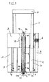
- FIGS 1 - 3 show in different views and Operating conditions a rollover protection system for vehicles, with a rollover body 1 in the form of a wide profile body, in a vehicle-fixed, cash-shaped guidance, consisting of one, the Profile body of the rollover body enclosing form-fitting Guide block 2 and side rails 3, taken recorded is, wherein the guide in the rails 3 on the roll body laterally Guide members 4 are attached.
- a head roll 5 At the profile body of Rippling body 1 is a head roll 5, which also out a profile body consists, attached.
- This roll-over head 5 is Preferably designed so that it according to a predetermined Path / force diagram is deformable to the right after one Rollover initially occurring load peak by a targeted To reduce deformation work, i. not to enter the system.
- each at erected rollover body 1 in blocking operative connection with associated tooth segments 7 in the lower part of the narrow sides of the Rollover body can be brought.
- These locking elements 6 and 7 form the at the beginning explained reentry lock, i. prevent that from happening a rollover of the erected rollover body is pressed.
- not shown means allow a manual Unlocking to after an accidental release the rollover body to reverse manually.
- To set up the rollover body. 1 serves a centrally arranged drive compression spring 8, the one Spring guide pin 9 concentrically surrounds and outside of a vehicle-fixed tube 9 b is surrounded.
- the drive compression spring 8 supports itself at a circumferential shoulder of the head end 9 a of the spring guide pin 9 from.
- the cassette rollover protection system described so far is included known in principle, e.g. by the cited DE 198 38 989 C1.
- the invention relates to the novel design of Holder.
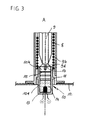
- the pyrotechnic trip unit with trigger member of Holding device consists of a per se known pyromechanical separator 10, which consists of two cylindrical parts 10 a and 10 b composed.
- the first part 10 a is formed as a hollow cylinder and together with the drive compression spring enveloping tube 9 b with a rotationally symmetric Fixing member 11 fixed to the vehicle at the bottom 12 of the cassette attached, wherein on the fastening member and the drive compression spring 8 is supported.
- the first part takes one over the so-called Squib 13 electrically ignitable pyrotechnic propellant 14 on.
- a locking ring 15 and a complementary groove 16 in the hollow cylindrical first part 10 a is also the second, as Solid cylinder formed part 10 b separable in the first hollow cylindrical part 10 a recorded.
- the locking ring 15th typically consists of an O-ring, which is in a corresponding circumferential groove of the second part 10 b is inserted. Training and arrangement of the locking ring 15 is made such that it by the prestressed drive compression spring 8 conditional holding forces in Range of 200 - 500 N safely absorbs.
- the holding member is in the illustrated embodiment by the Spring guide pin 9 is formed, the head side at point 9 c on Rollover body 1 hinged and foot side in the second part 10 b of the Separating element 10 is anchored, e.g. by a screw connection, with a threaded bolt portion 9 d on the spring guide pin and a sack threaded hole 17 in the head of the second partition member 10 b.
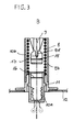
- the rollover protection system is stretched (Fig. 1 - 3 A).
- the drive compression spring can then the holding member 9 with the rollover body. 1 extend, as shown in the figure part 3 A.
- the invention also in a different than the illustrated rollover protection system can be used in particular with another holding member, another Rollover body and other guides of the rollover body.
- Essential is always that either the propellant containing the first Separator member 10 a fixed to the vehicle is mounted, and that ejectable second separating element part 10 b fixed to the holding member connected, or vice versa.
Landscapes
- Engineering & Computer Science (AREA)
- Mechanical Engineering (AREA)
- Physics & Mathematics (AREA)
- Fluid Mechanics (AREA)
- General Engineering & Computer Science (AREA)
- Chemical & Material Sciences (AREA)
- Analytical Chemistry (AREA)
- Automotive Seat Belt Assembly (AREA)
Abstract
Description
- Fig. 1
- in einer schematisierten Längsschnitt-Darstellung den Aufbau eines an sich bekannten Kassetten-Überrollschutzsystems mit aufstellbarem Überrollkörper und der erfindungsgemäßen Haltevorrichtung zum lösbaren Niederhalten des Überrollkörpers gegen die Vorspannkraft einer Antriebs-Druckfeder im Grundzustand,
- Fig. 2
- in einer isometrischen Darstellung das Überrollschutzsystem nach Fig. 1, ebenfalls im gespannten Grundzustand, und
- Fig. 3
- in zwei Figurenteilen A, B jeweils in einer Ausschnitt-Darstellung aus Fig. 1 den näheren Aufbau der erfindungsgemäßen Haltevorrichtung in zwei Betriebszuständen, mit dem gespannten Grundzustand im Figurenteil A und dem ausgelösten Zustand im Figurenteil B.
- 1
- Überrollkörper
- 2
- Führungsblock
- 3
- Seitliche Profilschienen
- 4
- Führungsglieder
- 5
- Überrollkopf
- 6
- Sperrglied
- 7
- Zahnsegment
- 8
- Antriebs-Druckfeder
- 9
- Federführungsbolzen + Halteglied
- 9 a
- Schulter
- 9 b
- Außenrohr
- 9 c
- Anlenkpunkt
- 9 d
- Gewindebolzen
- 10
- Trennelement
- 10 a
- erstes Trennelement-Teil
- 10 b
- zweites Trennelement-Teil
- 11
- Befestigungsglied
- 12
- Kassetten-Boden
- 13
- Zündpille
- 14
- pyrotechnischer Treibsatz
- 15
- Arretierungsring
- 16
- Nut
- 17
- Gewindesackloch
Claims (7)
- Überrollschutzsystem für Kraftfahrzeuge, mit einem verfahrbar in einer fahrzeugfesten Führung (2, 3) gehalterten Überrollkörper (1) , der im Normalzustand gegen die Kraft von mindestens einer vorgespannten Antriebs-Druckfeder (8) durch eine Haltevorrichtung in einer unteren, eingefahrenen Ruhelage haltbar ist, und unter Lösen der Haltevorrichtung durch die Federkraft der Antriebs-Druckfeder in eine verriegelte obere, schützende Stellung bringbar ist, wobei die Haltevorrichtung ein mit dem Überrollkörper verbundenes Halteglied und ein damit in lösbarer mechanischer Wirkverbindung stehendes Auslöseglied an einer fahrzeugfesten, sensorgesteuerten pyrotechnischen Auslöseeinheit aufweist, dadurch gekennzeichnet, daß das Auslöseglied mit der zugehörigen pyrotechnischen Auslöseeinheit durch ein pyromechanisches Trennelement (10) gebildet ist, das aus zwei Teilen besteht, von denen das erste Teil (10 a) einen elektrisch zündbaren pyrotechnischen Treibsatz (12, 13) enthält, und von denen das zweite Teil (10 b) über einen Arretierungsring (15) kraft- und formschlüssig trennbar mit dem ersten Teil (10 a) in Verbindung steht, wobei das eine Teil fahrzeugfest angebracht ist und das andere Teil fest mit dem Halteglied verbunden ist.
- Überrollschutzsystem nach Anspruch 1, dadurch gekennzeichnet, daß der Arretierungsring (15) aus einem O-Ring besteht.
- Überrollschutzsystem nach Anspruch 1 oder 2, dadurch gekennzeichnet, daß der Arretierungsring (15) so ausgelegt ist, daß er durch die vorgespannte Antriebs-Druckfeder (8) bedingte Haltekräfte im Bereich von 100 - 1500 N vorzugsweise von 200 - 700 N, sicher aufnimmt.
- Überrollschutzsystem nach einem der Ansprüche 1 bis 3, dadurch gekennzeichnet, daß das Halteglied durch einen Zugstab (9) gebildet ist, der mit einem Ende am Überrollkörper (1) und mit dem anderen Ende am Kopf des zweiten Teiles (10 b) des Trennelementes (10) verbunden ist.
- Überrollschutzsystem nach Anspruch 4, dadurch gekennzeichnet, daß der Zugstab (9) zugleich als Federführungsbolzen für die Antriebs-Druckfeder (8) ausgebildet ist.
- Überrollschutzsystem nach einem der Ansprüche 1 bis 5, mit einer kassettenartigen, fahrzeugfesten Führung, dadurch gekennzeichnet, daß der Überrollkörper (1) durch einen kassettenbreiten Profilkörper gebildet ist, der einmal in einem oberen Führungsblock (2) und zum anderen in länglichen, an den gegenüberliegenden Schmalseiten der Kassette angebrachten Profilschienen (3) geführt ist.
- Übenrollschutzsystem nach Anspruch 6, dadurch gekennzeichnet, daß an mindestens einer Schmalseite der Kassette und an der zugeordneten Schmalseite des Überrollkörpers (1) jeweils ein Sperrglied (6, 7) für eine Verriegelung des aufgestellten Überrollkörpers (1) vorgesehen ist.
Applications Claiming Priority (2)
| Application Number | Priority Date | Filing Date | Title |
|---|---|---|---|
| DE2003153867 DE10353867B3 (de) | 2003-11-18 | 2003-11-18 | Überrollschutzsystem für Kraftfahrzeuge mit einem ausfahrbaren Überrollkörper |
| DE10353867 | 2003-11-18 |
Publications (3)
| Publication Number | Publication Date |
|---|---|
| EP1547873A2 true EP1547873A2 (de) | 2005-06-29 |
| EP1547873A3 EP1547873A3 (de) | 2005-08-17 |
| EP1547873B1 EP1547873B1 (de) | 2009-01-14 |
Family
ID=33560387
Family Applications (1)
| Application Number | Title | Priority Date | Filing Date |
|---|---|---|---|
| EP20040022126 Expired - Lifetime EP1547873B1 (de) | 2003-11-18 | 2004-09-17 | Überrollschutzsystem für Kraftfahrzeuge mit einem ausfahrbaren Überrollkörper |
Country Status (2)
| Country | Link |
|---|---|
| EP (1) | EP1547873B1 (de) |
| DE (2) | DE10353867B3 (de) |
Families Citing this family (7)
| Publication number | Priority date | Publication date | Assignee | Title |
|---|---|---|---|---|
| DE102005028949C5 (de) * | 2005-06-22 | 2010-04-22 | Wilhelm Karmann Gmbh | Überrollschutzsystem für ein Kraftfahrzeug und Verfahren zur Herstellung eines Rastelementes des Überrollschutzsystems |
| DE102006016155B4 (de) * | 2006-04-06 | 2008-11-20 | Automotive Group Ise Innomotive Systems Europe Gmbh | Schutzvorrichtung in Kraftfahrzeugen zum Personenschutz |
| DE102006057030A1 (de) * | 2006-12-04 | 2008-06-26 | Automotive Group Ise Innomotive Systems Europe Gmbh | Überrollschutzsystem für Kraftfahrzeuge mit einem sensorgesteuert aktiv aufstellbaren Überrollkörper |
| DE102007013954A1 (de) * | 2007-03-23 | 2008-09-25 | Automotive Group Ise Innomotive Systems Europe Gmbh | Überrollschutzsystem für Kraftfahrzeuge mit einem sensorgesteuert aktiv aufstellbaren Überrollkörper |
| DE102013100824A1 (de) * | 2013-01-28 | 2014-07-31 | Benteler Automobiltechnik Gmbh | Kraftfahrzeug-Schutzvorrichtung |
| DE102013101210B4 (de) * | 2013-02-07 | 2017-09-21 | Benteler Automobiltechnik Gmbh | Fahrzeugschutzvorrichtung |
| DE102013106011A1 (de) * | 2013-06-10 | 2014-12-11 | Benteler Automobiltechnik Gmbh | Kraftfahrzeug-Schutzvorrichtung |
Family Cites Families (7)
| Publication number | Priority date | Publication date | Assignee | Title |
|---|---|---|---|---|
| DE4342400C2 (de) * | 1993-08-03 | 2002-06-13 | Ise Gmbh | Überrollbügeleinrichtung |
| DE19838989C1 (de) * | 1998-08-27 | 1999-11-11 | Ise Gmbh | Überroll-Schutzvorrichtung |
| DE19960764C5 (de) * | 1999-12-16 | 2012-11-22 | Autoliv Development Ab | Pyrotechnisch angetriebener Überrollbügel für Kraftfahrzeuge |
| DE10012573C1 (de) * | 2000-03-15 | 2001-03-01 | Ise Gmbh | Haltevorrichtung für den Überrollkörper eines Überrollschutzsystems |
| FR2810064B1 (fr) * | 2000-06-09 | 2005-08-05 | Giat Ind Sa | Verrou pyrotechnique comprenant un moyen de maintien axial de sa tige |
| DE10203710C1 (de) * | 2002-01-31 | 2003-02-13 | Thomas Magnete Gmbh | Pyrotechnischer Aktor |
| DE10303377A1 (de) * | 2003-01-29 | 2004-08-05 | Dynamit Nobel Ais Gmbh Automotive Ignition Systems | Pyromechanisches Trennelement |
-
2003
- 2003-11-18 DE DE2003153867 patent/DE10353867B3/de not_active Expired - Fee Related
-
2004
- 2004-09-17 EP EP20040022126 patent/EP1547873B1/de not_active Expired - Lifetime
- 2004-09-17 DE DE200450008861 patent/DE502004008861D1/de not_active Expired - Fee Related
Also Published As
| Publication number | Publication date |
|---|---|
| EP1547873B1 (de) | 2009-01-14 |
| EP1547873A3 (de) | 2005-08-17 |
| DE502004008861D1 (de) | 2009-03-05 |
| DE10353867B3 (de) | 2005-02-03 |
Similar Documents
| Publication | Publication Date | Title |
|---|---|---|
| DE102005059910B3 (de) | Überrollschutzsystem für Kraftfahrzeuge mit einem faltbaren Überrollbügel | |
| EP0916552B1 (de) | Ausfahrbarer Überrollbügel für Kraftfahrzeuge | |
| EP1736376A2 (de) | Bauteilgruppe für ein Cabriolet-Kraftfahrzeug | |
| DE10353867B3 (de) | Überrollschutzsystem für Kraftfahrzeuge mit einem ausfahrbaren Überrollkörper | |
| EP1736373B1 (de) | Überrollschutzsystem für ein Kraftfahrzeug | |
| DE102006028664B4 (de) | Überrollschutzsystem für ein Kraftfahrzeug | |
| DE10103247C1 (de) | Überrollschutzsystem für Kraftfahrzeuge | |
| DE10223420C2 (de) | Überrollschutzsystem für Kraftfahrzeuge mit Soll-Deformationsstelle | |
| EP2566726B1 (de) | Rahmenvorrichtung für ein überrollschutzsystem und überrollschutzsystem mit einer rahmenvorrichtung | |
| EP2420413B1 (de) | Überrollschutzsystem für Kraftfahrzeuge | |
| DE10103249C1 (de) | Überrollschutzsystem für Kraftfahrzeuge | |
| DE102005028966B4 (de) | Kraftfahrzeug mit einem Überrollschutzsystem an einer Fahrzeugquerwand | |
| EP1582420B1 (de) | Überrollschutzsystem für Kraftfahrzeuge mit einem ausfahrbaren Überrollkörper | |
| EP1514740B1 (de) | Überrollschutzsystem für Kraftfahrzeuge mit einem ausfahrbaren Überrollkörper | |
| DE10103245C1 (de) | Überrollschutzsystem für Kraftfahrzeuge | |
| EP1955907B1 (de) | Überrollschutzsystem mit Überrollbügel für Kraftfahrzeuge | |
| DE102013103204B4 (de) | Überrollschutzsystem für Kraftfahrzeuge | |
| DE102006002476B4 (de) | Überrollschutzsystem für ein Kraftfahrzeug | |
| DE102007013954A1 (de) | Überrollschutzsystem für Kraftfahrzeuge mit einem sensorgesteuert aktiv aufstellbaren Überrollkörper | |
| DE102006013913B4 (de) | Schutzvorrichtung in Kraftfahrzeugen zum Personenschutz | |
| DE102005028962A1 (de) | Überrollschutzsystem für ein Kraftfahrzeug | |
| DE102021120548A1 (de) | Überrollschutzvorrichtung für ein Kraftfahrzeug und Verfahren zur Herstellung einer Überrollschutzvorrichtung für ein Kraftfahrzeug | |
| EP1245460A2 (de) | Überrollschutzsystem für Kraftfahrzeuge mit einem pyrotechnischen Aktuator |
Legal Events
| Date | Code | Title | Description |
|---|---|---|---|
| PUAI | Public reference made under article 153(3) epc to a published international application that has entered the european phase |
Free format text: ORIGINAL CODE: 0009012 |
|
| AK | Designated contracting states |
Kind code of ref document: A2 Designated state(s): AT BE BG CH CY CZ DE DK EE ES FI FR GB GR HU IE IT LI LU MC NL PL PT RO SE SI SK TR |
|
| AX | Request for extension of the european patent |
Extension state: AL HR LT LV MK |
|
| PUAL | Search report despatched |
Free format text: ORIGINAL CODE: 0009013 |
|
| AK | Designated contracting states |
Kind code of ref document: A3 Designated state(s): AT BE BG CH CY CZ DE DK EE ES FI FR GB GR HU IE IT LI LU MC NL PL PT RO SE SI SK TR |
|
| AX | Request for extension of the european patent |
Extension state: AL HR LT LV MK |
|
| 17P | Request for examination filed |
Effective date: 20050903 |
|
| AKX | Designation fees paid |
Designated state(s): DE ES FR GB IT |
|
| 17Q | First examination report despatched |
Effective date: 20060320 |
|
| GRAP | Despatch of communication of intention to grant a patent |
Free format text: ORIGINAL CODE: EPIDOSNIGR1 |
|
| RAP1 | Party data changed (applicant data changed or rights of an application transferred) |
Owner name: ISE AUTOMOTIVE GMBH |
|
| GRAS | Grant fee paid |
Free format text: ORIGINAL CODE: EPIDOSNIGR3 |
|
| GRAA | (expected) grant |
Free format text: ORIGINAL CODE: 0009210 |
|
| AK | Designated contracting states |
Kind code of ref document: B1 Designated state(s): DE ES FR GB IT |
|
| REG | Reference to a national code |
Ref country code: GB Ref legal event code: FG4D Free format text: NOT ENGLISH |
|
| REF | Corresponds to: |
Ref document number: 502004008861 Country of ref document: DE Date of ref document: 20090305 Kind code of ref document: P |
|
| PG25 | Lapsed in a contracting state [announced via postgrant information from national office to epo] |
Ref country code: ES Free format text: LAPSE BECAUSE OF FAILURE TO SUBMIT A TRANSLATION OF THE DESCRIPTION OR TO PAY THE FEE WITHIN THE PRESCRIBED TIME-LIMIT Effective date: 20090425 |
|
| PLBE | No opposition filed within time limit |
Free format text: ORIGINAL CODE: 0009261 |
|
| STAA | Information on the status of an ep patent application or granted ep patent |
Free format text: STATUS: NO OPPOSITION FILED WITHIN TIME LIMIT |
|
| 26N | No opposition filed |
Effective date: 20091015 |
|
| GBPC | Gb: european patent ceased through non-payment of renewal fee |
Effective date: 20090917 |
|
| REG | Reference to a national code |
Ref country code: FR Ref legal event code: ST Effective date: 20100531 |
|
| PG25 | Lapsed in a contracting state [announced via postgrant information from national office to epo] |
Ref country code: FR Free format text: LAPSE BECAUSE OF NON-PAYMENT OF DUE FEES Effective date: 20090930 Ref country code: DE Free format text: LAPSE BECAUSE OF NON-PAYMENT OF DUE FEES Effective date: 20100401 |
|
| PG25 | Lapsed in a contracting state [announced via postgrant information from national office to epo] |
Ref country code: GB Free format text: LAPSE BECAUSE OF NON-PAYMENT OF DUE FEES Effective date: 20090917 |
|
| PG25 | Lapsed in a contracting state [announced via postgrant information from national office to epo] |
Ref country code: IT Free format text: LAPSE BECAUSE OF FAILURE TO SUBMIT A TRANSLATION OF THE DESCRIPTION OR TO PAY THE FEE WITHIN THE PRESCRIBED TIME-LIMIT Effective date: 20090114 |
|
| REG | Reference to a national code |
Ref country code: DE Ref legal event code: R081 Ref document number: 502004008861 Country of ref document: DE Owner name: METALSA AUTOMOTIVE GMBH, DE Free format text: FORMER OWNER: ISE AUTOMOTIVE GMBH, 51702 BERGNEUSTADT, DE Effective date: 20130812 |