EP0916552B1 - Ausfahrbarer Überrollbügel für Kraftfahrzeuge - Google Patents
Ausfahrbarer Überrollbügel für Kraftfahrzeuge Download PDFInfo
- Publication number
- EP0916552B1 EP0916552B1 EP98121339A EP98121339A EP0916552B1 EP 0916552 B1 EP0916552 B1 EP 0916552B1 EP 98121339 A EP98121339 A EP 98121339A EP 98121339 A EP98121339 A EP 98121339A EP 0916552 B1 EP0916552 B1 EP 0916552B1
- Authority
- EP
- European Patent Office
- Prior art keywords
- lever
- holding
- roll
- over
- actuator
- Prior art date
- Legal status (The legal status is an assumption and is not a legal conclusion. Google has not performed a legal analysis and makes no representation as to the accuracy of the status listed.)
- Expired - Lifetime
Links
Images

Classifications
-
- B—PERFORMING OPERATIONS; TRANSPORTING
- B60—VEHICLES IN GENERAL
- B60R—VEHICLES, VEHICLE FITTINGS, OR VEHICLE PARTS, NOT OTHERWISE PROVIDED FOR
- B60R21/00—Arrangements or fittings on vehicles for protecting or preventing injuries to occupants or pedestrians in case of accidents or other traffic risks
- B60R21/02—Occupant safety arrangements or fittings, e.g. crash pads
- B60R21/13—Roll-over protection
- B60R2021/132—Roll bars for convertible vehicles
- B60R2021/134—Roll bars for convertible vehicles movable from a retracted to a protection position
- B60R2021/135—Roll bars for convertible vehicles movable from a retracted to a protection position automatically during an accident
Definitions
- Such extendable rollover bodies in particular in the form of roll bars, such as are known, for example, from generic EP-A-0 729 867 can be found at Convertible vehicles use, where for optical reasons on one stare, i.e. permanently installed roll bar, is dispensed with.
- Fig. 3 shows in part A the known arrangement of a roll bar in Vehicle.
- the roll bar 1 is with a sheet metal cassette 2 Outer housing forms one, for example on the rear wall 3 of the vehicle Cabriolets, attached. It is located directly behind the backrest 4 a headrest 5 of the vehicle seats.
- the sheet metal cassette 2 closes approximately at the top flush with the backrest 4.
- a bracket cover 6 made of hard Plastic crossbar of the roll bar, over which the vehicle in Rollover rollover.
- This crossbar forms together with tubular Spars the roll bar, which with its spars in one in the upper part the sheet metal cassette 2 attached guide block in conjunction with at the bottom of the Cassette attached standpipes is guided in and out.
- the rollover body In the event of a rollover, the rollover body is triggered by a corresponding one Sensor, trigger and drive extended upwards. In the extended Position, the crossbar is clearly above the headrest and protects the heads of the buckled vehicle occupants in one Flashover.
- a triggering of the extension movement projects through the rear wall 3 pyrotechnic force element 7, which is thus in a simple manner after a Crash case can be replaced.
- Roll bars of the aforementioned type are in varied embodiments with regard to the structural design of the cassette, the roll body, the releasable holding device and the associated actuator, the Restart lock and the drive system extending the rollover body, known.
- the drives by means of a gas generator and a piston-cylinder system and by means of a show prestressed compression spring in connection with a pyrotechnic Primer or a crash magnet with a locking lever as a trigger system for the drive, i.e. as part of the releasable holding device.
- part B shows a greatly enlarged representation of a known direct acting release system with a cartridge 8 triggering a cartridge 9 with a pyrotechnic primer 9a in conjunction with a prestressed compression spring 10 for driving the rollover body, which via an element 11 of the Rollover body is locked with the pin 8 directly.
- the pyrotechnic primer 9a is ignited, a rapid gas expansion occurs within the cartridge 9, the force of which pushes the pin 8 to the left, as a result of which the roll bar is stopped and this is extended in a pulsed manner by means of the compression spring 10.
- 3 part C also shows a greatly enlarged illustration of an indirect triggering of the releasable holding device, with a so-called pin-ejecting pyrotechnic cartridge 9 'with an ignition element 9'a, which presses the pin 8 against a locking lever 12 in the event of triggering, which in the normal case is latched to a bolt-like member 13 connected to the roll bar and is unlatched in the event of a crash.
- the drive of the roll bar by means of a compression spring 10 is not shown in part C.
- the pyrotechnic cartridge by a so-called crash magnet be replaced, i.e. an electromagnet, which in the event of a crash Electricity from the vehicle electrical system is applied and the locking and Trigger pin 8 actuated.
- a crash magnet i.e. an electromagnet, which in the event of a crash Electricity from the vehicle electrical system is applied and the locking and Trigger pin 8 actuated.
- the invention is based, based on the task designated extendable roll bar this in terms of releasable To design the holding device so that in the event of a crash the actuator Unlocking the compression spring of the spring drive for the roll bar Forces to be applied with sufficient actuating force are smaller than with the comparable known constructions can be.
- a two-stage holding device in the form of a double lever system two levers in mechanical connection with each other are provided is, with a holding lever which is rotatable about an axis in a base body is attached, at one end a pawl extension for active engagement with the Has holding member on the rollover body, as well as the biased in the opening sense is, and with a trigger lever, which is also in the base body by one Axis is rotatably attached, at one end a jack extension for one Has active engagement with the free end of the holding lever, and that of Actuator for releasing the active engagement of the release lever with the holding lever is assigned, which is attached to the base body, the lever arms so are formed that on the operative connection between the holding member on Rolling body and the holding lever acting clamping friction on the mechanical linkage of both levers is reduced.
- a compact holding and Trigger device that requires only relatively small triggering forces created become.
- the double lever system enables the frictional force on the Active connection between the retaining bolt, which (indirectly) on the roll bar is attached, and the actuatable holding lever by the actuator due to the there is a not inconsiderable preload of the driving compression springs gear down so that the actuator can trip safely.
- DE 39 05 470 A1 is a two-stage holding and Locking device in the form of a double double lever system with each two levers in mechanical operative connection have become known.
- On three-armed lever has two projections for one Active intervention with recesses in the associated stirrup leg and the vehicle-fixed standpipe, in which the bracket leg is guided, whereas the other levers each establish the connection to the centrally located actuator.
- the construction is such that in the retracted state of the Roll bar one of the projections of the three-armed lever, the holding projection, with a recess in the standpipe, forming the holding function in Operational connection is made, and that in the event of tripping by pivoting the with Actuator-related lever the three-armed lever is released by swiveling the one hand by loosening the holding projection Roll bar releases and the other with the second projection, the Locking projection, through an operative connection with a recess in the Standpipe locks against retraction.
- a separate holding member typically an in a holding fork received holding bolt, on the holding fork on the Roll bar attached, provided, whereas in the case of the aforementioned DE document no separate holding member is provided, but in the standpipes of the Roll bar recesses are formed.
- this holding device is a completely different from that Re-entry lock separate component, i.e. represents a separate, independent component of the roll bar system, whereas the known Construction combines both functions, resulting in a complex, with large security risks associated construction leads, in contrast to The subject of the invention, which has proven itself in practice, in many cases used construction.
- the two levers of the single double lever system are in a base body rotatably attached, resulting in the compact design the triggerable holding device results in connection with that on the housing attached actuator.
- the levers are designed differently than in the case of the citation. You own hook-shaped extensions for active engagement with the separate retaining bolt or the free end of the holding lever. Such extensions are due to the different function of the lever systems in the known case not available.
- a first one Embodiment is that the bias of the holding lever by a lateral center offset of its axis of rotation relative to the holding member on Rollover body can be applied. In this embodiment, none additional parts needed.
- a second embodiment is that a biased torsion spring is provided, which is attached to the base body and with the holding lever is in active engagement in the unlatching sense.
- the actuator of the release system can also be implemented in various ways become.
- the actuator can a pyrotechnic propellant ignited in a cartridge or have actuated by a trigger electromagnet pin which on the Release lever in the event of a crash acts in the unlocked sense.
- a pin-free one is also available Tripping possible if the actuator has a tripping electromagnet Has connection with a magnetized portion in the trigger lever.
- the electromagnet can then be switched on without a pin on the release lever act unlocked senses.
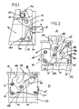
- FIG. 1 shows a holding device in a schematic representation a release system for an extendable roll bar, consisting of a pin-operated double lever holding and triggering system.
- This double lever hold and release system has a holding lever 14 which by means of a hook-shaped pawl extension 14a with a retaining bolt 15, the retaining member, is latched to the rollover body as shown in FIG. 3C.
- On the pawl extension 14 a therefore exercises the retaining pin 15 through the preloaded compression spring of the drive applied force.
- This holding lever 14 is rotatable about the axis 17 via a bracket-like bracket 18 on a Base body 16 in a rollover body and its spring drive receiving sheet metal cassette analogous to Fig. 3 A attached.
- the center of the axis 17 is laterally by the distance "a" from the center of the retaining bolt 15 added. This is due to the spring force of the compression spring drive Holding lever 14 exerted a moment acting in the unlatching sense.
- the double lever system also has a release lever 19 which is around the Axis 20 is rotatably attached to the base body 16, and with a hook-shaped pawl extension 19a with the holding lever 14 at its free end 14b is latched.
- the trigger system also has a symbolically represented actuator 9 a trigger pin 8, which is in operative connection with the free end of the Release lever 19 is.
- the trigger pin 8 can with a cartridge Propellant charge analogous to FIG. 3 C or by means of an electric crash magnet in the Crash case are operated.
- the release system is designed so that the release time is not enlarged and that it does not automatically move into the Starting position jumps back, i.e. reversing is done by an external one Force on the locking lever 14 against the force of the compression spring Spring drive of the roll bar.
- State A is the idle state that State B is the triggered state.
- the trigger lever 19 'rotatably mounted on the base body 16' about the axis 20 ' is bow-shaped and stands with its flat, flanged handle extension 19'a with a pawl stop 14'b of the holding lever 14 'in interlocking operative connection.
- This operative connection is made by a torsion spring 21, which is attached at one end to the base body 16 'and the free end 21a on the free end of the magnetizing section 19'b Release lever 19 'rests and presses it down, made.
- a trigger electromagnet 22 which Crash magnet as an actuator that magnetizes the magnet when it is switched on Section at the end 19'b of the release lever 19 'presses up and thus how shown in Fig. 2 B, the latch with the holding lever 14 'releases.
- this is released with the release of the latching with the retaining bolt 15 on the rollover body by means of the compression spring of the rollover drive exerted moment, supported by the prestressed help torsion spring 24 to the axis 17 'in the position shown in Fig. 2 B rotated against a stop 23.
- FIG. 2 The embodiment shown in FIG. 2 is also supported by the potential energy of the preloaded torsion spring 24 and the lever ratios, the clamping friction force on the catch 14'b and 19'a of the release lever 19 ' with the holding lever 14 'smaller than at the latching of the holding lever 14' the bolt 15.
- a Trigger pin can be provided which on the underside of the trigger lever 19 ' acts and drives it up in the event of a crash.
Landscapes
- Engineering & Computer Science (AREA)
- Mechanical Engineering (AREA)
- Automotive Seat Belt Assembly (AREA)
- Air Bags (AREA)
- Holders For Apparel And Elements Relating To Apparel (AREA)
Description
- einer lösbaren Haltevorrichtung zum Halten des Überrollkörpers bei vorgespannter Druckfeder in der abgesenkten Ruhelage, die in direkter Wirkverbindung mit einem am Überrollbügel befestigten Halteglied steht,
- einem Aktuator für das Lösen der Haltevorrichtung im Crash-Fall, sowie
- einer von der Haltevorrichtung unabhängigen Verriegelungseinrichtung als Wiedereinfahrsperre bei ausgefahrenem Überrollbügel.
Die Fig. 3 Teil C zeigt ebenfalls in einer stark vergrößerten Darstellung eine indirekte Auslösung der lösbaren Haltevorrichtung, mit einer sogenannten stiftausstoßenden pyrotechnischen Patrone 9' mit einem Zündsatz 9'a, die den Stift 8 im Auslösefall gegen einen Verriegelungshebel 12 drückt, der im Normalfall mit einem mit dem Überrollbügel verbundenen bolzenartigen Glied 13 verklinkt ist und der im Crash-Fall entklinkt wird. Der vereinfachten Darstellung wegen ist dabei im Teil C der Antrieb des Überrollbügels mittels einer Druckfeder 10 nicht dargestellt.
- einer lösbaren Haltevorrichtung zum Halten des Überrollkörpers bei vorgespannter Druckfeder in der abgesenkten Ruhelage, die in direkter Wirkverbindung mit einem am Überrollbügel befestigten Halteglied steht,
- einem Aktuator für das Lösen der Haltevorrichtung im Crash-Fall, sowie
- einer von der Haltevorrichtung unabhängigen Verriegelungseinrichtung als Wiedereinfahrsperre bei ausgefahrenem Überrollbügel,
- Fig. 1
- in einer schematisierten Schnittdarstellung eine erste Ausführungsform eines Doppelhebel-Halte- und Auslösesystems mit Auslösung durch einen Stift,
- Fig. 2
- in einer weiteren schematisierten Schnittdarstellung ein zweites Ausführungsbeispiel eines Doppelhebel-Halte- und Auslösesystems mit einer stiftfreien Auslösung über einen Crash-Magneten, wobei im Teil A der verriegelte Zustand und im Teil B der entriegelte, d.h. ausgelöste Zustand, dargestellt ist, und
- Fig. 3
- im Teil A die bekannte Anordnung eines ausfahrbaren Überrollbügels hinter den Fahrzeugsitzen und in den Teilen B und C zwei verschiedene Ausführungsformen von bekannten Halte- und Auslösesystemen.
Claims (5)
- Überrollschutzsystem für Kraftfahrzeuge, bestehend aus einem Überrollkörper (1) sowie einer Blechkassette (2) mit einem Führungskörper für den Überrollkörper und einer mit ihm in antreibender Wirkverbindung stehenden Druckfeder (10) zum Ausfahren des Überrollkörpers aus einer abgesenkten Ruhelage in eine obere Stützlage im Crash-Fall, mitdadurch gekennzeichnet, daß eine zweistufige Haltevorrichtung in Form eines Doppelhebelsystems (14,19) mit zwei in mechanischer Wirkverbindung miteinander stehenden Hebeln, einem Halte- (14) und einem Auslösehebel (19), vorgesehen ist,einer lösbaren Haltevorrichtung (14, 19, 15; 14', 24, 19', 15) zum Halten des Überrollkörpers (1) bei vorgespannter Druckfeder (10) in der abgesenkten Ruhelage, die in direkter Wirkverbindung mit einem am Überrollbügel (1) befestigten Halteglied (15) steht,einem Aktuator (8, 9; 22) für das Lösen der Haltevorrichtung im Crash-Fall, sowieeiner von der Haltevorrichtung unabhängigen Verriegelungseinrichtung als Wiedereinfahrsperre bei ausgefahrenem Überrollbügel,
von denen der Haltehebel (14, 14'), der in einem Grundkörper (16, 16') um eine Achse (17, 17') drehbar angebracht ist, an einem Ende einen Klinkenfortsatz (14a, 14'a) für den Wirkeingriff mit dem Halteglied (15) am Überrollkörper (1) besitzt, sowie der im öffnenden Sinne vorgespannt ist, und von denen der Auslösehebel (19, 19'), der ebenfalls in dem Grundkörper (16, 16') um eine Achse (20, 20') drehbar angebracht ist, an einem Ende einen Klinkenfortsatz (19a, 19'a) für einen Wirkeingriff mit dem freien Ende (14b, 14'b) des Haltehebels (14, 14') besitzt, sowie dem der Aktuator (8, 9; 22) zum Lösen des Wirkeingriffes des Auslösehebels (19, 19') mit dem Haltehebel (14, 14') zugeordnet ist, wobei die Hebelarme in ihrer Länge so ausgebildet sind, daß die an der Wirkverbindung zwischen dem Halteglied (15) am Überrollkörper und dem Haltehebel (14, 14') wirkende Klemm-Reibkraft an der mechanischen Wirkverbindung beider Hebel untersetzt ist. - Überrollbügel nach Anspruch 1, dadurch gekennzeichnet, daß die Vorspannung des Haltehebels (14) durch einen seitlichen Mittenversatz seiner Drehachse (17) gegenüber dem Halteglied (15) am Überrollkörper aufbringbar ist.
- Überrollschutzsystem nach Anspruch 1 oder 2, dadurch gekennzeichnet, daß eine vorgespannte Drehfeder (24) vorgesehen ist, die am Grundkörper (16') befestigt ist und mit dem Haltehebel (14') im entklinkenden Sinne in Wirkeingriff steht.
- Überrollschutzsystem nach einem der Ansprüche 1 bis 3, dadurch gekennzeichnet, daß der Aktuator (9) einen durch einen in einer Patrone gezündeten pyrotechnischen Treibsatz oder durch einen Auslöse-Elektromagneten betätigten Stift (8) aufweist, der auf den Auslösehebel (19) im Crash-Fall im entriegelten Sinne einwirkt.
- Überrollschutzsystem nach einem der Ansprüche 1 bis 3, dadurch gekennzeichnet, daß der Aktuator (9) einen Auslöse-Elektromagneten (22) in Verbindung mit einem magnetisierten Abschnitt (19'b) im Auslösehebel (19') aufweist.
Applications Claiming Priority (2)
| Application Number | Priority Date | Filing Date | Title |
|---|---|---|---|
| DE19750693A DE19750693C2 (de) | 1997-11-15 | 1997-11-15 | Ausfahrbarer Überrollbügel für Kraftfahrzeuge |
| DE19750693 | 1997-11-15 |
Publications (2)
| Publication Number | Publication Date |
|---|---|
| EP0916552A1 EP0916552A1 (de) | 1999-05-19 |
| EP0916552B1 true EP0916552B1 (de) | 2002-09-04 |
Family
ID=7848857
Family Applications (1)
| Application Number | Title | Priority Date | Filing Date |
|---|---|---|---|
| EP98121339A Expired - Lifetime EP0916552B1 (de) | 1997-11-15 | 1998-11-10 | Ausfahrbarer Überrollbügel für Kraftfahrzeuge |
Country Status (3)
| Country | Link |
|---|---|
| EP (1) | EP0916552B1 (de) |
| DE (2) | DE19750693C2 (de) |
| ES (1) | ES2181110T3 (de) |
Families Citing this family (14)
| Publication number | Priority date | Publication date | Assignee | Title |
|---|---|---|---|---|
| DE19937150B4 (de) * | 1999-08-06 | 2005-03-31 | Daimlerchrysler Ag | Überrollschutz-Vorrichtung für ein Kraftfahrzeug |
| DE19949944C1 (de) * | 1999-10-16 | 2000-12-28 | Ise Gmbh | Haltevorrichtung für den Überrollkörper eines Überollschutzsystems |
| DE10038431A1 (de) * | 2000-08-07 | 2002-02-21 | Volkswagen Ag | Kraftverschluß für eine Fahrzeugsicherheitseinrichtung |
| DE10044926C1 (de) * | 2000-09-12 | 2001-09-06 | Ise Gmbh | Überrollschutzsystem |
| DE10229635C1 (de) | 2002-07-02 | 2003-07-10 | Ise Gmbh | Überrollschutzsystem für Kraftfahrzeuge |
| ES2276998T3 (es) * | 2003-06-16 | 2007-07-01 | Thomas Magnete Gmbh | Dispositivo para accionar una pieza constructiva que se mueve con rapiudez. |
| DE10358774A1 (de) * | 2003-12-12 | 2005-07-14 | Brose Schließsysteme GmbH & Co.KG | Haltevorrichtung für eine Fahrzeugsicherheitseinrichtung |
| DE102004015808B3 (de) * | 2004-03-31 | 2005-03-10 | Ise Gmbh | Überrollschutzsystem für Kraftfahrzeuge mit einem ausfahrbaren Überrollkörper |
| EP1899198B1 (de) * | 2005-06-21 | 2011-10-19 | Kongsberg Devotek AS | Mechanismus zur lösbaren halterung und verwendungsverfahren |
| CN101253070B (zh) * | 2005-06-21 | 2011-09-07 | 孔斯贝格德沃泰克股份公司 | 可释放的保持机构及其使用方法 |
| DE102005028960B4 (de) | 2005-06-22 | 2007-10-25 | Wilhelm Karmann Gmbh | Lösbare Halteeinrichtung zum Halten eines Überrollkörpers einer Überrollschutzvorrichtung eines Kraftfahrzeuges |
| DE102005028928B4 (de) * | 2005-06-22 | 2007-04-12 | Wilhelm Karmann Gmbh | Lösbare Halteeinrichtung zum Halten eines Überrollkörpers einer Überrollschutzvorrichtung eines Kraftfahrzeuges |
| DE102005028923B4 (de) * | 2005-06-22 | 2007-11-08 | Wilhelm Karmann Gmbh | Überrollschutzsystem für ein Kraftfahrzeug, insbesondere für ein Cabriolet |
| EP2246222B1 (de) * | 2010-01-08 | 2012-09-19 | ISE Automotive GmbH | Überrollschutzsytem für Kraftfahrzeuge |
Family Cites Families (7)
| Publication number | Priority date | Publication date | Assignee | Title |
|---|---|---|---|---|
| DE3905470A1 (de) * | 1989-02-22 | 1990-12-06 | Autoliv Kolb Gmbh & Co | Ausfahrbarer ueberrollbuegel fuer cabriolets |
| DE3930171C2 (de) * | 1989-09-09 | 1996-02-01 | Keiper Recaro Gmbh Co | Überrollschutz |
| EP0729867B1 (de) * | 1993-05-03 | 1999-06-02 | Bayerische Motoren Werke Aktiengesellschaft, Patentabteilung AJ-3 | Überrollschutz-Vorrichtung für ein Kraftfahrzeug |
| DE4345523C2 (de) * | 1993-08-03 | 2002-05-23 | Ise Gmbh | Überrollschutzsystem |
| DE4342401B4 (de) * | 1993-12-13 | 2004-09-30 | Ise Innomotive Systems Europe Gmbh | Überrollbügel für Kraftfahrzeuge |
| DE19523790C2 (de) * | 1995-07-04 | 2000-07-20 | Ise Gmbh | Ausfahrbarer Überrollbügel |
| DE19531599A1 (de) * | 1995-08-28 | 1997-03-06 | Bayerische Motoren Werke Ag | Kupplung für ein in eine Wirkstellung verlagerbares Sicherheitsteil eines Fahrzeugs, insbesondere für einen Überrollbügel |
-
1997
- 1997-11-15 DE DE19750693A patent/DE19750693C2/de not_active Expired - Fee Related
-
1998
- 1998-11-10 EP EP98121339A patent/EP0916552B1/de not_active Expired - Lifetime
- 1998-11-10 ES ES98121339T patent/ES2181110T3/es not_active Expired - Lifetime
- 1998-11-10 DE DE59805392T patent/DE59805392D1/de not_active Expired - Lifetime
Also Published As
| Publication number | Publication date |
|---|---|
| EP0916552A1 (de) | 1999-05-19 |
| DE59805392D1 (de) | 2002-10-10 |
| DE19750693C2 (de) | 2002-03-21 |
| DE19750693A1 (de) | 1999-05-27 |
| ES2181110T3 (es) | 2003-02-16 |
Similar Documents
| Publication | Publication Date | Title |
|---|---|---|
| DE4345524C2 (de) | Überrollschutzsystem | |
| EP1359059B1 (de) | Überrollschutzsystem für Kraftfahrzeuge mit einer selbsthaltenden Entriegelungseinrichtung | |
| EP0916552B1 (de) | Ausfahrbarer Überrollbügel für Kraftfahrzeuge | |
| EP1186481B1 (de) | Überrollschutzsystem für Kraftfahrzeuge | |
| EP0709248B1 (de) | Kraftfahrzeugsitz mit einer nach vorn schwenkbaren Rückenlehne | |
| EP1736376A2 (de) | Bauteilgruppe für ein Cabriolet-Kraftfahrzeug | |
| EP1186483B1 (de) | Fahrzeugfestes Überrollschutzsystem-Gehäuse mit aus- und einfahrbargeführtem Überrollkörper | |
| EP1736373B1 (de) | Überrollschutzsystem für ein Kraftfahrzeug | |
| EP1095823B1 (de) | Überrollschutzsystem für Kraftfahrzeuge | |
| EP1857332A2 (de) | Überrollschutzsystem für Kraftfahrzeuge mit mindestens einem aktiv aufstellbaren Überrollkörper | |
| DE102006028664B4 (de) | Überrollschutzsystem für ein Kraftfahrzeug | |
| EP1525121B1 (de) | Überrollschutzsystem für kraftfahrzeuge | |
| DE10103247C1 (de) | Überrollschutzsystem für Kraftfahrzeuge | |
| EP1547873B1 (de) | Überrollschutzsystem für Kraftfahrzeuge mit einem ausfahrbaren Überrollkörper | |
| EP1955908A1 (de) | Überrollschutzsystem für Kraftfahrzeuge mit einem sensorgesteuert aktiv aufstellbaren Überrollkörper | |
| DE19910424C1 (de) | Überroll-Schutzvorrichtung für Kraftfahrzeuge | |
| DE10103249C1 (de) | Überrollschutzsystem für Kraftfahrzeuge | |
| EP1582420B1 (de) | Überrollschutzsystem für Kraftfahrzeuge mit einem ausfahrbaren Überrollkörper | |
| DE10103245C1 (de) | Überrollschutzsystem für Kraftfahrzeuge | |
| DE102008002138B4 (de) | Überrollschutzsystem für Personenkraftwagen | |
| EP1514740B1 (de) | Überrollschutzsystem für Kraftfahrzeuge mit einem ausfahrbaren Überrollkörper | |
| DE19860165C1 (de) | Überroll-Schutzvorrichtung für Kraftfahrzeuge | |
| EP1493635A1 (de) | Überrollbügel-System für ein Cabriolet | |
| EP1245460B1 (de) | Überrollschutzsystem für Kraftfahrzeuge mit einem pyrotechnischen Aktuator |
Legal Events
| Date | Code | Title | Description |
|---|---|---|---|
| PUAI | Public reference made under article 153(3) epc to a published international application that has entered the european phase |
Free format text: ORIGINAL CODE: 0009012 |
|
| AK | Designated contracting states |
Kind code of ref document: A1 Designated state(s): DE ES FR GB IT |
|
| AX | Request for extension of the european patent |
Free format text: AL;LT;LV;MK;RO;SI |
|
| 17P | Request for examination filed |
Effective date: 19990626 |
|
| AKX | Designation fees paid |
Free format text: DE ES FR GB IT |
|
| 17Q | First examination report despatched |
Effective date: 20010402 |
|
| GRAG | Despatch of communication of intention to grant |
Free format text: ORIGINAL CODE: EPIDOS AGRA |
|
| GRAG | Despatch of communication of intention to grant |
Free format text: ORIGINAL CODE: EPIDOS AGRA |
|
| GRAH | Despatch of communication of intention to grant a patent |
Free format text: ORIGINAL CODE: EPIDOS IGRA |
|
| GRAH | Despatch of communication of intention to grant a patent |
Free format text: ORIGINAL CODE: EPIDOS IGRA |
|
| GRAA | (expected) grant |
Free format text: ORIGINAL CODE: 0009210 |
|
| AK | Designated contracting states |
Kind code of ref document: B1 Designated state(s): DE ES FR GB IT |
|
| REG | Reference to a national code |
Ref country code: GB Ref legal event code: FG4D Free format text: NOT ENGLISH |
|
| REF | Corresponds to: |
Ref document number: 59805392 Country of ref document: DE Date of ref document: 20021010 |
|
| GBT | Gb: translation of ep patent filed (gb section 77(6)(a)/1977) |
Effective date: 20021218 |
|
| REG | Reference to a national code |
Ref country code: ES Ref legal event code: FG2A Ref document number: 2181110 Country of ref document: ES Kind code of ref document: T3 |
|
| ET | Fr: translation filed | ||
| PLBE | No opposition filed within time limit |
Free format text: ORIGINAL CODE: 0009261 |
|
| STAA | Information on the status of an ep patent application or granted ep patent |
Free format text: STATUS: NO OPPOSITION FILED WITHIN TIME LIMIT |
|
| 26N | No opposition filed |
Effective date: 20030605 |
|
| PGFP | Annual fee paid to national office [announced via postgrant information from national office to epo] |
Ref country code: ES Payment date: 20081121 Year of fee payment: 11 |
|
| PGFP | Annual fee paid to national office [announced via postgrant information from national office to epo] |
Ref country code: IT Payment date: 20081126 Year of fee payment: 11 |
|
| PGFP | Annual fee paid to national office [announced via postgrant information from national office to epo] |
Ref country code: FR Payment date: 20081118 Year of fee payment: 11 |
|
| PGFP | Annual fee paid to national office [announced via postgrant information from national office to epo] |
Ref country code: GB Payment date: 20081121 Year of fee payment: 11 |
|
| GBPC | Gb: european patent ceased through non-payment of renewal fee |
Effective date: 20091110 |
|
| REG | Reference to a national code |
Ref country code: FR Ref legal event code: ST Effective date: 20100730 |
|
| PG25 | Lapsed in a contracting state [announced via postgrant information from national office to epo] |
Ref country code: FR Free format text: LAPSE BECAUSE OF NON-PAYMENT OF DUE FEES Effective date: 20091130 |
|
| PG25 | Lapsed in a contracting state [announced via postgrant information from national office to epo] |
Ref country code: GB Free format text: LAPSE BECAUSE OF NON-PAYMENT OF DUE FEES Effective date: 20091110 |
|
| PG25 | Lapsed in a contracting state [announced via postgrant information from national office to epo] |
Ref country code: IT Free format text: LAPSE BECAUSE OF NON-PAYMENT OF DUE FEES Effective date: 20091110 |
|
| REG | Reference to a national code |
Ref country code: ES Ref legal event code: FD2A Effective date: 20110404 |
|
| PG25 | Lapsed in a contracting state [announced via postgrant information from national office to epo] |
Ref country code: ES Free format text: LAPSE BECAUSE OF NON-PAYMENT OF DUE FEES Effective date: 20110322 |
|
| PG25 | Lapsed in a contracting state [announced via postgrant information from national office to epo] |
Ref country code: ES Free format text: LAPSE BECAUSE OF NON-PAYMENT OF DUE FEES Effective date: 20091111 |
|
| REG | Reference to a national code |
Ref country code: DE Ref legal event code: R082 Ref document number: 59805392 Country of ref document: DE Representative=s name: KALKOFF & PARTNER PATENTANWAELTE, DE |
|
| REG | Reference to a national code |
Ref country code: DE Ref legal event code: R082 Ref document number: 59805392 Country of ref document: DE Representative=s name: REBBEREH, CORNELIA, DIPL.-ING., DE Effective date: 20130812 Ref country code: DE Ref legal event code: R082 Ref document number: 59805392 Country of ref document: DE Representative=s name: KALKOFF & PARTNER PATENTANWAELTE, DE Effective date: 20130812 Ref country code: DE Ref legal event code: R081 Ref document number: 59805392 Country of ref document: DE Owner name: METALSA AUTOMOTIVE GMBH, DE Free format text: FORMER OWNER: ISE AUTOMOTIVE GMBH, 51702 BERGNEUSTADT, DE Effective date: 20130812 |
|
| REG | Reference to a national code |
Ref country code: DE Ref legal event code: R082 Ref document number: 59805392 Country of ref document: DE Representative=s name: REBBEREH, CORNELIA, DIPL.-ING., DE |
|
| PGFP | Annual fee paid to national office [announced via postgrant information from national office to epo] |
Ref country code: DE Payment date: 20151103 Year of fee payment: 18 |
|
| REG | Reference to a national code |
Ref country code: DE Ref legal event code: R119 Ref document number: 59805392 Country of ref document: DE |
|
| PG25 | Lapsed in a contracting state [announced via postgrant information from national office to epo] |
Ref country code: DE Free format text: LAPSE BECAUSE OF NON-PAYMENT OF DUE FEES Effective date: 20170601 |