EP1547861A2 - Fahrzeugleuchte - Google Patents
Fahrzeugleuchte Download PDFInfo
- Publication number
- EP1547861A2 EP1547861A2 EP04030709A EP04030709A EP1547861A2 EP 1547861 A2 EP1547861 A2 EP 1547861A2 EP 04030709 A EP04030709 A EP 04030709A EP 04030709 A EP04030709 A EP 04030709A EP 1547861 A2 EP1547861 A2 EP 1547861A2
- Authority
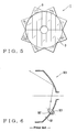
- EP
- European Patent Office
- Prior art keywords
- reflector
- light
- close
- headlight
- vehicular lamp
- Prior art date
- Legal status (The legal status is an assumption and is not a legal conclusion. Google has not performed a legal analysis and makes no representation as to the accuracy of the status listed.)
- Granted
Links
Images


Classifications
-
- B—PERFORMING OPERATIONS; TRANSPORTING
- B60—VEHICLES IN GENERAL
- B60Q—ARRANGEMENT OF SIGNALLING OR LIGHTING DEVICES, THE MOUNTING OR SUPPORTING THEREOF OR CIRCUITS THEREFOR, FOR VEHICLES IN GENERAL
- B60Q1/00—Arrangement of optical signalling or lighting devices, the mounting or supporting thereof or circuits therefor
- B60Q1/0029—Spatial arrangement
- B60Q1/0041—Spatial arrangement of several lamps in relation to each other
- B60Q1/0052—Spatial arrangement of several lamps in relation to each other concentric
-
- F—MECHANICAL ENGINEERING; LIGHTING; HEATING; WEAPONS; BLASTING
- F21—LIGHTING
- F21S—NON-PORTABLE LIGHTING DEVICES; SYSTEMS THEREOF; VEHICLE LIGHTING DEVICES SPECIALLY ADAPTED FOR VEHICLE EXTERIORS
- F21S41/00—Illuminating devices specially adapted for vehicle exteriors, e.g. headlamps
- F21S41/30—Illuminating devices specially adapted for vehicle exteriors, e.g. headlamps characterised by reflectors
- F21S41/32—Optical layout thereof
- F21S41/33—Multi-surface reflectors, e.g. reflectors with facets or reflectors with portions of different curvature
- F21S41/337—Multi-surface reflectors, e.g. reflectors with facets or reflectors with portions of different curvature the reflector having a structured surface, e.g. with facets or corrugations
-
- F—MECHANICAL ENGINEERING; LIGHTING; HEATING; WEAPONS; BLASTING
- F21—LIGHTING
- F21W—INDEXING SCHEME ASSOCIATED WITH SUBCLASSES F21K, F21L, F21S and F21V, RELATING TO USES OR APPLICATIONS OF LIGHTING DEVICES OR SYSTEMS
- F21W2103/00—Exterior vehicle lighting devices for signalling purposes
- F21W2103/10—Position lights
Definitions
- the present invention relates to a vehicular lamp. More particularly, it relates to a vehicular lamp configured to combine two lights having respective purposes, such as a headlight for illuminating a traveling path of a particular vehicle at night and a position lamp for indicating the existence of the particular vehicle to oncoming vehicles at night, for example.
- a vehicular lamp such as a headlamp 90, equipped with a position bulb 93 as shown in Fig. 6 has been well known in the art.
- the headlamp 90 includes a reflector 91 with a hole 92 formed therethrough.
- the position bulb 93 protrudes through the hole 92 into the lamp.
- the position bulb 93 is turned on if necessary, for example, at dusk to indicate the existence of a particular vehicle to other vehicles at night when the headlamp 90 is not turned on.
- the position bulb 93 can make the entire surface of the reflector 91 of the headlight 90 brilliant to improve the visibility from oncoming vehicles.
- light from the position bulb reflects at the reflector 91 of the headlight 90 efficiently to cause an intensive upward reflected light as shown in Fig. 6, it acts undesirably, for example, dazzles oncoming vehicles (see JP-A 11-260106).
- the present invention provides a vehicular lamp as a specific means for solving the above problems in the art.
- a vehicular lamp comprising a main light source; a concave main reflector having a front end and an outer circumference for reflecting light from said main light source in a first direction; a secondary light source provided in the concave main reflector on a portion located at or close to the front end and also located at or close to the outer circumference; and a generally annular secondary reflector at or close to the front end of the concave main reflector for reflecting light from the secondary light source in said first direction.
- the vehicular lamp further comprises a lens provided in the path of light reflected from the secondary reflector for distribution control of the light reflected from the secondary reflector.
- the lens is attached to said concave main reflector at or close to the front end thereof in an integral or multi-part split state.
- the concave main reflector is a headlight reflector;
- the secondary light source is a sidelight source provided in the headlight reflector on a portion located at or close to the front end and also located at or close to the outer circumference;
- the secondary reflector is a position reflector provided almost in the form of a ring in an integral or split state at or close to the front end of the headlight reflector to reflect light from the sidelight source toward the front in a certain direction.
- the lens is preferably a position lens provided on a location in a direction of light reflected from the position reflector for distribution control of the light reflected from the position reflector.
- the position lens is preferably attached to a location at or close to the front end of the headlight reflector in an integral or multi-part split state.
- the vehicular lamp comprises a headlight reflector having a front end and an outer circumference.
- a sidelight source is provided in the headlight reflector on a portion located at or close to the front end and also located at or close to the outer circumference.
- a position reflector is provided almost in the form of a ring in an integral or split state at or close to the front end of the headlight reflector to reflect light from the sidelight source toward the front in a certain direction.
- the vehicular lamp may further comprise a position lens provided on a location in a direction of light reflected from the position reflector for distribution control of the light reflected from the position reflector. In the vehicular lamp, the position lens may be attached to a location at or close to the front end of the headlight reflector in an integral or multi-part split state.
- the sidelight source is provided in the headlight reflector on a portion located at or close to the front end and also located at or close to the outer circumference.
- the position reflector is provided to receive light from the sidelight source and reflect the light as one almost in the form of a ring toward a location in a certain direction.
- the vehicular lamp 1 is formed as a headlight for use in formation of a high beam distribution.
- the vehicular lamp 1 comprises a light source 2 such as a halogen bulb and a discharge lamp, and a headlight reflector 3 operative to reflect light from the light source 2 to form the high beam distribution.
- the reference numeral 20 is employed in the figures to denote a headlight for use in formation of a low beam distribution.
- the headlight 20 is formed in the so-called projector type and configured to project no upward light at all except for a certain direction such as toward the left roadside in the left side passage. This configuration is not related to the gist of the present invention and its detailed description is omitted.
- an attachment hole 3a is provided through the headlight reflector 3 close to an outer circumference thereof for attachment of a sidelight source 4 thereto.
- a position reflector 5 is provided almost in the form of a ring to receive light from the sidelight source 4 and reflect it toward a location in a certain direction.
- the reference numeral 7 is employed in Fig. 2 to denote an outer lens.
- the vehicular lamp 1 is preferred in terms of designing if it is excellent in transparency.
- lens-cut is applied to the outer lens to form the light distribution of the headlight.
- the light distribution is formed at the headlight reflector 3 while remaining the outer lens 7 almost plain. Therefore, the light reflected from the position reflector 5 is not diffused and can be recognized from external after it transmits through the outer lens 7 while remaining the shape such as the ring.
- the above configuration may allow, when the sidelight source 4 is turned on, the light from the sidelight source 4 to reach only the position reflector 5 or both the headlight reflector 3 and the position reflector 5.
- the position light sidelight
- the following description is given on the assumption that it allows the light to reach only the position reflector 5.
- the position reflector 5 which reflects it forward from the vehicle to allow viewers to see a brilliant ring of light.
- the above situation occurs, for example, at dusk when the headlight source 2 has not been yet turned on. Therefore, the portion of the position reflector 5 located at the rim of the headlight reflector 3 can be seen as the brilliant ring from oncoming vehicles (see also Fig. 1).
- the sidelight source 4 may be provided with a colored bulb or a cover having a corresponding color to achieve a desired color of light.
- the light from the brighter headlight source 2 becomes dominant and whitens the light reflected from the position reflector 5.
- the position reflector 5 is located in the headlight reflector 3 on a location at or close to the front end thereof and more forward than the headlight source 2 as shown in Fig. 2. Thus, even when the headlight source 2 is turned on, the light therefrom is prevented from entering the position reflector 5.
- the entire or partial surface of the headlight reflector 3 surely shines in a color of light yellow, or orange.
- the light can be whitened without any practical trouble when the headlight source 2 is turned on. Therefore, it is simply freedom of choice in terms of designing to select the light from the sidelight source 4 that impinges on the headlight reflector 3 or not.
- the position reflector 5 provided close to the outer circumference of the headlight reflector 3 shines in a color of orange or light yellow whenever the sidelight source 4 is turned on, regardless of whether the headlight stays off or on.
- it can serve as a sidelight as defined in the vehicle-related specification.
- the sidelight source 4 when the sidelight source 4 is turned on at dusk or the like, the sidelight comes on in the form of, for example, a ring close to the outer circumference of the headlight reflector 3.
- the vehicular lamp 1 can provide a novel design to the vehicle, which improves the commodity value particularly.
- Fig. 3 shows another embodiment of the vehicular lamp 1 according to the present invention.
- the light emitted from the sidelight source 4 and reflected at the position reflector 5 is designed to directly reach a viewer's line of sight. Therefore, a difference in angle of sight, for example, causes a difference in hue or a large variation in brightness, which easily makes a different impression than an expected design.
- the sidelight source 4 is provided on an appropriate location close to the outer circumference of the headlight reflector 3 like the previous embodiment.
- the position reflector 5 is provided on a location suitable for receiving the light from the sidelight source 4 to reflect it toward a location in a certain direction.
- a position lens 6 is provided on a location in a traveling direction of light reflected from the position reflector 5.
- the position lens 6 has prism-cut 6a applied thereon, for example.
- the position lens 6 may have a shape of an integral ring as shown in Fig. 4.
- it may have a shape of a combined ring that includes a plurality of triangles arranged along an arc as shown in Fig. 5.
- it may be one that is present along the rim at or close to the front end of the headlight reflector 3.
- the position lens 6 may be composed of a colorless transparent material. Alternatively, it may be composed of a resinous material with coloration defined for the sidelight, such as light yellow. In a configuration not provided with the position lens 6, mixture of the light yellow light from sidelight source 4 with the white light from the headlight source 2 may possibly cause a deviation in color of the light from the sidelight. To the contrary, the use of the position lens 6, if it is colored with a defined color, causes no possible mixture of colors. Therefore, even if light leakage occurs from the headlight source 2 to the sidelight more or less, it can be accepted.
- the lens may also be employed to flexibly determine the shape with a wider range of designing.
- the prism-cut 6a may be employed to give a uniform brightness over the surface of the lens 6 and improve the indication quality.
- the present invention is not limited in the examples described above, in which the headlight provided at the front of the vehicle is combined with the sidelight.
- the headlight provided at the front of the vehicle is combined with the sidelight.
- it is applicable to a combination of a taillight and a turn-signal lamp, or a combination of a back-up lamp and a turn-signal lamp, which are provided at the rear of the vehicle or as different lamps.
Landscapes
- Engineering & Computer Science (AREA)
- Mechanical Engineering (AREA)
- Non-Portable Lighting Devices Or Systems Thereof (AREA)
Applications Claiming Priority (2)
| Application Number | Priority Date | Filing Date | Title |
|---|---|---|---|
| JP2003432514A JP4404626B2 (ja) | 2003-12-26 | 2003-12-26 | 車両用灯具 |
| JP2003432514 | 2003-12-26 |
Publications (3)
| Publication Number | Publication Date |
|---|---|
| EP1547861A2 true EP1547861A2 (de) | 2005-06-29 |
| EP1547861A3 EP1547861A3 (de) | 2006-02-08 |
| EP1547861B1 EP1547861B1 (de) | 2009-07-15 |
Family
ID=34545061
Family Applications (1)
| Application Number | Title | Priority Date | Filing Date |
|---|---|---|---|
| EP04030709A Expired - Lifetime EP1547861B1 (de) | 2003-12-26 | 2004-12-23 | Fahrzeugleuchte |
Country Status (5)
| Country | Link |
|---|---|
| US (1) | US7311429B2 (de) |
| EP (1) | EP1547861B1 (de) |
| JP (1) | JP4404626B2 (de) |
| CN (1) | CN1641259B (de) |
| DE (1) | DE602004022011D1 (de) |
Cited By (3)
| Publication number | Priority date | Publication date | Assignee | Title |
|---|---|---|---|---|
| FR2893117A1 (fr) * | 2005-11-10 | 2007-05-11 | Valeo Vision Sa | Module optique avec lampe ville pour vehicule automobile. |
| WO2008052635A1 (de) * | 2006-10-30 | 2008-05-08 | Bayerische Motoren Werke Aktiengesellschaft | Fahrzeugscheinwerfer |
| US20160131323A1 (en) * | 2014-11-07 | 2016-05-12 | Sl Corporation | Vehicle Lamp |
Families Citing this family (10)
| Publication number | Priority date | Publication date | Assignee | Title |
|---|---|---|---|---|
| JP4488418B2 (ja) * | 2004-09-15 | 2010-06-23 | 株式会社小糸製作所 | 二輪車用ヘッドランプ |
| JP2008084595A (ja) * | 2006-09-26 | 2008-04-10 | Stanley Electric Co Ltd | ヘッドライト |
| JP4798788B2 (ja) * | 2006-11-29 | 2011-10-19 | スタンレー電気株式会社 | 車両用灯具のアウターレンズ |
| JP4791391B2 (ja) * | 2007-03-02 | 2011-10-12 | 本田技研工業株式会社 | 車両用照明装置 |
| JP5030284B2 (ja) * | 2007-09-27 | 2012-09-19 | スタンレー電気株式会社 | 車両用灯具 |
| JP5176777B2 (ja) * | 2008-08-22 | 2013-04-03 | 市光工業株式会社 | 車両用灯具 |
| CN101915389A (zh) * | 2010-09-01 | 2010-12-15 | 东安黑豹股份有限公司 | 一种汽车前雾灯 |
| JP5763975B2 (ja) * | 2011-06-03 | 2015-08-12 | 株式会社小糸製作所 | 車両用灯具 |
| JP5685218B2 (ja) * | 2012-04-19 | 2015-03-18 | トヨタ自動車東日本株式会社 | 前照灯の車両への取付配置構造 |
| DE102013226570A1 (de) * | 2013-12-19 | 2015-06-25 | Bayerische Motoren Werke Aktiengesellschaft | Frontscheinwerfer für ein Kraftfahrzeug |
Family Cites Families (13)
| Publication number | Priority date | Publication date | Assignee | Title |
|---|---|---|---|---|
| US1351635A (en) * | 1919-11-21 | 1920-08-31 | Forsberg George Andrew | Automobile direction-signal |
| DE1943640B2 (de) * | 1969-08-28 | 1971-12-16 | Plewka, Anna, 4307 Kettwig | Vorrichtung zum vermindern des blendens der scheinwerfer von fahrzeugen insbesondere von kraftfahrzeugen |
| DE3519271C1 (de) | 1985-05-30 | 1986-08-28 | Westfälische Metall Industrie KG Hueck & Co, 4780 Lippstadt | Abgeblendeter Fahrzeugscheinwerfer nach dem Projektionsprinzip |
| US4949226A (en) * | 1988-06-24 | 1990-08-14 | Koito Seisakusko Co., Ltd. | Projector-type lighting device of expanded outline appearance for use as a vehicular headlamp or the like |
| DE4112194C2 (de) | 1991-04-13 | 2002-07-11 | Bosch Gmbh Robert | Kraftfahrzeugscheinwerfereinheit |
| CN2322825Y (zh) * | 1998-02-23 | 1999-06-09 | 朱清地 | 一种具有多项指示灯的汽机车后视镜 |
| JP4045636B2 (ja) | 1998-03-06 | 2008-02-13 | 市光工業株式会社 | 車両用灯具 |
| DE10114123A1 (de) | 2001-03-22 | 2002-09-26 | Hella Kg Hueck & Co | Scheinwerfer für Fahrzeuge |
| US6504477B1 (en) * | 2001-09-26 | 2003-01-07 | Yu-Chu Lin | Secondary alert light for motor vehicles |
| US6637922B2 (en) * | 2001-10-26 | 2003-10-28 | Demax Enterprise Co., Ltd. | Brightness enhanced head lamp apparatus |
| DE20212478U1 (de) | 2002-08-13 | 2002-11-21 | Der Chao Ind Co | Fahrzeug-Scheinwerferlampe mit Haloeffekt |
| US6619829B1 (en) * | 2002-11-05 | 2003-09-16 | Shih Ling Chen | Lighting device for vehicle |
| TWM247778U (en) | 2003-04-29 | 2004-10-21 | Taiwan Bull Motor Parts Co Ltd | Light for automobile |
-
2003
- 2003-12-26 JP JP2003432514A patent/JP4404626B2/ja not_active Expired - Fee Related
-
2004
- 2004-12-21 US US11/016,944 patent/US7311429B2/en not_active Expired - Fee Related
- 2004-12-23 EP EP04030709A patent/EP1547861B1/de not_active Expired - Lifetime
- 2004-12-23 DE DE602004022011T patent/DE602004022011D1/de not_active Expired - Lifetime
- 2004-12-27 CN CN2004101044624A patent/CN1641259B/zh not_active Expired - Fee Related
Cited By (4)
| Publication number | Priority date | Publication date | Assignee | Title |
|---|---|---|---|---|
| FR2893117A1 (fr) * | 2005-11-10 | 2007-05-11 | Valeo Vision Sa | Module optique avec lampe ville pour vehicule automobile. |
| EP1785666A1 (de) * | 2005-11-10 | 2007-05-16 | Valeo Vision | Kfz-optisches Modul mit einem Standlicht |
| WO2008052635A1 (de) * | 2006-10-30 | 2008-05-08 | Bayerische Motoren Werke Aktiengesellschaft | Fahrzeugscheinwerfer |
| US20160131323A1 (en) * | 2014-11-07 | 2016-05-12 | Sl Corporation | Vehicle Lamp |
Also Published As
| Publication number | Publication date |
|---|---|
| EP1547861A3 (de) | 2006-02-08 |
| DE602004022011D1 (de) | 2009-08-27 |
| JP4404626B2 (ja) | 2010-01-27 |
| US7311429B2 (en) | 2007-12-25 |
| CN1641259B (zh) | 2010-08-11 |
| CN1641259A (zh) | 2005-07-20 |
| US20050141231A1 (en) | 2005-06-30 |
| EP1547861B1 (de) | 2009-07-15 |
| JP2005190890A (ja) | 2005-07-14 |
Similar Documents
| Publication | Publication Date | Title |
|---|---|---|
| CN101743436B (zh) | 具有使光源的光线部分侧面转向的附加反射器的汽车照明装置 | |
| US6955459B2 (en) | Vehicular marker lamp | |
| EP1547861B1 (de) | Fahrzeugleuchte | |
| US20060146555A1 (en) | Vehicular lamp | |
| US7572041B2 (en) | Vehicle lamp | |
| US7055998B2 (en) | Vehicle lamp having overlapping reflective area | |
| JP4191651B2 (ja) | 車両用灯具 | |
| US6267490B1 (en) | Vehicular lamp | |
| EP1963736A2 (de) | Led-kollimator-element für einen fahrzeugscheinwerfer mit niedrigstrahlfunktion | |
| CN100545508C (zh) | 车辆指示灯配光镜 | |
| US6601981B2 (en) | Headlight assembly | |
| JPH0766684B2 (ja) | 自動車用前照灯 | |
| KR200329134Y1 (ko) | 동심원 패턴의 하이브리드형 차량용 램프 | |
| JP5171244B2 (ja) | リアコンビネーションランプ | |
| KR100188157B1 (ko) | 자동차의 리어콤비네이션램프 | |
| CN121712670A (zh) | 用于车辆的尾灯 | |
| EP2878486A2 (de) | Fahrzeuglampe | |
| JP2024067225A (ja) | 車両用灯具 | |
| JPH0421196Y2 (de) | ||
| JPH10294004A (ja) | 車両用前照灯 | |
| WO2026094546A1 (ja) | 車両用灯具 | |
| KR970001106Y1 (ko) | 자동차 후미부의 램프 | |
| JPH0116247Y2 (de) | ||
| JPH0116246Y2 (de) | ||
| JPH0816984A (ja) | 幻惑防止用交通信号灯 |
Legal Events
| Date | Code | Title | Description |
|---|---|---|---|
| PUAI | Public reference made under article 153(3) epc to a published international application that has entered the european phase |
Free format text: ORIGINAL CODE: 0009012 |
|
| AK | Designated contracting states |
Kind code of ref document: A2 Designated state(s): AT BE BG CH CY CZ DE DK EE ES FI FR GB GR HU IE IS IT LI LT LU MC NL PL PT RO SE SI SK TR |
|
| AX | Request for extension of the european patent |
Extension state: AL BA HR LV MK YU |
|
| PUAL | Search report despatched |
Free format text: ORIGINAL CODE: 0009013 |
|
| AK | Designated contracting states |
Kind code of ref document: A3 Designated state(s): AT BE BG CH CY CZ DE DK EE ES FI FR GB GR HU IE IS IT LI LT LU MC NL PL PT RO SE SI SK TR |
|
| AX | Request for extension of the european patent |
Extension state: AL BA HR LV MK YU |
|
| 17P | Request for examination filed |
Effective date: 20060728 |
|
| AKX | Designation fees paid |
Designated state(s): DE FR GB |
|
| 17Q | First examination report despatched |
Effective date: 20070124 |
|
| GRAP | Despatch of communication of intention to grant a patent |
Free format text: ORIGINAL CODE: EPIDOSNIGR1 |
|
| RIN1 | Information on inventor provided before grant (corrected) |
Inventor name: YOSHIDA, ATSUSHIC/O MAZDA MOTOR CORPORATION Inventor name: TAKEUCHI, TETSUYAC/O MAZDA MOTOR CORPORATION Inventor name: OSHITA, HIROYUKIC/O STANLEY ELECTRIC CO., LTD. Inventor name: KURISU, KUNIHIKOC/O MAZDA MOTOR CORPORATION |
|
| GRAS | Grant fee paid |
Free format text: ORIGINAL CODE: EPIDOSNIGR3 |
|
| GRAA | (expected) grant |
Free format text: ORIGINAL CODE: 0009210 |
|
| AK | Designated contracting states |
Kind code of ref document: B1 Designated state(s): DE FR GB |
|
| REG | Reference to a national code |
Ref country code: GB Ref legal event code: FG4D |
|
| REF | Corresponds to: |
Ref document number: 602004022011 Country of ref document: DE Date of ref document: 20090827 Kind code of ref document: P |
|
| PLBE | No opposition filed within time limit |
Free format text: ORIGINAL CODE: 0009261 |
|
| STAA | Information on the status of an ep patent application or granted ep patent |
Free format text: STATUS: NO OPPOSITION FILED WITHIN TIME LIMIT |
|
| 26N | No opposition filed |
Effective date: 20100416 |
|
| GBPC | Gb: european patent ceased through non-payment of renewal fee |
Effective date: 20091223 |
|
| REG | Reference to a national code |
Ref country code: FR Ref legal event code: ST Effective date: 20100831 |
|
| PG25 | Lapsed in a contracting state [announced via postgrant information from national office to epo] |
Ref country code: FR Free format text: LAPSE BECAUSE OF NON-PAYMENT OF DUE FEES Effective date: 20091231 |
|
| PG25 | Lapsed in a contracting state [announced via postgrant information from national office to epo] |
Ref country code: GB Free format text: LAPSE BECAUSE OF NON-PAYMENT OF DUE FEES Effective date: 20091223 |
|
| PGFP | Annual fee paid to national office [announced via postgrant information from national office to epo] |
Ref country code: DE Payment date: 20171220 Year of fee payment: 14 |
|
| REG | Reference to a national code |
Ref country code: DE Ref legal event code: R119 Ref document number: 602004022011 Country of ref document: DE |
|
| PG25 | Lapsed in a contracting state [announced via postgrant information from national office to epo] |
Ref country code: DE Free format text: LAPSE BECAUSE OF NON-PAYMENT OF DUE FEES Effective date: 20190702 |