EP1547713B1 - Machine de coupe électrique à lame de coupe refroidie par eau - Google Patents
Machine de coupe électrique à lame de coupe refroidie par eau Download PDFInfo
- Publication number
- EP1547713B1 EP1547713B1 EP04021782A EP04021782A EP1547713B1 EP 1547713 B1 EP1547713 B1 EP 1547713B1 EP 04021782 A EP04021782 A EP 04021782A EP 04021782 A EP04021782 A EP 04021782A EP 1547713 B1 EP1547713 B1 EP 1547713B1
- Authority
- EP
- European Patent Office
- Prior art keywords
- disk
- electric cutter
- cutter according
- nozzle
- disk housing
- Prior art date
- Legal status (The legal status is an assumption and is not a legal conclusion. Google has not performed a legal analysis and makes no representation as to the accuracy of the status listed.)
- Expired - Lifetime
Links
Images


Classifications
-
- B—PERFORMING OPERATIONS; TRANSPORTING
- B27—WORKING OR PRESERVING WOOD OR SIMILAR MATERIAL; NAILING OR STAPLING MACHINES IN GENERAL
- B27G—ACCESSORY MACHINES OR APPARATUS FOR WORKING WOOD OR SIMILAR MATERIALS; TOOLS FOR WORKING WOOD OR SIMILAR MATERIALS; SAFETY DEVICES FOR WOOD WORKING MACHINES OR TOOLS
- B27G19/00—Safety guards or devices specially adapted for wood saws; Auxiliary devices facilitating proper operation of wood saws
- B27G19/02—Safety guards or devices specially adapted for wood saws; Auxiliary devices facilitating proper operation of wood saws for circular saws
-
- B—PERFORMING OPERATIONS; TRANSPORTING
- B23—MACHINE TOOLS; METAL-WORKING NOT OTHERWISE PROVIDED FOR
- B23D—PLANING; SLOTTING; SHEARING; BROACHING; SAWING; FILING; SCRAPING; LIKE OPERATIONS FOR WORKING METAL BY REMOVING MATERIAL, NOT OTHERWISE PROVIDED FOR
- B23D59/00—Accessories specially designed for sawing machines or sawing devices
- B23D59/02—Devices for lubricating or cooling circular saw blades
-
- B—PERFORMING OPERATIONS; TRANSPORTING
- B28—WORKING CEMENT, CLAY, OR STONE
- B28D—WORKING STONE OR STONE-LIKE MATERIALS
- B28D1/00—Working stone or stone-like materials, e.g. brick, concrete or glass, not provided for elsewhere; Machines, devices, tools therefor
- B28D1/02—Working stone or stone-like materials, e.g. brick, concrete or glass, not provided for elsewhere; Machines, devices, tools therefor by sawing
- B28D1/04—Working stone or stone-like materials, e.g. brick, concrete or glass, not provided for elsewhere; Machines, devices, tools therefor by sawing with circular or cylindrical saw-blades or saw-discs
Definitions
- the present invention relates to an electric cutter with water-cooled disk.
- Cutting tables for tiles or the like above which a longitudinal horizontal guide is mounted are known as electric cutters; a carriage is mounted so that it can slide along the guide, and a motor assembly, which supports a cutting disk, is associated with said carriage so as to oscillate on a horizontal transverse axis.
- US-A-2 972 344 discloses an electric cutter according to the preamble of claim 1.
- An object of the present invention is to provide an electric cutter comprising a disk housing with a water-cooled disk cooling which is easy to assemble and not noisy in use, reduces outward water.
- Another object of the present invention is to provide a structure which is simple, relatively easy to provide in practice, safe in use, effective in operation and relatively of low cost.
- the reference numeral 1 generally designates a disk housing for an electric cutter with water-cooled disk blade according to the invention.
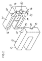
- the disk housing 1 comprises two symmetrical semicircular plates 2, 3 which are peripherally provided with holes in mutually different positions; the first semicircular plate has three holes 4, while the second semicircular plate has two holes 5; said holes are meant for screws for fixing to the two faces of a perimetric support 6, and the semicircular plates are arranged parallel to each other and form, together with the support, a sort of flat box.
- the semicircular plates 2, 3 are substantially shaped like half of a regular polygon and have, at the diagonal from which the cutting disk blade D protrudes, respective edges 7 and 8 which are folded inward: the perimetric support 6, which is advantageously formed by molding materials such as the plastics known by the trade-name Nylon, has, on its two faces, respective external ridges 9 and 10 for the interlock coupling of the polygonal edges of the semicircular plates 2, 3.
- the perimetric support 6 is provided with interlock coupling means for a water supply duct 11 and for a nozzle 12 for spraying water onto the disk blade.
- the nozzle 12 is substantially fork-shaped in order to wrap around the disk and has water passage openings which are directed toward the inside of its prongs.
- the nozzle 12 is produced by molding materials such as the plastics known by the trade-name Nylon and is constituted by two symmetrical half-shells 13 and 14 which are fork-shaped and can be coupled together by interlocking through the insertion of corresponding pins 15 in corresponding holes 16; passage ducts 17 and water spray openings 18 are formed in the mutually contacting surfaces of the half-shells 13 and 14.
- the means for coupling the nozzle to the support are of the type with a tenon 19 for the base of the nozzle, which is crossed by a central hole 20 for the passage of water, and with a mortise 21 formed in the support.
- a tenon 19 for the base of the nozzle which is crossed by a central hole 20 for the passage of water, and with a mortise 21 formed in the support.
- two mutually apposite pins 22 which protrude from the nozzle, one half of said pins being formed in the half-shell 13 and the other half being formed in the half-shell 14, said pins fitting in corresponding holes 23 of the semicircular plates.
- the nozzle wraps around the cutting edge of the disk blade and that water is sprayed from all sides by means of three spraying points directly toward said disk blade; it is also noted that the nozzle can be easily disassembled and can then be opened, since it is formed by two half-shells, in order to rapidly clean the water passage ducts and openings.
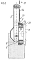
- the semicircular plate 2 is provided with means 24 for hermetic rotary coupling to the head 25 of the motor M that drives the disk blade;
- the coupling means 24 comprise a flared spacer 26 which is centrally crossed by a hole 27 for the passage of the driving shaft.
- the spacer 26 has, on one face, an annular indent 28 which snugly and rotatably fits in an opening 29 of the semicircular plate 2.
- the reference numeral 30 designates an annular washer which is crossed by four holes 31 which are distributed in an annular pattern and in which corresponding screws 32 can be inserted. Such screws 32 pass through corresponding holes 33 of the spacer 26 and screw into respective threaded holes of the head 25 of the motor; the coupling means 24 allow the disk blade housing assembly to oscillate about the axis A of the shaft of the motor of the tile cutter.
- An articulation pivot 34 for the end 35 of a metal arm 36 is screwed into a hole 34a of the semicircular plate 2; the other end 37 of the metal arm is meant to be articulated, by means of a pivot 37a, to the elements that support the disk blade driving motor, and such arm is meant to cause a coupling of the articulated-parallelogram type in order to turn the disk blade housing when the disk blade driving motor is made to oscillate in a known manner about an axis B in order to keep the disk blade covered in a safe configuration.
- the support has, at the mortise for coupling the nozzle to the support and toward the outside, a through hole 38 for the hermetic coupling of a 90° coupling 39 for connection to the duct 11.
- the duct 11 is controlled by a cock 40, which is advantageously fitted to the disk housing 2 by means of a U-shaped element 41 which has a small hole 42a for fixing to one of the screws of the holes 4 and a wide opening 42b for the passage of the wings of the cock 40.
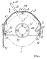
- the thicker region continues with a portion 47 crossed by a hole 48 which is arranged radially with respect to the half-disk and is meant to accommodate a screw 49 for fixing, by means of a reinforcement plate 50 and a nut 51, a spray guard flap 52 made of a spongy material suitable to absorb sprays.
- the portion 47 has a notch 53 for the rotation-preventing coupling of the hexagonal head of the screw 49 or rather of the corresponding nut 51.
- arrow 54 which is formed in relief and indelibly indicates the direction of rotation of the cutting disk blade.
Landscapes
- Engineering & Computer Science (AREA)
- Mechanical Engineering (AREA)
- Life Sciences & Earth Sciences (AREA)
- Mining & Mineral Resources (AREA)
- Wood Science & Technology (AREA)
- Forests & Forestry (AREA)
- Processing Of Stones Or Stones Resemblance Materials (AREA)
- Perforating, Stamping-Out Or Severing By Means Other Than Cutting (AREA)
- Finish Polishing, Edge Sharpening, And Grinding By Specific Grinding Devices (AREA)
- Sawing (AREA)
- Grinding-Machine Dressing And Accessory Apparatuses (AREA)
- Harvester Elements (AREA)
- Road Repair (AREA)
- Fluid-Pressure Circuits (AREA)
- Mirrors, Picture Frames, Photograph Stands, And Related Fastening Devices (AREA)
- Motor Or Generator Cooling System (AREA)
Claims (13)
- Outil de coupe électrique comprenant :- un carter (1) de disque pour une lame circulaire (D) refroidie à l'eau ;- un moteur (M) pour entraîner ladite lame circulaire (D) autour d'un axe de rotation (A) ;- un bras (36) ayant une première extrémité (35) s'articulant avec ledit carter (1) de disque et une deuxième extrémité (37) s'articulant avec un élément de support supportant ledit moteur (M), ledit bras (36) faisant tourner ledit carter (1) de disque de manière à maintenir ladite larme circulaire (D) dans une configuration sans risques lorsqu'il se produit une oscillation dudit moteur (M) ;- une buse (12) pour pulvériser de l'eau sur ladite lame circulaire (D) ; et- des moyens de couplage de verrouillage pour coupler ladite buse (12) audit carter (1) de disque ;caractérisé en ce que ladite buse (12) comprend deux demi-coques (13, 14) qui peuvent être raccordées l'une à l'autre, des conduits (17) de passage et des ouvertures (18) de pulvérisation d'eau étant formés dans des surfaces mutuellement en contact desdites demi-coques (13, 14).
- Outil de coupe électrique selon la revendication 1, et comprenant en outre un pivot d'articulation (34) reliant ladite première extrémité (35) audit carter (1) de disque et un pivot d'articulation supplémentaire (37a) reliant ladite deuxième extrémité (37) audit élément de support de telle sorte que ledit bras (36) définisse un couplage de type à parallélogramme articulé.
- Outil de coupe électrique selon la revendication 1 ou 2, et comprenant en outre des moyens de couplage (24) qui permettent audit carter de disque d'osciller autour dudit axe (A).
- Outil de coupe électrique selon la revendication 3, dans lequel lesdits moyens de couplage (24) comprennent un élément d'écartement (26) qui est traversé centralement par un trou (27) destiné au passage d'un arbre d'entrainement dudit moteur (M).
- Outil de coupe électrique selon la revendication 4, dans lequel ledit élément d'écartement (26) possède, sur une face, une empreinte annulaire (28) qui s'ajuste avec frottement doux et rotativement dans une ouverture (29) dudit carter (1) de disque.
- Outil de coupe électrique selon l'une quelconque des revendications 4 ou 5, dans lequel lesdits moyens de couplage (24) comprennent en outre une rondelle annulaire (30) qui est traversée par des trous (31) dans lesquels peuvent être insérées des vis correspondantes (32), lesdites vis (32) traversant des trous correspondants (33) dudit élément d'écartement (26) et se vissant dans des trous respectifs d'une tête (25) dudit moteur (M).
- Outil de coupe électrique selon la revendication 6, dans lequel lesdits moyens de couplage de verrouillage comprennent un réceptacle (21) formé dans ledit carter (1) de disque et configuré de manière à recevoir une portion de base (19) de ladite buse (12).
- Outil de coupe électrique selon l'une quelconque des revendications précédentes, dans lequel lesdits moyens de couplage de verrouillage comprennent en outre des goupilles (22) faisant saillie de ladite buse (12) et s'insérant dans des orifices correspondants (23) ménagés dans ledit carter (1) de disque.
- Outil de coupe électrique selon l'une quelconque des revendications précédentes, dans lequel ladite buse (12) est sensiblement en forme de fourche de manière à s'envelopper autour de ladite lame circulaire (D).
- Outil de coupe électrique selon la revendication 9, dans lequel lesdites ouvertures (18) de pulvérisation d'eau sont orientées vers l'intérieur des branches de ladite buse (12).
- Outil de coupe électrique selon l'une quelconque des revendications précédentes, dans lequel lesdites demi-coques (13, 14) peuvent être accouplées l'une à l'autre par verrouillage réciproque par insertion de goupilles correspondantes (15) dans des trous correspondants (16).
- Outil de coupe électrique selon l'une quelconque des revendications précédentes, dans lequel, sur une partie dudit carter (1) de disque qui se trouve à l'opposé d'une autre partie où est fixée ladite buse (16), se trouve une portion (47) plus épaisse qui est traversée par un trou (48) pour une vis (49) destinée à la fixation d'un rabat anti-aspersion fait d'un matériau spongieux.
- Outil de coupe électrique selon l'une quelconque des revendications précédentes, dans lequel, sur une surface exposée dudit carter (1) de disque, se trouve une flèche (54) en relief qui sert à indiquer le sens de rotation de ladite lame circulaire (D).
Applications Claiming Priority (3)
| Application Number | Priority Date | Filing Date | Title |
|---|---|---|---|
| ITBO980291 | 1998-05-07 | ||
| IT98BO000291A IT1300015B1 (it) | 1998-05-07 | 1998-05-07 | Copridisco per taglierina elettrica con raffreddamento del disco ad acqua. |
| EP99107406A EP0955119B1 (fr) | 1998-05-07 | 1999-04-26 | Carter pour machine de coupe électrique à lame de coupe refroidie par eau |
Related Parent Applications (2)
| Application Number | Title | Priority Date | Filing Date |
|---|---|---|---|
| EP99107406A Division EP0955119B1 (fr) | 1998-05-07 | 1999-04-26 | Carter pour machine de coupe électrique à lame de coupe refroidie par eau |
| EP99107406.3 Division | 1999-04-26 |
Publications (3)
| Publication Number | Publication Date |
|---|---|
| EP1547713A2 EP1547713A2 (fr) | 2005-06-29 |
| EP1547713A3 EP1547713A3 (fr) | 2005-11-02 |
| EP1547713B1 true EP1547713B1 (fr) | 2012-01-11 |
Family
ID=11343163
Family Applications (2)
| Application Number | Title | Priority Date | Filing Date |
|---|---|---|---|
| EP99107406A Expired - Lifetime EP0955119B1 (fr) | 1998-05-07 | 1999-04-26 | Carter pour machine de coupe électrique à lame de coupe refroidie par eau |
| EP04021782A Expired - Lifetime EP1547713B1 (fr) | 1998-05-07 | 1999-04-26 | Machine de coupe électrique à lame de coupe refroidie par eau |
Family Applications Before (1)
| Application Number | Title | Priority Date | Filing Date |
|---|---|---|---|
| EP99107406A Expired - Lifetime EP0955119B1 (fr) | 1998-05-07 | 1999-04-26 | Carter pour machine de coupe électrique à lame de coupe refroidie par eau |
Country Status (5)
| Country | Link |
|---|---|
| EP (2) | EP0955119B1 (fr) |
| AT (2) | ATE285310T1 (fr) |
| DE (1) | DE69922734T2 (fr) |
| ES (2) | ES2234181T3 (fr) |
| IT (1) | IT1300015B1 (fr) |
Families Citing this family (5)
| Publication number | Priority date | Publication date | Assignee | Title |
|---|---|---|---|---|
| US7281535B2 (en) * | 2004-02-23 | 2007-10-16 | Towa Intercon Technology, Inc. | Saw singulation |
| FR2868348B1 (fr) * | 2004-04-05 | 2007-06-29 | Tecma Soc Par Actions Simplifi | Module de sciage |
| ES2324381B1 (es) * | 2007-04-20 | 2010-05-26 | Raquel Durban Asensio (1/3) | Carcasa protectora de la herramienta de corte para maquinas cortadoras para la construccion. |
| EP2965886B1 (fr) | 2014-06-18 | 2020-12-02 | Husqvarna AB | Carreau ou ensemble scie de maçonnerie présentant une capacité améliorée de mouillage de lame |
| CN107639702A (zh) * | 2017-10-31 | 2018-01-30 | 天津三田协楔科技股份有限公司 | 一种自动工作台切割装置 |
Family Cites Families (13)
| Publication number | Priority date | Publication date | Assignee | Title |
|---|---|---|---|---|
| GB826194A (en) * | 1956-05-28 | 1959-12-31 | Bull Sa Machines | Improvements relating to cooling systems for machine tools |
| US2876810A (en) * | 1958-03-04 | 1959-03-10 | Joseph M Peterson | Point of operation saw guard |
| FR1242791A (fr) | 1959-06-02 | 1960-09-30 | Felker Mfg Co | Scie |
| US2972344A (en) | 1959-10-19 | 1961-02-21 | Felker Mfg Co | Adjustable mounting for rotary saw |
| FR1600356A (fr) * | 1968-01-09 | 1970-07-20 | ||
| DE2060694C3 (de) * | 1970-12-10 | 1974-05-02 | Hutton Norman Horatio | Schutzhaube fuer eine am Umfang wirkende Schleifscheibe |
| DE2904685A1 (de) * | 1979-02-08 | 1980-08-21 | Mey Kg Maschf Mafell | Kreissaege |
| US4414783A (en) * | 1981-08-19 | 1983-11-15 | Buehler Ltd. | Coolant system for rotating blade cutter |
| DE8137765U1 (de) * | 1981-12-24 | 1982-07-01 | Festo-Maschinenfabrik Gottlieb Stoll, 7300 Esslingen | Handkreissaege, insbesondere zum zerschneiden von asbest oder acrylglas- bzw. plexiglasplatten bzw. -stuecken, beschichteten formstuecken od.dgl. |
| US4676557A (en) * | 1984-07-20 | 1987-06-30 | Cimline, Inc. | Cooling system for wheeled saw |
| US4619081A (en) * | 1985-02-28 | 1986-10-28 | General Signal Corporation | Combined nozzle with air foil |
| JP2517369Y2 (ja) * | 1990-06-21 | 1996-11-20 | リョービ株式会社 | 卓上切断機 |
| DE29802546U1 (de) * | 1998-02-14 | 1998-04-23 | Lissmac Maschinenbau und Diamantwerkzeuge GmbH, 88410 Bad Wurzach | Vorrichtung zum Sägen |
-
1998
- 1998-05-07 IT IT98BO000291A patent/IT1300015B1/it active IP Right Grant
-
1999
- 1999-04-26 AT AT99107406T patent/ATE285310T1/de active
- 1999-04-26 EP EP99107406A patent/EP0955119B1/fr not_active Expired - Lifetime
- 1999-04-26 ES ES99107406T patent/ES2234181T3/es not_active Expired - Lifetime
- 1999-04-26 DE DE69922734T patent/DE69922734T2/de not_active Expired - Lifetime
- 1999-04-26 AT AT04021782T patent/ATE540772T1/de active
- 1999-04-26 EP EP04021782A patent/EP1547713B1/fr not_active Expired - Lifetime
- 1999-04-26 ES ES04021782T patent/ES2380615T3/es not_active Expired - Lifetime
Also Published As
| Publication number | Publication date |
|---|---|
| DE69922734D1 (de) | 2005-01-27 |
| DE69922734T2 (de) | 2005-12-08 |
| EP1547713A2 (fr) | 2005-06-29 |
| ES2380615T3 (es) | 2012-05-16 |
| EP0955119B1 (fr) | 2004-12-22 |
| EP0955119A2 (fr) | 1999-11-10 |
| ITBO980291A1 (it) | 1999-11-07 |
| ATE285310T1 (de) | 2005-01-15 |
| IT1300015B1 (it) | 2000-04-04 |
| ATE540772T1 (de) | 2012-01-15 |
| ITBO980291A0 (it) | 1998-05-07 |
| EP1547713A3 (fr) | 2005-11-02 |
| ES2234181T3 (es) | 2005-06-16 |
| EP0955119A3 (fr) | 2001-10-10 |
Similar Documents
| Publication | Publication Date | Title |
|---|---|---|
| US7926398B2 (en) | Cutter with optical alignment system | |
| US6405624B2 (en) | Splitter and cutting member guard assembly | |
| EP1663575B1 (fr) | Machine-outil portative a capuchon protecteur | |
| US5662428A (en) | Shaft assembly | |
| US5953820A (en) | Chisels and scrapers with replaceable blades | |
| CA1138305A (fr) | Monture a garde pour scie mecanique a onglets | |
| US20040221704A1 (en) | Cutting apparatus with a light-emitting unit for alignment of a workpiece | |
| CA1130173A (fr) | Scie circulaire pour la coupe a onglet | |
| US20110314681A1 (en) | Work head for a rotational brush cutter | |
| EP1547713B1 (fr) | Machine de coupe électrique à lame de coupe refroidie par eau | |
| AU2002224981B2 (en) | Beating arrangement | |
| CA2030881A1 (fr) | Pompe pour eaux usees, avec couteaux auto-reglables | |
| EP4268567A1 (fr) | Fixation de roue pour outil de jardin | |
| US7980163B2 (en) | Air deflector assemblies for miter saws | |
| EP1190821A3 (fr) | Couteaux basculants à lame simple ainsi que procédé de coupe avec de tels couteaux | |
| US4749014A (en) | Cutterhead for a power planer | |
| GR3033625T3 (en) | Rotary cutters. | |
| US5331743A (en) | Tile saw apparatus | |
| US20060101967A1 (en) | Greater capacity cutting saw | |
| CN219311484U (zh) | 一种具有新型锯割角度调节件的带锯底座 | |
| CN201319767Y (zh) | 花园工具 | |
| CN101176999A (zh) | 切割装置和与该切割装置一起使用的激光模块 | |
| US20070050993A1 (en) | Jigsaw with a rotating handle | |
| CN222115614U (zh) | 一种用于房屋装修的管道开槽装置 | |
| AU680333B2 (en) | Twin blade saw |
Legal Events
| Date | Code | Title | Description |
|---|---|---|---|
| PUAI | Public reference made under article 153(3) epc to a published international application that has entered the european phase |
Free format text: ORIGINAL CODE: 0009012 |
|
| AC | Divisional application: reference to earlier application |
Ref document number: 0955119 Country of ref document: EP Kind code of ref document: P |
|
| AK | Designated contracting states |
Kind code of ref document: A2 Designated state(s): AT DE ES FR GB IT |
|
| PUAL | Search report despatched |
Free format text: ORIGINAL CODE: 0009013 |
|
| AK | Designated contracting states |
Kind code of ref document: A3 Designated state(s): AT DE ES FR GB IT |
|
| RIC1 | Information provided on ipc code assigned before grant |
Ipc: 7B 28D 1/04 B Ipc: 7B 23D 59/02 A Ipc: 7B 27G 19/02 B |
|
| 17P | Request for examination filed |
Effective date: 20060427 |
|
| AKX | Designation fees paid |
Designated state(s): AT DE ES FR GB IT |
|
| 17Q | First examination report despatched |
Effective date: 20060713 |
|
| GRAP | Despatch of communication of intention to grant a patent |
Free format text: ORIGINAL CODE: EPIDOSNIGR1 |
|
| GRAS | Grant fee paid |
Free format text: ORIGINAL CODE: EPIDOSNIGR3 |
|
| GRAA | (expected) grant |
Free format text: ORIGINAL CODE: 0009210 |
|
| RIN1 | Information on inventor provided before grant (corrected) |
Inventor name: TONDINI, CLAUDIO |
|
| AC | Divisional application: reference to earlier application |
Ref document number: 0955119 Country of ref document: EP Kind code of ref document: P |
|
| AK | Designated contracting states |
Kind code of ref document: B1 Designated state(s): AT DE ES FR GB IT |
|
| REG | Reference to a national code |
Ref country code: GB Ref legal event code: FG4D |
|
| REG | Reference to a national code |
Ref country code: AT Ref legal event code: REF Ref document number: 540772 Country of ref document: AT Kind code of ref document: T Effective date: 20120115 |
|
| REG | Reference to a national code |
Ref country code: DE Ref legal event code: R096 Ref document number: 69943982 Country of ref document: DE Effective date: 20120315 |
|
| REG | Reference to a national code |
Ref country code: DE Ref legal event code: R082 Ref document number: 69943982 Country of ref document: DE Representative=s name: WITTE, WELLER & PARTNER, DE Ref country code: DE Ref legal event code: R082 Ref document number: 69943982 Country of ref document: DE Representative=s name: WITTE, WELLER & PARTNER PATENTANWAELTE MBB, DE |
|
| REG | Reference to a national code |
Ref country code: ES Ref legal event code: FG2A Ref document number: 2380615 Country of ref document: ES Kind code of ref document: T3 Effective date: 20120516 |
|
| PLBE | No opposition filed within time limit |
Free format text: ORIGINAL CODE: 0009261 |
|
| STAA | Information on the status of an ep patent application or granted ep patent |
Free format text: STATUS: NO OPPOSITION FILED WITHIN TIME LIMIT |
|
| 26N | No opposition filed |
Effective date: 20121012 |
|
| PGFP | Annual fee paid to national office [announced via postgrant information from national office to epo] |
Ref country code: ES Payment date: 20120330 Year of fee payment: 14 |
|
| REG | Reference to a national code |
Ref country code: DE Ref legal event code: R097 Ref document number: 69943982 Country of ref document: DE Effective date: 20121012 |
|
| PGFP | Annual fee paid to national office [announced via postgrant information from national office to epo] |
Ref country code: AT Payment date: 20120425 Year of fee payment: 14 |
|
| PGFP | Annual fee paid to national office [announced via postgrant information from national office to epo] |
Ref country code: GB Payment date: 20130326 Year of fee payment: 15 |
|
| PGFP | Annual fee paid to national office [announced via postgrant information from national office to epo] |
Ref country code: DE Payment date: 20130322 Year of fee payment: 15 |
|
| PGFP | Annual fee paid to national office [announced via postgrant information from national office to epo] |
Ref country code: IT Payment date: 20130423 Year of fee payment: 15 Ref country code: FR Payment date: 20130603 Year of fee payment: 15 |
|
| REG | Reference to a national code |
Ref country code: DE Ref legal event code: R119 Ref document number: 69943982 Country of ref document: DE |
|
| REG | Reference to a national code |
Ref country code: AT Ref legal event code: MM01 Ref document number: 540772 Country of ref document: AT Kind code of ref document: T Effective date: 20140426 |
|
| GBPC | Gb: european patent ceased through non-payment of renewal fee |
Effective date: 20140426 |
|
| REG | Reference to a national code |
Ref country code: FR Ref legal event code: ST Effective date: 20141231 |
|
| REG | Reference to a national code |
Ref country code: DE Ref legal event code: R119 Ref document number: 69943982 Country of ref document: DE Effective date: 20141101 |
|
| PG25 | Lapsed in a contracting state [announced via postgrant information from national office to epo] |
Ref country code: GB Free format text: LAPSE BECAUSE OF NON-PAYMENT OF DUE FEES Effective date: 20140426 Ref country code: DE Free format text: LAPSE BECAUSE OF NON-PAYMENT OF DUE FEES Effective date: 20141101 |
|
| PG25 | Lapsed in a contracting state [announced via postgrant information from national office to epo] |
Ref country code: AT Free format text: LAPSE BECAUSE OF NON-PAYMENT OF DUE FEES Effective date: 20140426 Ref country code: FR Free format text: LAPSE BECAUSE OF NON-PAYMENT OF DUE FEES Effective date: 20140430 |
|
| PG25 | Lapsed in a contracting state [announced via postgrant information from national office to epo] |
Ref country code: IT Free format text: LAPSE BECAUSE OF NON-PAYMENT OF DUE FEES Effective date: 20140426 |
|
| PG25 | Lapsed in a contracting state [announced via postgrant information from national office to epo] |
Ref country code: ES Free format text: LAPSE BECAUSE OF NON-PAYMENT OF DUE FEES Effective date: 20140427 |