EP1547459A1 - Messerscheibe mit Reisszähnen für einen Häcksler - Google Patents
Messerscheibe mit Reisszähnen für einen Häcksler Download PDFInfo
- Publication number
- EP1547459A1 EP1547459A1 EP04029936A EP04029936A EP1547459A1 EP 1547459 A1 EP1547459 A1 EP 1547459A1 EP 04029936 A EP04029936 A EP 04029936A EP 04029936 A EP04029936 A EP 04029936A EP 1547459 A1 EP1547459 A1 EP 1547459A1
- Authority
- EP
- European Patent Office
- Prior art keywords
- knife
- chopper
- disc
- chopper according
- blade
- Prior art date
- Legal status (The legal status is an assumption and is not a legal conclusion. Google has not performed a legal analysis and makes no representation as to the accuracy of the status listed.)
- Granted
Links
- 238000005520 cutting process Methods 0.000 title claims abstract description 35
- 239000000463 material Substances 0.000 claims description 7
- 239000011368 organic material Substances 0.000 claims description 2
- 230000002093 peripheral effect Effects 0.000 description 2
- 230000000295 complement effect Effects 0.000 description 1
- 238000010276 construction Methods 0.000 description 1
- 239000002184 metal Substances 0.000 description 1
- 238000000926 separation method Methods 0.000 description 1
- 239000002023 wood Substances 0.000 description 1
Images


Classifications
-
- A—HUMAN NECESSITIES
- A01—AGRICULTURE; FORESTRY; ANIMAL HUSBANDRY; HUNTING; TRAPPING; FISHING
- A01G—HORTICULTURE; CULTIVATION OF VEGETABLES, FLOWERS, RICE, FRUIT, VINES, HOPS OR SEAWEED; FORESTRY; WATERING
- A01G3/00—Cutting implements specially adapted for horticultural purposes; Delimbing standing trees
- A01G3/002—Cutting implements specially adapted for horticultural purposes; Delimbing standing trees for comminuting plant waste
-
- B—PERFORMING OPERATIONS; TRANSPORTING
- B02—CRUSHING, PULVERISING, OR DISINTEGRATING; PREPARATORY TREATMENT OF GRAIN FOR MILLING
- B02C—CRUSHING, PULVERISING, OR DISINTEGRATING IN GENERAL; MILLING GRAIN
- B02C18/00—Disintegrating by knives or other cutting or tearing members which chop material into fragments
- B02C18/06—Disintegrating by knives or other cutting or tearing members which chop material into fragments with rotating knives
- B02C18/08—Disintegrating by knives or other cutting or tearing members which chop material into fragments with rotating knives within vertical containers
- B02C18/083—Disintegrating by knives or other cutting or tearing members which chop material into fragments with rotating knives within vertical containers with a disc rotor having generally radially extending slots or openings bordered with cutting knives
-
- B—PERFORMING OPERATIONS; TRANSPORTING
- B02—CRUSHING, PULVERISING, OR DISINTEGRATING; PREPARATORY TREATMENT OF GRAIN FOR MILLING
- B02C—CRUSHING, PULVERISING, OR DISINTEGRATING IN GENERAL; MILLING GRAIN
- B02C18/00—Disintegrating by knives or other cutting or tearing members which chop material into fragments
- B02C18/06—Disintegrating by knives or other cutting or tearing members which chop material into fragments with rotating knives
- B02C18/16—Details
- B02C18/18—Knives; Mountings thereof
Definitions
- the invention relates to a shredder for crushing organic material, in particular garden shredders for branches, Scrub or the like. According to the preamble of the claim 1.
- Such shredders are well known. On a rotating Knife disc is at least one chopper knife attached, the one extending approximately in the radial direction Cutting edge and with a housing fixed Stop cooperates to introduced into the knife chamber Shred material.
- the shredder should both small branches, scrub, larger branches and the like in such a way shred that the clippings are easily composted can. This sets a sufficiently fine comminution of Cuttings ahead.
- the invention is based on the object, a generic To develop shredders such that regardless of the inserted into the knife chamber material a uniform, fine comminution is guaranteed.
- the arranged in the region of the outer periphery of the knife disc Fracture knife causes a material cut in the direction of rotation the rotating blade disc, so that the clippings Approximately perpendicular to the section of the subsequent chopper blade is cut. This is a sufficiently fine crushing both pruned clippings and of fine and coarse branches and other possible.
- the razor is in the circumferential direction of Knife disc aligned, being at the leading edge the cutting knife a front cutting edge is formed.
- expedient is complementary to extending in the circumferential direction Roof edge of the tearing knife a roof cutting edge designed so that a good shredding of the material given is.
- the tearing knife extends over the cutting plane of the Chopper out, so that the cut of the tearing knife goes deeper than the cutting plane of the chopper, which a clean separation of a single wood chip is guaranteed by the material to be shredded.
- the shredder is - like the chopper - a housing stronger Assigned stop, with which the knife cooperates.
- the chopper associated stop and the the tearing knife associated stop are preferably at one formed common component, wherein the component is preferably Part of a hopper to the knife chamber is.
- the cutter disk 1 shown in Figs. 1 to 5 is with a central opening 2 on a non-illustrated Drive shaft of a drive motor rotatably mounted.
- to Rotational drive can be provided more openings 3.
- the illustrated blade has with respect to its axis of rotation 4 diametrically opposed radial slots 5, which are open to the circumference 6 of the cutter disk 1.
- trailing edge 8 of the radial slots. 5 has a knife holder 9, in which a chopper knife 10 is received and fixed with a cutting edge 16.
- the Cutting 16 chopping knives determine a cutting plane 34 ( Figure 6).
- the cutter disk 1 also has two rupture blades 20, in the circumferential direction 11 with a circumferential distance u to respective chopping blades 10 are.
- the arrangement is advantageous made such that in the direction of rotation 7 each one Dicing knife 20 precedes the chopper blade 10.
- the knife 20 is located or its leading edge 25 is based on the chopper blade 10 approximately at its outer circle diameter;
- the tear blade 20 is slightly in the circle diameter.
- Each razor 20 has a main body 21 (FIG. 4) which - As Figs. 2 and 3 show - at an angle 22 to Rotary axis 4 can lie.
- the razor 20 is with a radial attachment portion 23 on the bottom 12 of the Knife disc 1 is fixed, wherein the attachment portion 23 approximately radially to the axis of rotation 4 and approximately parallel extends to the plane of the cutter disk 1.
- Figs. 1, 2 and Figure 5 shows the attachment portion 23 of the tear gauge 20 in an area on the bottom 12 of Knife disc 1 fixed in the fixed an additional sheet 14 is.
- the additional sheet 14 has a circular segment-shaped Form and extends approximately symmetrically between the radial slots 5, wherein the additional sheet 15 near the outer periphery 6 fixed on the bottom 12 of the cutter disk 1 is.
- the formed in the manner of a Fangzzzzer 20 extends on the attachment portion 23 from the bottom 12 of the cutter disk 1 through a recess 15 in the peripheral edge 6 of the cutter disk 1 through the top 13th the knife disc out (Fig. 2, 3), wherein the roof edge 24 of the cutting blade 20 over the 16 through the cutting Chopping knife 10 protrude certain section plane 34.
- the Additional sheet 14 is preferably a sound-absorbing Sheet metal, which in sandwich construction on the cutting disc 1 is attached.
- each tear blade 20 is approximately in the circumferential direction 11 of the cutter disk 1 aligned, wherein the leading edge 7 in the direction of rotation 25 as a front cutting edge the tear gauge 20 is formed.
- the in the circumferential direction 11 aligned roof edge 24 of the Main body 21 of the tearing knife 20 can be used as a roof cutting edge Be formed over the cutting plane of the chopper 10 survives. It may be appropriate, even the form trailing edge of the body 21 as a cutting edge.
- the blade disc 1 has a sawtooth-like Outer diameter 6, i. on the outer circumference 6 is at least one or more height jumps a are formed.
- the height jump a is in the embodiment respectively in the area of a chopper blade 10 or a tear blade 20 and is preferably by differently long radial edges of a blade associated radial slot 5 and the recess 15 created. So is the direction of rotation leading edge of the radial slot 5 and the recess 15 formed by the height jump a shorter than the trailing Longitudinal edge 8 of the radial slot 5 and the trailing Longitudinal edge 18 of the outer periphery 6 open recess 15.
- a Räumeriel 17 arranged, the - as Figs. 2, 3 and 5 show - approximately at right angles from the bottom 12 of the Knife disc 1 protrudes and to promote the cuttings is provided from the knife chamber 28.
- the Räumeriel 17 extends over substantially the entire Length of the attachment portion 23 at the trailing Longitudinal edge 19 and forms together with the attachment portion 23 and the doctor blade 20 a common, preferably a one-piece component.
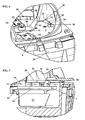
- the chopper blade 10 and the doctor blade 20 is respectively a stop 30 or 31 associated with the respective Knife 10, 20 cooperates, and on a housing fixed Component 26 is provided. As shown in FIGS. 6 and 7, extends itself the chopper 10 associated stop 31 approximately at the height of the cutting plane 34 above the top 13 of the knife disc 1.
- the fence knife 20 associated housing fixed stop 31st is also above in the peripheral region of the cutter disk 1 the top 13 and acts with the front cutting edge trained leading edge 25 cutting together. It may be appropriate to another associated with the breaking knife 20 Stop 32, which is from the upright Stop 31 above the cutter disk 1 in the circumferential direction extends to a section outside the outer periphery of the cutter disk 1 is located. This stop 32 can be advantageous with the trained as a roof cutting Roof edge 24 intersecting cutting.
- the stops 30, 31 and 32 are on a common component 26 formed, which part of a hopper to the knife chamber 28 is.
- the housing-fixed component 26 is positively with the housing pot 29 of the knife chamber 28th connected so that the cut on the stops 30, 31 acting forces from the housing pot 29 of the knife chamber 28th are included.
- the hopper 27 forms so with a the housing pot 29 force-transmitting connected component.
- the central razor 40 is by rotation stops 42 of the Blade 1 rotatably held on the top 13.
- the knife ends 41 can advantageously up into the cutting area the chopping knife 10 protrude.
Landscapes
- Life Sciences & Earth Sciences (AREA)
- Engineering & Computer Science (AREA)
- Food Science & Technology (AREA)
- Biodiversity & Conservation Biology (AREA)
- Ecology (AREA)
- Forests & Forestry (AREA)
- Environmental Sciences (AREA)
- Crushing And Pulverization Processes (AREA)
- Food-Manufacturing Devices (AREA)
- Dental Tools And Instruments Or Auxiliary Dental Instruments (AREA)
Abstract
Description
- Fig. 1
- eine Draufsicht auf eine erfindungsgemäße Messerscheibe von unten,
- Fig. 2
- einen Schnitt längs der Linie II-II in Fig. 1,
- Fig. 3
- eine Seitenansicht der Messerscheibe nach Fig. 1,
- Fig. 4
- eine perspektivische Ansicht der Messerscheibe nach Fig. 1 von oben,
- Fig. 5
- eine perspektivische Ansicht der erfindungsgemäßen Messerscheibe von unten,
- Fig. 6
- eine Teildarstellung einer Messerkammer mit darin angeordneter Messerscheibe nach Fig. 1,
- Fig. 7
- einen Teilschnitt durch eine Messerkammer nach Fig. 6.
Claims (16)
- Häcksler zum Zerkleinern von organischem Material, insbesondere Gartenhäcksler für Astwerk, Gestrüpp oder dgl., bestehend aus einer Messerkammer (28) mit einer rotierenden Messerscheibe (1), auf der mindestens ein Häckselmesser (10) befestigt ist, und das Häckselmesser (10) eine sich etwa in Radialrichtung erstreckende Schneide (16) aufweist, wobei das Häckselmesser (10) zum Zerkleinern des Materials mit einem gehäusefesten Anschlag (30) zusammenwirkt,
dadurch gekennzeichnet, daß im Bereich des Außenumfangs (6) der Messerscheibe (1) ein Reißmesser (20) angeordnet ist, das in Umfangsrichtung (11) der Messerscheibe (1) mit Abstand (u) zum Häckselmesser liegt. - Häcksler nach Anspruch 1,
dadurch gekennzeichnet, daß der Grundkörper (21) des Reißmessers (20) in Umfangsrichtung (11) der Messerscheibe (1) ausgerichtet liegt. - Häcksler nach Anspruch 1 oder 2,
dadurch gekennzeichnet, daß an einer vorlaufenden Kante (25) des Grundkörpers (21) des Reißmessers (20) eine Frontschneide ausgebildet ist. - Häcksler nach einem der Ansprüche 1 bis 3,
dadurch gekennzeichnet, daß an einer in Umfangsrichtung (11) sich erstreckenden Dachkante (24) des Grundkörpers (21) des Reißmessers (20) eine Dachschneide ausgebildet ist. - Häcksler nach einem der Ansprüche 1 bis 4,
dadurch gekennzeichnet, daß das Reißmesser (20) über die Schnittebene (34) des Häckselmessers (10) übersteht. - Häcksler nach einem der Ansprüche 1 bis 5,
dadurch gekennzeichnet, daß das Reißmesser (10) in einer Umfangsausnehmung (15) der Messerscheibe (1) liegt. - Häcksler nach einem der Ansprüche 1 bis 6,
dadurch gekennzeichnet, daß sich das Reißmesser (20) von der Unterseite (12) der Messerscheibe (1) über dessen Oberseite (13) hinaus erstreckt. - Häcksler nach einem der Ansprüche 1 bis 7,
dadurch gekennzeichnet, daß das Reißmesser (20) mit einem sich etwa parallel zur Messerscheibe (1) erstreckenden Befestigungsabschnitt (23) an der Messerscheibe (1) festgelegt ist. - Häcksler nach Anspruch 8,
dadurch gekennzeichnet, daß sich der Befestigungsabschnitt (23) etwa radial zur Messerscheibe (1) erstreckt. - Häcksler nach einem der Ansprüche 1 bis 9,
dadurch gekennzeichnet, daß das Reißmesser (20) in einem Bereich der Messerscheibe (1) befestigt ist, in dem die Messerscheibe (1) ein Zusatzblech (15) trägt. - Häcksler nach Anspruch 10,
dadurch gekennzeichnet, daß das Zusatzblech (14) ein geräuschdämmendes Blech ist. - Häcksler nach einem der Ansprüche 1 bis 11,
dadurch gekennzeichnet, daß dem Reißmesser (20) ein gehäusefester Anschlag (31, 32) zugeordnet ist. - Häcksler nach Anspruch 12,
dadurch gekennzeichnet, daß der dem Häckselmesser (10) zugeordnete Anschlag (30) und der dem Reißmesser (20) zugeordnete Anschlag (31, 32) an einem gemeinsamen Bauteil (26) der Messerkammer (28) ausgebildet sind. - Häcksler nach Anspruch 13,
dadurch gekennzeichnet, daß das Bauteil (26) Teil eines Einfülltrichters (27) zur Messerkammer (28) ist. - Häcksler nach Anspruch 8 oder 9,
dadurch gekennzeichnet, daß das Reißmesser (20), sein Befestigungsabschnitt (23) und ein Räumflügel (17) ein gemeinsames Bauteil bilden. - Häcksler nach Anspruch 15,
dadurch gekennzeichnet, daß der Reißzahn (20), sein Befestigungsabschnitt (23) und ein Räumflügel (17) ein einteiliges Bauteil bilden.
Applications Claiming Priority (2)
| Application Number | Priority Date | Filing Date | Title |
|---|---|---|---|
| DE20320044U DE20320044U1 (de) | 2003-12-24 | 2003-12-24 | Messerscheibe mit Reißzähnen für einen Häcksler |
| DE20320044U | 2003-12-24 |
Publications (2)
| Publication Number | Publication Date |
|---|---|
| EP1547459A1 true EP1547459A1 (de) | 2005-06-29 |
| EP1547459B1 EP1547459B1 (de) | 2009-05-27 |
Family
ID=31984906
Family Applications (1)
| Application Number | Title | Priority Date | Filing Date |
|---|---|---|---|
| EP04029936A Expired - Lifetime EP1547459B1 (de) | 2003-12-24 | 2004-12-17 | Messerscheibe mit Reisszähnen für einen Häcksler |
Country Status (4)
| Country | Link |
|---|---|
| EP (1) | EP1547459B1 (de) |
| AT (1) | ATE432004T1 (de) |
| DE (2) | DE20320044U1 (de) |
| ES (1) | ES2326476T3 (de) |
Cited By (3)
| Publication number | Priority date | Publication date | Assignee | Title |
|---|---|---|---|---|
| CN107442224A (zh) * | 2016-05-30 | 2017-12-08 | 珠海格力电器股份有限公司 | 研磨盘结构及食物垃圾处理器 |
| CN110787883A (zh) * | 2019-12-13 | 2020-02-14 | 西部新锆核材料科技有限公司 | 一种锆合金屑料破碎机破碎装置 |
| CN111450958A (zh) * | 2019-01-21 | 2020-07-28 | 上海盛晟机械有限公司 | 一种破碎刀盘 |
Families Citing this family (3)
| Publication number | Priority date | Publication date | Assignee | Title |
|---|---|---|---|---|
| FR2948582B1 (fr) * | 2009-07-31 | 2011-08-19 | Kiva | Dispositif de broyage des vegetaux. |
| EP2564930B1 (de) * | 2011-08-30 | 2013-12-18 | Viking GmbH | Häcksler |
| AT516805B1 (de) * | 2015-02-02 | 2016-11-15 | Kesla Oyj | Gebläse einer Hackmaschine |
Citations (4)
| Publication number | Priority date | Publication date | Assignee | Title |
|---|---|---|---|---|
| US3674220A (en) * | 1970-12-07 | 1972-07-04 | Omark Industries Inc | Chipper shredder |
| US4360166A (en) * | 1979-08-29 | 1982-11-23 | Firma Cornes & Co. Ohg | Motor-driven shredding apparatus particularly for garden waste |
| US4860961A (en) * | 1987-07-07 | 1989-08-29 | Crones & Co., Gmbh | Garden chipper/shredder |
| US5205498A (en) * | 1989-09-02 | 1993-04-27 | Sabo-Maschinenfabrik Aktiengesellschaft | Cutter device for wood chipper |
-
2003
- 2003-12-24 DE DE20320044U patent/DE20320044U1/de not_active Expired - Lifetime
-
2004
- 2004-12-17 ES ES04029936T patent/ES2326476T3/es not_active Expired - Lifetime
- 2004-12-17 EP EP04029936A patent/EP1547459B1/de not_active Expired - Lifetime
- 2004-12-17 DE DE502004009523T patent/DE502004009523D1/de not_active Expired - Lifetime
- 2004-12-17 AT AT04029936T patent/ATE432004T1/de active
Patent Citations (4)
| Publication number | Priority date | Publication date | Assignee | Title |
|---|---|---|---|---|
| US3674220A (en) * | 1970-12-07 | 1972-07-04 | Omark Industries Inc | Chipper shredder |
| US4360166A (en) * | 1979-08-29 | 1982-11-23 | Firma Cornes & Co. Ohg | Motor-driven shredding apparatus particularly for garden waste |
| US4860961A (en) * | 1987-07-07 | 1989-08-29 | Crones & Co., Gmbh | Garden chipper/shredder |
| US5205498A (en) * | 1989-09-02 | 1993-04-27 | Sabo-Maschinenfabrik Aktiengesellschaft | Cutter device for wood chipper |
Cited By (4)
| Publication number | Priority date | Publication date | Assignee | Title |
|---|---|---|---|---|
| CN107442224A (zh) * | 2016-05-30 | 2017-12-08 | 珠海格力电器股份有限公司 | 研磨盘结构及食物垃圾处理器 |
| CN111450958A (zh) * | 2019-01-21 | 2020-07-28 | 上海盛晟机械有限公司 | 一种破碎刀盘 |
| CN110787883A (zh) * | 2019-12-13 | 2020-02-14 | 西部新锆核材料科技有限公司 | 一种锆合金屑料破碎机破碎装置 |
| CN110787883B (zh) * | 2019-12-13 | 2024-02-13 | 西部新锆核材料科技有限公司 | 一种锆合金屑料破碎机破碎装置 |
Also Published As
| Publication number | Publication date |
|---|---|
| DE502004009523D1 (de) | 2009-07-09 |
| EP1547459B1 (de) | 2009-05-27 |
| ATE432004T1 (de) | 2009-06-15 |
| DE20320044U1 (de) | 2004-03-04 |
| ES2326476T3 (es) | 2009-10-13 |
Similar Documents
| Publication | Publication Date | Title |
|---|---|---|
| EP0416315B1 (de) | Häcksler zum Zerkleinern von Gartenabfällen mit einem Schneidwerk | |
| DE2158778A1 (de) | Zerkleinerungsvorrichtung fur Holz und Laub und dergleichen Materialien | |
| CH654493A5 (de) | Umlaufend antreibbare messertraegerscheibe fuer gartenabfall-zerkleinerungsgeraete. | |
| EP1547459B1 (de) | Messerscheibe mit Reisszähnen für einen Häcksler | |
| EP0598306B1 (de) | Häcksler, insbesondere für Haus- und Gartenabfälle | |
| EP2394743A1 (de) | Zerkleinerungsmaschine | |
| DE10350123B3 (de) | Häckselvorrichtung für einen Mähdrescher | |
| WO2021209250A1 (de) | Mulchgerät | |
| EP2564930B1 (de) | Häcksler | |
| EP0505702B1 (de) | Gartenhäcksler mit Messergehäuse und darin umlaufend anzutreibenden Flach- sowie Vorzerkleinerungsmessern | |
| EP0630686B1 (de) | Gartenabfallzerkleinerer | |
| EP0505701B1 (de) | Gartenhäcksler mit Messergehäuse und darin umlaufend anzutreibenden Flachmessern | |
| DE4427700C2 (de) | Vorrichtung zum Häckseln von Gartenabfällen | |
| EP1782680B1 (de) | Vorrichtung zum Zerkleinern von Pflanzengut in Form von Grünmasse und/oder Schwachholz | |
| DE3108045A1 (de) | Haecksler | |
| AT404435B (de) | Schneidwerk für gartenhäcksler | |
| EP0089571B1 (de) | Vorrichtung zum Zerkleinern von Schwachholz | |
| DE2424725C3 (de) | Zerkleinerungsmaschine für sperriges Gut | |
| EP2014370B1 (de) | Häcksler | |
| DE3136172A1 (de) | Vorrichtung zum zerkleinern und kompostieren von gartenabfaellen | |
| DE3245373A1 (de) | Vorrichtung zum zerkleinern von abfallholz, insbesondere stubben, zu holzschnitzeln | |
| DE3503904A1 (de) | Gartenabfall-zerkleinerungsgeraet mit vorzerkleinerungsfluegeln | |
| DE4024757A1 (de) | Haecksler zum zerkleinern von gartenabfaellen mit einem schneidwerk | |
| EP0688605B1 (de) | Messeranordnung für eine Maschine zum Zerkleinern von pflanzlichen Abfällen | |
| DE4409446C2 (de) | Rotationssymmetrischer Hobelkopf und Zerkleinerungsvorrichtung |
Legal Events
| Date | Code | Title | Description |
|---|---|---|---|
| PUAI | Public reference made under article 153(3) epc to a published international application that has entered the european phase |
Free format text: ORIGINAL CODE: 0009012 |
|
| AK | Designated contracting states |
Kind code of ref document: A1 Designated state(s): AT BE BG CH CY CZ DE DK EE ES FI FR GB GR HU IE IS IT LI LT LU MC NL PL PT RO SE SI SK TR |
|
| AX | Request for extension of the european patent |
Extension state: AL BA HR LV MK YU |
|
| 17P | Request for examination filed |
Effective date: 20050621 |
|
| AKX | Designation fees paid |
Designated state(s): AT BE BG CH CY CZ DE DK EE ES FI FR GB GR HU IE IS IT LI LT LU MC NL PL PT RO SE SI SK TR |
|
| GRAP | Despatch of communication of intention to grant a patent |
Free format text: ORIGINAL CODE: EPIDOSNIGR1 |
|
| GRAS | Grant fee paid |
Free format text: ORIGINAL CODE: EPIDOSNIGR3 |
|
| GRAA | (expected) grant |
Free format text: ORIGINAL CODE: 0009210 |
|
| AK | Designated contracting states |
Kind code of ref document: B1 Designated state(s): AT BE BG CH CY CZ DE DK EE ES FI FR GB GR HU IE IS IT LI LT LU MC NL PL PT RO SE SI SK TR |
|
| REG | Reference to a national code |
Ref country code: GB Ref legal event code: FG4D Free format text: NOT ENGLISH |
|
| REG | Reference to a national code |
Ref country code: CH Ref legal event code: EP |
|
| REG | Reference to a national code |
Ref country code: IE Ref legal event code: FG4D Free format text: LANGUAGE OF EP DOCUMENT: GERMAN |
|
| REF | Corresponds to: |
Ref document number: 502004009523 Country of ref document: DE Date of ref document: 20090709 Kind code of ref document: P |
|
| REG | Reference to a national code |
Ref country code: ES Ref legal event code: FG2A Ref document number: 2326476 Country of ref document: ES Kind code of ref document: T3 |
|
| PG25 | Lapsed in a contracting state [announced via postgrant information from national office to epo] |
Ref country code: LT Free format text: LAPSE BECAUSE OF FAILURE TO SUBMIT A TRANSLATION OF THE DESCRIPTION OR TO PAY THE FEE WITHIN THE PRESCRIBED TIME-LIMIT Effective date: 20090527 Ref country code: FI Free format text: LAPSE BECAUSE OF FAILURE TO SUBMIT A TRANSLATION OF THE DESCRIPTION OR TO PAY THE FEE WITHIN THE PRESCRIBED TIME-LIMIT Effective date: 20090527 Ref country code: PT Free format text: LAPSE BECAUSE OF FAILURE TO SUBMIT A TRANSLATION OF THE DESCRIPTION OR TO PAY THE FEE WITHIN THE PRESCRIBED TIME-LIMIT Effective date: 20090927 |
|
| NLV1 | Nl: lapsed or annulled due to failure to fulfill the requirements of art. 29p and 29m of the patents act | ||
| PG25 | Lapsed in a contracting state [announced via postgrant information from national office to epo] |
Ref country code: IS Free format text: LAPSE BECAUSE OF FAILURE TO SUBMIT A TRANSLATION OF THE DESCRIPTION OR TO PAY THE FEE WITHIN THE PRESCRIBED TIME-LIMIT Effective date: 20090927 Ref country code: NL Free format text: LAPSE BECAUSE OF FAILURE TO SUBMIT A TRANSLATION OF THE DESCRIPTION OR TO PAY THE FEE WITHIN THE PRESCRIBED TIME-LIMIT Effective date: 20090527 Ref country code: SI Free format text: LAPSE BECAUSE OF FAILURE TO SUBMIT A TRANSLATION OF THE DESCRIPTION OR TO PAY THE FEE WITHIN THE PRESCRIBED TIME-LIMIT Effective date: 20090527 Ref country code: SE Free format text: LAPSE BECAUSE OF FAILURE TO SUBMIT A TRANSLATION OF THE DESCRIPTION OR TO PAY THE FEE WITHIN THE PRESCRIBED TIME-LIMIT Effective date: 20090827 Ref country code: PL Free format text: LAPSE BECAUSE OF FAILURE TO SUBMIT A TRANSLATION OF THE DESCRIPTION OR TO PAY THE FEE WITHIN THE PRESCRIBED TIME-LIMIT Effective date: 20090527 |
|
| REG | Reference to a national code |
Ref country code: IE Ref legal event code: FD4D |
|
| PG25 | Lapsed in a contracting state [announced via postgrant information from national office to epo] |
Ref country code: IE Free format text: LAPSE BECAUSE OF FAILURE TO SUBMIT A TRANSLATION OF THE DESCRIPTION OR TO PAY THE FEE WITHIN THE PRESCRIBED TIME-LIMIT Effective date: 20090527 Ref country code: EE Free format text: LAPSE BECAUSE OF FAILURE TO SUBMIT A TRANSLATION OF THE DESCRIPTION OR TO PAY THE FEE WITHIN THE PRESCRIBED TIME-LIMIT Effective date: 20090527 Ref country code: DK Free format text: LAPSE BECAUSE OF FAILURE TO SUBMIT A TRANSLATION OF THE DESCRIPTION OR TO PAY THE FEE WITHIN THE PRESCRIBED TIME-LIMIT Effective date: 20090527 Ref country code: RO Free format text: LAPSE BECAUSE OF FAILURE TO SUBMIT A TRANSLATION OF THE DESCRIPTION OR TO PAY THE FEE WITHIN THE PRESCRIBED TIME-LIMIT Effective date: 20090527 Ref country code: CZ Free format text: LAPSE BECAUSE OF FAILURE TO SUBMIT A TRANSLATION OF THE DESCRIPTION OR TO PAY THE FEE WITHIN THE PRESCRIBED TIME-LIMIT Effective date: 20090527 |
|
| PG25 | Lapsed in a contracting state [announced via postgrant information from national office to epo] |
Ref country code: SK Free format text: LAPSE BECAUSE OF FAILURE TO SUBMIT A TRANSLATION OF THE DESCRIPTION OR TO PAY THE FEE WITHIN THE PRESCRIBED TIME-LIMIT Effective date: 20090527 |
|
| PG25 | Lapsed in a contracting state [announced via postgrant information from national office to epo] |
Ref country code: BG Free format text: LAPSE BECAUSE OF FAILURE TO SUBMIT A TRANSLATION OF THE DESCRIPTION OR TO PAY THE FEE WITHIN THE PRESCRIBED TIME-LIMIT Effective date: 20090827 |
|
| PLBE | No opposition filed within time limit |
Free format text: ORIGINAL CODE: 0009261 |
|
| STAA | Information on the status of an ep patent application or granted ep patent |
Free format text: STATUS: NO OPPOSITION FILED WITHIN TIME LIMIT |
|
| 26N | No opposition filed |
Effective date: 20100302 |
|
| PG25 | Lapsed in a contracting state [announced via postgrant information from national office to epo] |
Ref country code: MC Free format text: LAPSE BECAUSE OF NON-PAYMENT OF DUE FEES Effective date: 20100701 |
|
| REG | Reference to a national code |
Ref country code: CH Ref legal event code: PL |
|
| PG25 | Lapsed in a contracting state [announced via postgrant information from national office to epo] |
Ref country code: GR Free format text: LAPSE BECAUSE OF FAILURE TO SUBMIT A TRANSLATION OF THE DESCRIPTION OR TO PAY THE FEE WITHIN THE PRESCRIBED TIME-LIMIT Effective date: 20090828 Ref country code: LI Free format text: LAPSE BECAUSE OF NON-PAYMENT OF DUE FEES Effective date: 20091231 Ref country code: CH Free format text: LAPSE BECAUSE OF NON-PAYMENT OF DUE FEES Effective date: 20091231 |
|
| PG25 | Lapsed in a contracting state [announced via postgrant information from national office to epo] |
Ref country code: IT Free format text: LAPSE BECAUSE OF FAILURE TO SUBMIT A TRANSLATION OF THE DESCRIPTION OR TO PAY THE FEE WITHIN THE PRESCRIBED TIME-LIMIT Effective date: 20090527 |
|
| PG25 | Lapsed in a contracting state [announced via postgrant information from national office to epo] |
Ref country code: LU Free format text: LAPSE BECAUSE OF NON-PAYMENT OF DUE FEES Effective date: 20091217 |
|
| PG25 | Lapsed in a contracting state [announced via postgrant information from national office to epo] |
Ref country code: HU Free format text: LAPSE BECAUSE OF FAILURE TO SUBMIT A TRANSLATION OF THE DESCRIPTION OR TO PAY THE FEE WITHIN THE PRESCRIBED TIME-LIMIT Effective date: 20091128 |
|
| PG25 | Lapsed in a contracting state [announced via postgrant information from national office to epo] |
Ref country code: TR Free format text: LAPSE BECAUSE OF FAILURE TO SUBMIT A TRANSLATION OF THE DESCRIPTION OR TO PAY THE FEE WITHIN THE PRESCRIBED TIME-LIMIT Effective date: 20090527 |
|
| PG25 | Lapsed in a contracting state [announced via postgrant information from national office to epo] |
Ref country code: CY Free format text: LAPSE BECAUSE OF FAILURE TO SUBMIT A TRANSLATION OF THE DESCRIPTION OR TO PAY THE FEE WITHIN THE PRESCRIBED TIME-LIMIT Effective date: 20090527 |
|
| REG | Reference to a national code |
Ref country code: FR Ref legal event code: PLFP Year of fee payment: 12 |
|
| REG | Reference to a national code |
Ref country code: FR Ref legal event code: PLFP Year of fee payment: 13 |
|
| REG | Reference to a national code |
Ref country code: FR Ref legal event code: PLFP Year of fee payment: 14 |
|
| REG | Reference to a national code |
Ref country code: DE Ref legal event code: R082 Ref document number: 502004009523 Country of ref document: DE Representative=s name: PATENTANWAELTE DIPL.-ING. W. JACKISCH & PARTNE, DE Ref country code: DE Ref legal event code: R082 Ref document number: 502004009523 Country of ref document: DE Representative=s name: PATENTANWAELTE DIPL.-ING. WALTER JACKISCH & PA, DE Ref country code: DE Ref legal event code: R081 Ref document number: 502004009523 Country of ref document: DE Owner name: ANDREAS STIHL AG & CO. KG, DE Free format text: FORMER OWNER: VIKING GMBH, LANGKAMPFEN, AT |
|
| REG | Reference to a national code |
Ref country code: ES Ref legal event code: PC2A Owner name: ANDREAS STIHL AG & CO. KG Effective date: 20181008 |
|
| REG | Reference to a national code |
Ref country code: GB Ref legal event code: 732E Free format text: REGISTERED BETWEEN 20180927 AND 20181005 |
|
| REG | Reference to a national code |
Ref country code: BE Ref legal event code: PD Owner name: ANDREAS STIHL AG & CO. KG; DE Free format text: DETAILS ASSIGNMENT: CHANGE OF OWNER(S), CESSION; FORMER OWNER NAME: VIKING GMBH Effective date: 20181009 |
|
| REG | Reference to a national code |
Ref country code: AT Ref legal event code: PC Ref document number: 432004 Country of ref document: AT Kind code of ref document: T Owner name: ANDREAS STIHL AG & CO. KG, DE Effective date: 20181203 |
|
| PGFP | Annual fee paid to national office [announced via postgrant information from national office to epo] |
Ref country code: GB Payment date: 20221220 Year of fee payment: 19 Ref country code: FR Payment date: 20221222 Year of fee payment: 19 Ref country code: AT Payment date: 20221221 Year of fee payment: 19 |
|
| PGFP | Annual fee paid to national office [announced via postgrant information from national office to epo] |
Ref country code: BE Payment date: 20221226 Year of fee payment: 19 |
|
| PGFP | Annual fee paid to national office [announced via postgrant information from national office to epo] |
Ref country code: ES Payment date: 20230118 Year of fee payment: 19 |
|
| PGFP | Annual fee paid to national office [announced via postgrant information from national office to epo] |
Ref country code: DE Payment date: 20221227 Year of fee payment: 19 |
|
| REG | Reference to a national code |
Ref country code: DE Ref legal event code: R119 Ref document number: 502004009523 Country of ref document: DE |
|
| REG | Reference to a national code |
Ref country code: AT Ref legal event code: MM01 Ref document number: 432004 Country of ref document: AT Kind code of ref document: T Effective date: 20231217 |
|
| GBPC | Gb: european patent ceased through non-payment of renewal fee |
Effective date: 20231217 |
|
| REG | Reference to a national code |
Ref country code: BE Ref legal event code: MM Effective date: 20231231 |
|
| PG25 | Lapsed in a contracting state [announced via postgrant information from national office to epo] |
Ref country code: DE Free format text: LAPSE BECAUSE OF NON-PAYMENT OF DUE FEES Effective date: 20240702 |
|
| PG25 | Lapsed in a contracting state [announced via postgrant information from national office to epo] |
Ref country code: GB Free format text: LAPSE BECAUSE OF NON-PAYMENT OF DUE FEES Effective date: 20231217 |
|
| PG25 | Lapsed in a contracting state [announced via postgrant information from national office to epo] |
Ref country code: BE Free format text: LAPSE BECAUSE OF NON-PAYMENT OF DUE FEES Effective date: 20231231 |
|
| PG25 | Lapsed in a contracting state [announced via postgrant information from national office to epo] |
Ref country code: FR Free format text: LAPSE BECAUSE OF NON-PAYMENT OF DUE FEES Effective date: 20231231 |
|
| PG25 | Lapsed in a contracting state [announced via postgrant information from national office to epo] |
Ref country code: AT Free format text: LAPSE BECAUSE OF NON-PAYMENT OF DUE FEES Effective date: 20231217 |
|
| PG25 | Lapsed in a contracting state [announced via postgrant information from national office to epo] |
Ref country code: GB Free format text: LAPSE BECAUSE OF NON-PAYMENT OF DUE FEES Effective date: 20231217 Ref country code: FR Free format text: LAPSE BECAUSE OF NON-PAYMENT OF DUE FEES Effective date: 20231231 Ref country code: DE Free format text: LAPSE BECAUSE OF NON-PAYMENT OF DUE FEES Effective date: 20240702 Ref country code: BE Free format text: LAPSE BECAUSE OF NON-PAYMENT OF DUE FEES Effective date: 20231231 Ref country code: AT Free format text: LAPSE BECAUSE OF NON-PAYMENT OF DUE FEES Effective date: 20231217 |
|
| REG | Reference to a national code |
Ref country code: ES Ref legal event code: FD2A Effective date: 20250131 |
|
| PG25 | Lapsed in a contracting state [announced via postgrant information from national office to epo] |
Ref country code: ES Free format text: LAPSE BECAUSE OF NON-PAYMENT OF DUE FEES Effective date: 20231218 |