EP1547459B1 - Messerscheibe mit Reisszähnen für einen Häcksler - Google Patents
Messerscheibe mit Reisszähnen für einen Häcksler Download PDFInfo
- Publication number
- EP1547459B1 EP1547459B1 EP04029936A EP04029936A EP1547459B1 EP 1547459 B1 EP1547459 B1 EP 1547459B1 EP 04029936 A EP04029936 A EP 04029936A EP 04029936 A EP04029936 A EP 04029936A EP 1547459 B1 EP1547459 B1 EP 1547459B1
- Authority
- EP
- European Patent Office
- Prior art keywords
- shredder
- blade
- accordance
- tearing
- cutting
- Prior art date
- Legal status (The legal status is an assumption and is not a legal conclusion. Google has not performed a legal analysis and makes no representation as to the accuracy of the status listed.)
- Expired - Lifetime
Links
Images

Classifications
-
- A—HUMAN NECESSITIES
- A01—AGRICULTURE; FORESTRY; ANIMAL HUSBANDRY; HUNTING; TRAPPING; FISHING
- A01G—HORTICULTURE; CULTIVATION OF VEGETABLES, FLOWERS, RICE, FRUIT, VINES, HOPS OR SEAWEED; FORESTRY; WATERING
- A01G3/00—Cutting implements specially adapted for horticultural purposes; Delimbing standing trees
- A01G3/002—Cutting implements specially adapted for horticultural purposes; Delimbing standing trees for comminuting plant waste
-
- B—PERFORMING OPERATIONS; TRANSPORTING
- B02—CRUSHING, PULVERISING, OR DISINTEGRATING; PREPARATORY TREATMENT OF GRAIN FOR MILLING
- B02C—CRUSHING, PULVERISING, OR DISINTEGRATING IN GENERAL; MILLING GRAIN
- B02C18/00—Disintegrating by knives or other cutting or tearing members which chop material into fragments
- B02C18/06—Disintegrating by knives or other cutting or tearing members which chop material into fragments with rotating knives
- B02C18/08—Disintegrating by knives or other cutting or tearing members which chop material into fragments with rotating knives within vertical containers
- B02C18/083—Disintegrating by knives or other cutting or tearing members which chop material into fragments with rotating knives within vertical containers with a disc rotor having generally radially extending slots or openings bordered with cutting knives
-
- B—PERFORMING OPERATIONS; TRANSPORTING
- B02—CRUSHING, PULVERISING, OR DISINTEGRATING; PREPARATORY TREATMENT OF GRAIN FOR MILLING
- B02C—CRUSHING, PULVERISING, OR DISINTEGRATING IN GENERAL; MILLING GRAIN
- B02C18/00—Disintegrating by knives or other cutting or tearing members which chop material into fragments
- B02C18/06—Disintegrating by knives or other cutting or tearing members which chop material into fragments with rotating knives
- B02C18/16—Details
- B02C18/18—Knives; Mountings thereof
Definitions
- the invention relates to a shredder for comminuting organic material, in particular garden shredder for branches, scrub or the like. According to the preamble of claim 1.
- Such shredders are well known (see, eg US-A-3,674,220 ).
- At least one chopper blade is mounted on a rotating cutter disk and has a cutting edge extending approximately in the radial direction and cooperating with a stop fixed to the housing in order to comminute material introduced into the cutter chamber.
- the shredder should shred both small branches, scrub, larger branches and the like so that the clippings can be easily composted. This requires a sufficiently fine comminution of the cut material.
- the invention has the object of developing a generic shredder such that, regardless of the inserted into the knife chamber material a uniform, fine crushing is guaranteed.
- the arranged in the region of the outer periphery of the blade disc rupture knife causes a material cut in the direction of rotation of the rotating blade disc, so that the clippings is cut approximately perpendicular to the section of the subsequent chopper blade.
- the razor is aligned in the circumferential direction of the blade, wherein at the leading edge of the rupture knife a front cutting edge is formed.
- a roof cutting edge is additionally formed on the circumferentially extending roof edge of the cutting blade, so that a good shredding of the material is given.
- the doctor blade extends beyond the cutting plane of the chopper blades, so that the cut of the doctor blade goes deeper than the cutting plane of the chopper blade, whereby a clean separation of a single woodchip is guaranteed by the material to be shredded.
- the shredder is - as the chopper - assigned a fixed housing stop, with which the knife interacts.
- the chopper associated stop and the stop knife associated stop are preferably at one formed common component, wherein the component is preferably part of a hopper for knife chamber.
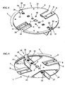
- Knife disk 1 shown is rotatably mounted with a central opening 2 on a non-illustrated drive shaft of a drive motor.
- Rotational drive can be provided more openings 3.
- the illustrated cutting disc has, relative to its axis of rotation 4 diametrically opposed radial slots 5, which are open to the periphery 6 of the blade disc 1.
- the trailing edge 8 of the radial slots 5 in the direction of rotation 7 has a blade receptacle 9, in which a chopper blade 10 is received and secured with a cutting edge 16.
- the blades 16 of the chopping blades determine a cutting plane 34 (FIG. Fig. 6 ).
- the cutter disk 1 also has two rupture blades 20, which lie in the circumferential direction 11 with a circumferential distance u to the respective chopper blade 10.
- the arrangement is advantageously made so that in each case a razor 20 precedes the chopper blade 10 in the direction of rotation 7.
- the razor 20 is located or its leading edge 25 is based on the chopper blade 10 approximately at its outer circle diameter;
- the tear gauge 20 is slightly in the circle diameter.
- Each razor 20 has a base body 21 (FIG. Fig. 4 ), which - like the FIGS. 2 and 3 show - may lie at an angle 22 to the axis of rotation 4.
- the doctor blade 20 is fixed with a radial mounting portion 23 on the bottom 12 of the cutter disk 1, wherein the mounting portion 23 extends approximately radially to the axis of rotation 4 and approximately parallel to the plane of the cutter disk 1.
- the mounting portion 23 of the tear blade 20 is fixed in an area on the underside 12 of the cutter disk 1, in which an additional sheet 14 fixed is.
- the additional sheet 14 has a circular-segment-shaped shape and extends approximately symmetrically between the radial slots 5, wherein the additional sheet 15 is fixed near the outer periphery 6 on the underside 12 of the cutter disk 1.
- Trained in the manner of a Fang toothing knife 20 extends at the attachment portion 23 from the bottom 12 of the blade disc 1 through a recess 15 in the peripheral edge 6 of the blade disc 1 through the top 13 of the blade out ( Fig. 2, 3rd ), wherein the roof edge 24 of the tearing knife 20 protrude beyond the cutting plane 34 defined by the cutters 16 of the chopping knives 10.
- the additional sheet 14 is preferably a sound-absorbing sheet, which is fastened in sandwich construction on the cutter disk 1.
- each tear blade 20 is aligned approximately in the circumferential direction 11 of the cutter disk 1, wherein the leading edge 7 in the direction of rotation 7 is formed as a front cutting edge of the cutting blade 20.
- the aligned in the circumferential direction 11 roof edge 24 of the main body 21 of the tear blade 20 may be formed as a roof cutting that projects beyond the cutting plane of the chopper 10. It may be expedient to form the trailing edge of the main body 21 as a cutting edge.
- the cutter disk 1 has a sawtooth-like outer diameter 6, that is, on the outer circumference 6 at least one or more height jumps a are formed.
- the height jump a is in the embodiment in each case in the range of a chopper blade 10 and a tear blade 20 and is preferably created by differently long radial edges of a blade associated radial slot 5 and the recess 15.
- the leading edge in the direction of rotation of the radial slot 5 or the recess 15 is shorter than the trailing longitudinal edge 8 of the radial slot 5 or the trailing longitudinal edge 18 of the open to the outer periphery 6 recess 15.
- a Räumeriel 17 is arranged, which - like the Fig. 2, 3rd and 5 show - approximately at right angles from the bottom 12 of the knife disc 1 protrudes and is provided for removal of the clippings from the knife chamber 28.
- the Räumeriel 17 extends over substantially the entire length of the mounting portion 23 at the trailing longitudinal edge 19 and forms together with the mounting portion 23 and the rupture knife 20 is a common, preferably a one-piece component.
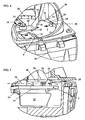
- the chopper blade 10 and the razor 20 each have a stop 30 or 31 associated with which cooperates with the respective blade 10, 20, and on a housing fixed Component 26 is provided. As the 6 and 7 show, the chopping blade 10 associated stop 31 extends approximately at the height of the cutting plane 34 above the top 13 of the cutter disk. 1
- the breaker blade 20 associated housing fixed stop 31 is located in the peripheral region of the cutter disk 1 also above the top 13 and interacts with the leading edge formed as a leading edge 25 cutting. It may be expedient to provide a further stop 32 associated with the breaking knife 20, which extends from the upright stop 31 above the cutter disk 1 in the circumferential direction to a portion which lies outside the outer circumference of the cutter disk 1. This stop 32 can advantageously interact with the cutting edge formed as a roof edge 24 cutting.
- the stops 30, 31 and 32 are formed on a common component 26 which is part of a hopper to the knife chamber 28.
- the housing-fixed component 26 is positively connected to the housing pot 29 of the knife chamber 28, so that the forces acting on the stops 30, 31 during cutting are absorbed by the housing pot 29 of the knife chamber 28.
- the hopper 27 thus forms a force-transmitting connected to the housing pot 29 component.
- FIG. 6 shows, with the central attachment 33 of the knife disc 1 on a drive shaft, a central rupture knife 40 to be set, the blade ends 41 are provided inclined obliquely outwards at an angle.
- the central razor 40 is rotatably supported by rotation stops 42 of the cutter disk 1 on the top 13 thereof.
- the knife ends 41 can advantageously protrude into the cutting area of the chopper blade 10.
Landscapes
- Life Sciences & Earth Sciences (AREA)
- Engineering & Computer Science (AREA)
- Food Science & Technology (AREA)
- Biodiversity & Conservation Biology (AREA)
- Ecology (AREA)
- Forests & Forestry (AREA)
- Environmental Sciences (AREA)
- Crushing And Pulverization Processes (AREA)
- Food-Manufacturing Devices (AREA)
- Dental Tools And Instruments Or Auxiliary Dental Instruments (AREA)
Description
- Die Erfindung betrifft einen Häcksler zum Zerkleinern von organischem Material, insbesondere Gartenhäcksler für Astwerk, Gestrüpp oder dgl. nach dem Oberbegriff des Anspruchs 1.
- Derartige Häcksler sind allgemein bekannt (siehe z.B.
US-A-3 674 220 ). Auf einer rotierenden Messerscheibe ist mindestens ein Häckselmesser befestigt, das eine sich etwa in Radialrichtung erstreckende Schneide aufweist und mit einem gehäusefesten Anschlag zusammenwirkt, um in die Messerkammer eingeführtes Material zu zerkleinern. Dabei soll der Häcksler sowohl kleine Äste, Gestrüpp, größere Äste und ähnliches derart zerkleinern, daß das Schnittgut einfach kompostiert werden kann. Dies setzt eine ausreichend feine Zerkleinerung des Schnittgutes voraus. - Der Erfindung liegt die Aufgabe zugrunde, einen gattungsgemäßen Häcksler derart weiterzubilden, daß unabhängig von dem in die Messerkammer eingeschobenen Material eine gleichmäßige, feine Zerkleinerung gewährleistet ist.
- Die Aufgabe wird erfindungsgemäß nach den kennzeichnenden Merkmalen des Anspruchs 1 gelöst.
- Das im Bereich des Außenumfangs der Messerscheibe angeordnete Reißmesser bewirkt einen Materialschnitt in Drehrichtung der drehenden Messerscheibe, so daß das Schnittgut ca. senkrecht zum Schnitt des nachfolgenden Häckselmessers geschnitten wird. Dadurch ist eine ausreichend feine Zerkleinerung sowohl gestrüppartigen Schnittgutes als auch von feinem und grobem Astwerk und anderem möglich.
- Vorteilhaft liegt das Reißmesser in Umfangsrichtung der Messerscheibe ausgerichtet, wobei an der vorlaufenden Kante des Reißmessers eine Frontschneide ausgebildet ist. Zweckmäßig ist ergänzend an der sich in Umfangsrichtung erstreckenden Dachkante des Reißmessers eine Dachschneide ausgebildet, so daß eine gute Zerschnitzelung des Materials gegeben ist.
- Das Reißmesser erstreckt sich über die Schnittebene der Häckselmesser hinaus, so daß der Schnitt des Reißmessers tiefer geht als die Schnittebene des Häckselmessers, wodurch ein sauberes Abtrennen eines einzelnen Hackschnitzels von dem zu zerkleinernden Gut gewährleistet ist.
- Dem Reißmesser ist - wie dem Häckselmesser - ein gehäusefester Anschlag zugeordnet, mit dem das Messer zusammenwirkt. Der dem Häckselmesser zugeordnete Anschlag und der dem Reißmesser zugeordnete Anschlag sind bevorzugt an einem gemeinsamen Bauteil ausgebildet, wobei das Bauteil vorzugsweise Teil eines Einfülltrichters zur Messerkammer ist.
- Weitere Merkmale der Erfindung ergeben sich aus den weiteren Ansprüchen, der Beschreibung und der Zeichnung, in der ein nachfolgend im Einzelnen beschriebenes Ausführungsbeispiel der Erfindung dargestellt ist. Es zeigen:
- Fig. 1
- eine Draufsicht auf eine erfindungsgemäße Messerscheibe von unten,
- Fig. 2
- einen Schnitt längs der Linie II-II in
Fig. 1 , - Fig. 3
- eine Seitenansicht der Messerscheibe nach
Fig. 1 , - Fig. 4
- eine perspektivische Ansicht der Messerscheibe nach
Fig. 1 von oben, - Fig. 5
- eine perspektivische Ansicht der erfindungsgemäßen Messerscheibe von unten,
- Fig. 6
- eine Teildarstellung einer Messerkammer mit darin angeordneter Messerscheibe nach
Fig. 1 , - Fig. 7
- einen Teilschnitt durch eine Messerkammer nach
Fig. 6 . - Die in den
Fig. 1 bis 5 gezeigte Messerscheibe 1 wird mit einer zentralen Öffnung 2 auf eine nicht näher dargestellte Antriebswelle eines Antriebsmotors drehfest aufgesetzt. Zur Drehmitnahme können weitere Öffnungen 3 vorgesehen sein. Die dargestellte Messerscheibe hat bezogen auf ihre Drehachse 4 einander diametral gegenüberliegende Radialschlitze 5, die zum Umfang 6 der Messerscheibe 1 offen sind. Die in Drehrichtung 7 nachlaufende Kante 8 der Radialschlitze 5 weist eine Messeraufnahme 9 auf, in der ein Häckselmesser 10 mit einer Schneide 16 aufgenommen und befestigt ist. Die Schneiden 16 der Häckselmesser bestimmen eine Schnittebene 34 (Fig. 6 ). - Die Messerscheibe 1 weist ferner zwei Reißmesser 20 auf, die in Umfangsrichtung 11 mit einem Umfangsabstand u zum jeweiligen Häckselmesser 10 liegen. Die Anordnung ist vorteilhaft so getroffen, daß in Drehrichtung 7 jeweils ein Reißmesser 20 dem Häckselmesser 10 vorläuft. Das Reißmesser 20 liegt bzw. dessen vorlaufende Kante 25 liegt bezogen auf das Häckselmesser 10 etwa an dessen äußeren Flugkreisdurchmesser; vorteilhaft liegt das Reißmessers 20 geringfügig in dem Flugkreisdurchmesser.
- Jedes Reißmesser 20 hat einen Grundkörper 21 (
Fig. 4 ), der - wie dieFig. 2 und 3 zeigen - unter einem Winkel 22 zur Drehachse 4 liegen kann. Das Reißmesser 20 ist mit einem radialen Befestigungsabschnitt 23 auf der Unterseite 12 der Messerscheibe 1 festgelegt, wobei sich der Befestigungsabschnitt 23 etwa radial zur Drehachse 4 und etwa parallel zur Ebene der Messerscheibe 1 erstreckt. Wie dieFig. 1, 2 und5 zeigen, ist der Befestigungsabschnitt 23 des Reißmessers 20 in einem Bereich auf der Unterseite 12 der Messerscheibe 1 befestigt, in der ein Zusatzblech 14 festgelegt ist. Das Zusatzblech 14 hat eine kreissegmentförmige Form und erstreckt sich etwa symmetrisch zwischen den Radialschlitzen 5, wobei das Zusatzblech 15 nahe dem Außenumfang 6 auf der Unterseite 12 der Messerscheibe 1 festgelegt ist. - Das nach Art eines Reißzahns ausgebildete Reißmesser 20 erstreckt sich am Befestigungsabschnitt 23 von der Unterseite 12 der Messerscheibe 1 durch eine Ausnehmung 15 im Umfangsrand 6 der Messerscheibe 1 hindurch über die Oberseite 13 der Messerscheibe hinaus (
Fig. 2, 3 ), wobei die Dachkante 24 des Reißmessers 20 über die durch die Schneiden 16 der Häckselmesser 10 bestimmte Schnittebene 34 hinausragen. Das Zusatzblech 14 ist dabei bevorzugt ein geräuschdämmendes Blech, welches in Sandwichbauweise auf der Messerscheibe 1 befestigt ist. - Der Grundkörper 21 jedes Reißmessers 20 liegt etwa in Umfangsrichtung 11 der Messerscheibe 1 ausgerichtet, wobei die in Drehrichtung 7 vorlaufende Kante 25 als Frontschneide des Reißmessers 20 ausgebildet ist. Die in Umfangsrichtung 11 ausgerichtet liegende Dachkante 24 des Grundkörpers 21 des Reißmessers 20 kann als Dachschneide ausgebildet sein, die über die Schnittebene der Häckselmesser 10 übersteht. Es kann zweckmäßig sein, auch die nachlaufende Kante des Grundkörpers 21 als Schneide auszubilden.
- Wie
Fig. 1 zeigt, hat die Messerscheibe 1 einen sägezahnähnlichen Außendurchmesser 6, d.h. am Außenumfang 6 ist mindestens ein oder sind mehrere Höhensprünge a ausgebildet. Der Höhensprung a liegt im Ausführungsbeispiel jeweils im Bereich eines Häckselmessers 10 bzw. eines Reißmessers 20 und ist vorzugsweise durch unterschiedlich lange Radialkanten des einem Messer zugeordneten Radialschlitzes 5 bzw. der Ausnehmung 15 geschaffen. So ist die in Drehrichtung vorlaufende Kante des Radialschlitzes 5 bzw. der Ausnehmung 15 um den Höhensprung a kürzer ausgebildet als die nachlaufende Längskante 8 des Radialschlitzes 5 bzw. die nachlaufende Längskante 18 der zum Außenumfang 6 offenen Ausnehmung 15. Durch diesen geschaffenen Freiwinkel wird gewährleistet, daß Häckselgut, welches sich im Betrieb zwischen dem Außenumfang 6 der Messerscheibe 1 und der Messerkammerinnenwand klemmen kann, bis zur nächsten Kante bzw. bis zum folgenden Messer freigestellt wird. - Am Befestigungsabschnitt 23 des Reißmessers 20 ist ein Räumflügel 17 angeordnet, der - wie die
Fig. 2, 3 und5 zeigen - etwa rechtwinklig von der Unterseite 12 der Messerscheibe 1 absteht und zur Abförderung des Schnittgutes aus der Messerkammer 28 vorgesehen ist. Der Räumflügel 17 erstreckt sich über im wesentlichen die gesamte Länge des Befestigungsabschnittes 23 an dessen nachlaufender Längskante 19 und bildet zusammen mit dem Befestigungsabschnitt 23 und dem Reißmesser 20 ein gemeinsames, vorzugsweise ein einteiliges Bauteil. - Dem Häckselmesser 10 sowie dem Reißmesser 20 ist jeweils ein Anschlag 30 bzw. 31 zugeordnet, der mit dem jeweiligen Messer 10, 20 zusammenwirkt, und an einem gehäusefesten Bauteil 26 vorgesehen ist. Wie die
Fig. 6 und 7 zeigen, erstreckt sich der dem Häckselmesser 10 zugeordnete Anschlag 31 etwa auf der Höhe der Schnittebene 34 oberhalb der Oberseite 13 der Messerscheibe 1. - Der dem Reißmesser 20 zugeordnete gehäusefeste Anschlag 31 liegt im Umfangsbereich der Messerscheibe 1 ebenfalls oberhalb der Oberseite 13 und wirkt mit der als Frontschneide ausgebildeten vorlaufenden Kante 25 schneidend zusammen. Es kann zweckmäßig sein, einen weiteren dem Reißmesser 20 zugeordneten Anschlag 32 vorzusehen, der sich von dem aufrechten Anschlag 31 oberhalb der Messerscheibe 1 in Umfangsrichtung bis in einen Abschnitt erstreckt, der außerhalb des Außenumfangs der Messerscheibe 1 liegt. Dieser Anschlag 32 kann vorteilhaft mit der als Dachschneide ausgebildeten Dachkante 24 schneidend zusammenwirken.
- Die Anschläge 30, 31 und 32 sind an einem gemeinsamen Bauteil 26 ausgebildet, welches Teil eines Einfülltrichters zur Messerkammer 28 ist. Das gehäusefeste Bauteil 26 ist formschlüssig mit dem Gehäusetopf 29 der Messerkammer 28 verbunden, so daß die beim Schnitt auf die Anschläge 30, 31 wirkenden Kräfte vom Gehäusetopf 29 der Messerkammer 28 aufgenommen sind. Der Einfülltrichter 27 bildet so ein mit dem Gehäusetopf 29 kraftübertragend verbundenes Bauteil.
- Wie
Fig. 6 zeigt, kann mit der zentralen Befestigung 33 der Messerscheibe 1 auf einer Antriebswelle ein zentrales Reißmesser 40 festgelegt sein, dessen Messerenden 41 schräg nach außen unter einem Winkel angestellt vorgesehen sind. - Das zentrale Reißmesser 40 ist durch Drehanschläge 42 der Messerscheibe 1 drehfest auf deren Oberseite 13 gehalten. Die Messerenden 41 können vorteilhaft bis in den Schnittbereich der Häckselmesser 10 ragen.
Claims (16)
- Häcksler zum Zerkleinern von organischem Material, insbesondere Gartenhäcksler für Astwerk, Gestrüpp oder dgl., bestehend aus einer Messerkammer (28) mit einer rotierenden Messerscheibe (1), auf der mindestens ein Häckselmesser (10) befestigt ist, und das Häckselmesser (10) eine sich etwa in Radialrichtung erstreckende Schneide (16) aufweist, wobei das Häckselmesser (10) zum Zerkleinern des Materials mit einem gehäusefesten Anschlag (30) zusammenwirkt,
dadurch gekennzeichnet, daß im Bereich des Außenumfangs (6) der Messerscheibe (1) ein Reißmesser (20) angeordnet ist, das nach Art eines Reißzahns ausgebildet ist und das in Umfangsrichtung (11) der Messerscheibe (1) mit Abstand (u) zum Häckselmesser liegt. - Häcksler nach Anspruch 1,
dadurch gekennzeichnet, daß der Grundkörper (21) des Reißmessers (20) in Umfangsrichtung (11) der Messerscheibe (1) ausgerichtet liegt. - Häcksler nach Anspruch 1 oder 2,
dadurch gekennzeichnet, daß an einer vorlaufenden Kante (25) des Grundkörpers (21) des Reißmessers (20) eine Frontschneide ausgebildet ist. - Häcksler nach einem der Ansprüche 1 bis 3,
dadurch gekennzeichnet, daß an einer in Umfangsrichtung (11) sich erstreckenden Dachkante (24) des Grundkörpers (21) des Reißmessers (20) eine Dachschneide ausgebildet ist. - Häcksler nach einem der Ansprüche 1 bis 4,
dadurch gekennzeichnet, daß das Reißmesser (20) über die Schnittebene (34) des Häckselmessers (10) übersteht. - Häcksler nach einem der Ansprüche 1 bis 5,
dadurch gekennzeichnet, daß das Reißmesser (10) in einer Umfangsausnehmung (15) der Messerscheibe (1) liegt. - Häcksler nach einem der Ansprüche 1 bis 6,
dadurch gekennzeichnet, daß sich das Reißmesser (20) von der Unterseite (12) der Messerscheibe (1) über dessen Oberseite (13) hinaus erstreckt. - Häcksler nach einem der Ansprüche 1 bis 7,
dadurch gekennzeichnet, daß das Reißmesser (20) mit einem sich etwa parallel zur Messerscheibe (1) erstreckenden Befestigungsabschnitt (23) an der Messerscheibe (1) festgelegt ist. - Häcksler nach Anspruch 8,
dadurch gekennzeichnet, daß sich der Befestigungsabschnitt (23) etwa radial zur Messerscheibe (1) erstreckt. - Häcksler nach einem der Ansprüche 1 bis 9,
dadurch gekennzeichnet, daß das Reißmesser (20) in einem Bereich der Messerscheibe (1) befestigt ist, in dem die Messerscheibe (1) ein Zusatzblech (15) trägt. - Häcksler nach Anspruch 10,
dadurch gekennzeichnet, daß das Zusatzblech (14) ein geräuschdämmendes Blech ist. - Häcksler nach einem der Ansprüche 1 bis 11,
dadurch gekennzeichnet, daß dem Reißmesser (20) ein gehäusefester Anschlag (31, 32) zugeordnet ist. - Häcksler nach Anspruch 12,
dadurch gekennzeichnet, daß der dem Häckselmesser (10) zugeordnete Anschlag (30) und der dem Reißmesser (20) zugeordnete Anschlag (31, 32) an einem gemeinsamen Bauteil (26) der Messerkammer (28) ausgebildet sind. - Häcksler nach Anspruch 13,
dadurch gekennzeichnet, daß das Bauteil (26) Teil eines Einfülltrichters (27) zur Messerkammer (28) ist. - Häcksler nach Anspruch 8 oder 9,
dadurch gekennzeichnet, daß das Reißmesser (20), sein Befestigungsabschnitt (23) und ein Räumflügel (17) ein gemeinsames Bauteil bilden. - Häcksler nach Anspruch 15,
dadurch gekennzeichnet, daß der Reißzahn (20), sein Befestigungsabschnitt (23) und ein Räumflügel (17) ein einteiliges Bauteil bilden.
Applications Claiming Priority (2)
| Application Number | Priority Date | Filing Date | Title |
|---|---|---|---|
| DE20320044U DE20320044U1 (de) | 2003-12-24 | 2003-12-24 | Messerscheibe mit Reißzähnen für einen Häcksler |
| DE20320044U | 2003-12-24 |
Publications (2)
| Publication Number | Publication Date |
|---|---|
| EP1547459A1 EP1547459A1 (de) | 2005-06-29 |
| EP1547459B1 true EP1547459B1 (de) | 2009-05-27 |
Family
ID=31984906
Family Applications (1)
| Application Number | Title | Priority Date | Filing Date |
|---|---|---|---|
| EP04029936A Expired - Lifetime EP1547459B1 (de) | 2003-12-24 | 2004-12-17 | Messerscheibe mit Reisszähnen für einen Häcksler |
Country Status (4)
| Country | Link |
|---|---|
| EP (1) | EP1547459B1 (de) |
| AT (1) | ATE432004T1 (de) |
| DE (2) | DE20320044U1 (de) |
| ES (1) | ES2326476T3 (de) |
Families Citing this family (6)
| Publication number | Priority date | Publication date | Assignee | Title |
|---|---|---|---|---|
| FR2948582B1 (fr) * | 2009-07-31 | 2011-08-19 | Kiva | Dispositif de broyage des vegetaux. |
| EP2564930B1 (de) * | 2011-08-30 | 2013-12-18 | Viking GmbH | Häcksler |
| AT516805B1 (de) * | 2015-02-02 | 2016-11-15 | Kesla Oyj | Gebläse einer Hackmaschine |
| CN107442224B (zh) * | 2016-05-30 | 2024-09-06 | 珠海格力电器股份有限公司 | 研磨盘结构及食物垃圾处理器 |
| CN111450958B (zh) * | 2019-01-21 | 2025-03-11 | 上海盛晟机械有限公司 | 一种破碎刀盘 |
| CN110787883B (zh) * | 2019-12-13 | 2024-02-13 | 西部新锆核材料科技有限公司 | 一种锆合金屑料破碎机破碎装置 |
Family Cites Families (4)
| Publication number | Priority date | Publication date | Assignee | Title |
|---|---|---|---|---|
| US3674220A (en) * | 1970-12-07 | 1972-07-04 | Omark Industries Inc | Chipper shredder |
| DE2934792C2 (de) * | 1979-08-29 | 1981-12-03 | Crones & Co oHG, Kaltpreßwerk Ansbach, 8800 Ansbach | Motorisch angetriebenes Zerkleinerungsgerät für Abfälle, insbesondere Gartenabfälle. |
| DE3722339A1 (de) * | 1987-07-07 | 1989-01-19 | Crones & Co Gmbh | Motorisch angetriebener gartenabfallhaecksler |
| ATE114402T1 (de) * | 1989-09-02 | 1994-12-15 | Sabo Maschf | Häcksler zum zerkleinern von gartenabfällen mit einem schneidwerk. |
-
2003
- 2003-12-24 DE DE20320044U patent/DE20320044U1/de not_active Expired - Lifetime
-
2004
- 2004-12-17 DE DE502004009523T patent/DE502004009523D1/de not_active Expired - Lifetime
- 2004-12-17 ES ES04029936T patent/ES2326476T3/es not_active Expired - Lifetime
- 2004-12-17 AT AT04029936T patent/ATE432004T1/de active
- 2004-12-17 EP EP04029936A patent/EP1547459B1/de not_active Expired - Lifetime
Also Published As
| Publication number | Publication date |
|---|---|
| ATE432004T1 (de) | 2009-06-15 |
| DE502004009523D1 (de) | 2009-07-09 |
| DE20320044U1 (de) | 2004-03-04 |
| EP1547459A1 (de) | 2005-06-29 |
| ES2326476T3 (es) | 2009-10-13 |
Similar Documents
| Publication | Publication Date | Title |
|---|---|---|
| EP0416315B1 (de) | Häcksler zum Zerkleinern von Gartenabfällen mit einem Schneidwerk | |
| DE102019108306A1 (de) | Schneidmühle zum schneidenden Zerkleinern von Proben | |
| DE2158778A1 (de) | Zerkleinerungsvorrichtung fur Holz und Laub und dergleichen Materialien | |
| DE3221431A1 (de) | Vorrichtung zum zerkleinern von kunststoffteilen, insbesondere angussstuecken | |
| EP1547459B1 (de) | Messerscheibe mit Reisszähnen für einen Häcksler | |
| EP0124138B1 (de) | Verfahren und Vorrichtung zur Zerkleinerung von Pflanzengut | |
| DE2256267B2 (de) | Mit Scherwirkung arbeitender Zerkleinerer | |
| DE102008039258A1 (de) | Zerkleinerungsmaschine | |
| DE4328506C1 (de) | Spänebrecher | |
| EP2394743A1 (de) | Zerkleinerungsmaschine | |
| EP0598306B1 (de) | Häcksler, insbesondere für Haus- und Gartenabfälle | |
| EP2564930B1 (de) | Häcksler | |
| EP0505701B1 (de) | Gartenhäcksler mit Messergehäuse und darin umlaufend anzutreibenden Flachmessern | |
| EP0630686B1 (de) | Gartenabfallzerkleinerer | |
| EP0505702B1 (de) | Gartenhäcksler mit Messergehäuse und darin umlaufend anzutreibenden Flach- sowie Vorzerkleinerungsmessern | |
| DE4427700C2 (de) | Vorrichtung zum Häckseln von Gartenabfällen | |
| EP0089571B1 (de) | Vorrichtung zum Zerkleinern von Schwachholz | |
| AT404435B (de) | Schneidwerk für gartenhäcksler | |
| EP0712663A1 (de) | Metallspänezerkleinerer | |
| EP1782680B1 (de) | Vorrichtung zum Zerkleinern von Pflanzengut in Form von Grünmasse und/oder Schwachholz | |
| EP2014371B1 (de) | Häcksler | |
| DE29611773U1 (de) | Häcksler | |
| DE2424725C3 (de) | Zerkleinerungsmaschine für sperriges Gut | |
| EP1967272B1 (de) | Häcksler | |
| EP0688605B1 (de) | Messeranordnung für eine Maschine zum Zerkleinern von pflanzlichen Abfällen |
Legal Events
| Date | Code | Title | Description |
|---|---|---|---|
| PUAI | Public reference made under article 153(3) epc to a published international application that has entered the european phase |
Free format text: ORIGINAL CODE: 0009012 |
|
| AK | Designated contracting states |
Kind code of ref document: A1 Designated state(s): AT BE BG CH CY CZ DE DK EE ES FI FR GB GR HU IE IS IT LI LT LU MC NL PL PT RO SE SI SK TR |
|
| AX | Request for extension of the european patent |
Extension state: AL BA HR LV MK YU |
|
| 17P | Request for examination filed |
Effective date: 20050621 |
|
| AKX | Designation fees paid |
Designated state(s): AT BE BG CH CY CZ DE DK EE ES FI FR GB GR HU IE IS IT LI LT LU MC NL PL PT RO SE SI SK TR |
|
| GRAP | Despatch of communication of intention to grant a patent |
Free format text: ORIGINAL CODE: EPIDOSNIGR1 |
|
| GRAS | Grant fee paid |
Free format text: ORIGINAL CODE: EPIDOSNIGR3 |
|
| GRAA | (expected) grant |
Free format text: ORIGINAL CODE: 0009210 |
|
| AK | Designated contracting states |
Kind code of ref document: B1 Designated state(s): AT BE BG CH CY CZ DE DK EE ES FI FR GB GR HU IE IS IT LI LT LU MC NL PL PT RO SE SI SK TR |
|
| REG | Reference to a national code |
Ref country code: GB Ref legal event code: FG4D Free format text: NOT ENGLISH |
|
| REG | Reference to a national code |
Ref country code: CH Ref legal event code: EP |
|
| REG | Reference to a national code |
Ref country code: IE Ref legal event code: FG4D Free format text: LANGUAGE OF EP DOCUMENT: GERMAN |
|
| REF | Corresponds to: |
Ref document number: 502004009523 Country of ref document: DE Date of ref document: 20090709 Kind code of ref document: P |
|
| REG | Reference to a national code |
Ref country code: ES Ref legal event code: FG2A Ref document number: 2326476 Country of ref document: ES Kind code of ref document: T3 |
|
| PG25 | Lapsed in a contracting state [announced via postgrant information from national office to epo] |
Ref country code: LT Free format text: LAPSE BECAUSE OF FAILURE TO SUBMIT A TRANSLATION OF THE DESCRIPTION OR TO PAY THE FEE WITHIN THE PRESCRIBED TIME-LIMIT Effective date: 20090527 Ref country code: FI Free format text: LAPSE BECAUSE OF FAILURE TO SUBMIT A TRANSLATION OF THE DESCRIPTION OR TO PAY THE FEE WITHIN THE PRESCRIBED TIME-LIMIT Effective date: 20090527 Ref country code: PT Free format text: LAPSE BECAUSE OF FAILURE TO SUBMIT A TRANSLATION OF THE DESCRIPTION OR TO PAY THE FEE WITHIN THE PRESCRIBED TIME-LIMIT Effective date: 20090927 |
|
| NLV1 | Nl: lapsed or annulled due to failure to fulfill the requirements of art. 29p and 29m of the patents act | ||
| PG25 | Lapsed in a contracting state [announced via postgrant information from national office to epo] |
Ref country code: IS Free format text: LAPSE BECAUSE OF FAILURE TO SUBMIT A TRANSLATION OF THE DESCRIPTION OR TO PAY THE FEE WITHIN THE PRESCRIBED TIME-LIMIT Effective date: 20090927 Ref country code: NL Free format text: LAPSE BECAUSE OF FAILURE TO SUBMIT A TRANSLATION OF THE DESCRIPTION OR TO PAY THE FEE WITHIN THE PRESCRIBED TIME-LIMIT Effective date: 20090527 Ref country code: SI Free format text: LAPSE BECAUSE OF FAILURE TO SUBMIT A TRANSLATION OF THE DESCRIPTION OR TO PAY THE FEE WITHIN THE PRESCRIBED TIME-LIMIT Effective date: 20090527 Ref country code: SE Free format text: LAPSE BECAUSE OF FAILURE TO SUBMIT A TRANSLATION OF THE DESCRIPTION OR TO PAY THE FEE WITHIN THE PRESCRIBED TIME-LIMIT Effective date: 20090827 Ref country code: PL Free format text: LAPSE BECAUSE OF FAILURE TO SUBMIT A TRANSLATION OF THE DESCRIPTION OR TO PAY THE FEE WITHIN THE PRESCRIBED TIME-LIMIT Effective date: 20090527 |
|
| REG | Reference to a national code |
Ref country code: IE Ref legal event code: FD4D |
|
| PG25 | Lapsed in a contracting state [announced via postgrant information from national office to epo] |
Ref country code: IE Free format text: LAPSE BECAUSE OF FAILURE TO SUBMIT A TRANSLATION OF THE DESCRIPTION OR TO PAY THE FEE WITHIN THE PRESCRIBED TIME-LIMIT Effective date: 20090527 Ref country code: EE Free format text: LAPSE BECAUSE OF FAILURE TO SUBMIT A TRANSLATION OF THE DESCRIPTION OR TO PAY THE FEE WITHIN THE PRESCRIBED TIME-LIMIT Effective date: 20090527 Ref country code: DK Free format text: LAPSE BECAUSE OF FAILURE TO SUBMIT A TRANSLATION OF THE DESCRIPTION OR TO PAY THE FEE WITHIN THE PRESCRIBED TIME-LIMIT Effective date: 20090527 Ref country code: RO Free format text: LAPSE BECAUSE OF FAILURE TO SUBMIT A TRANSLATION OF THE DESCRIPTION OR TO PAY THE FEE WITHIN THE PRESCRIBED TIME-LIMIT Effective date: 20090527 Ref country code: CZ Free format text: LAPSE BECAUSE OF FAILURE TO SUBMIT A TRANSLATION OF THE DESCRIPTION OR TO PAY THE FEE WITHIN THE PRESCRIBED TIME-LIMIT Effective date: 20090527 |
|
| PG25 | Lapsed in a contracting state [announced via postgrant information from national office to epo] |
Ref country code: SK Free format text: LAPSE BECAUSE OF FAILURE TO SUBMIT A TRANSLATION OF THE DESCRIPTION OR TO PAY THE FEE WITHIN THE PRESCRIBED TIME-LIMIT Effective date: 20090527 |
|
| PG25 | Lapsed in a contracting state [announced via postgrant information from national office to epo] |
Ref country code: BG Free format text: LAPSE BECAUSE OF FAILURE TO SUBMIT A TRANSLATION OF THE DESCRIPTION OR TO PAY THE FEE WITHIN THE PRESCRIBED TIME-LIMIT Effective date: 20090827 |
|
| PLBE | No opposition filed within time limit |
Free format text: ORIGINAL CODE: 0009261 |
|
| STAA | Information on the status of an ep patent application or granted ep patent |
Free format text: STATUS: NO OPPOSITION FILED WITHIN TIME LIMIT |
|
| 26N | No opposition filed |
Effective date: 20100302 |
|
| PG25 | Lapsed in a contracting state [announced via postgrant information from national office to epo] |
Ref country code: MC Free format text: LAPSE BECAUSE OF NON-PAYMENT OF DUE FEES Effective date: 20100701 |
|
| REG | Reference to a national code |
Ref country code: CH Ref legal event code: PL |
|
| PG25 | Lapsed in a contracting state [announced via postgrant information from national office to epo] |
Ref country code: GR Free format text: LAPSE BECAUSE OF FAILURE TO SUBMIT A TRANSLATION OF THE DESCRIPTION OR TO PAY THE FEE WITHIN THE PRESCRIBED TIME-LIMIT Effective date: 20090828 Ref country code: LI Free format text: LAPSE BECAUSE OF NON-PAYMENT OF DUE FEES Effective date: 20091231 Ref country code: CH Free format text: LAPSE BECAUSE OF NON-PAYMENT OF DUE FEES Effective date: 20091231 |
|
| PG25 | Lapsed in a contracting state [announced via postgrant information from national office to epo] |
Ref country code: IT Free format text: LAPSE BECAUSE OF FAILURE TO SUBMIT A TRANSLATION OF THE DESCRIPTION OR TO PAY THE FEE WITHIN THE PRESCRIBED TIME-LIMIT Effective date: 20090527 |
|
| PG25 | Lapsed in a contracting state [announced via postgrant information from national office to epo] |
Ref country code: LU Free format text: LAPSE BECAUSE OF NON-PAYMENT OF DUE FEES Effective date: 20091217 |
|
| PG25 | Lapsed in a contracting state [announced via postgrant information from national office to epo] |
Ref country code: HU Free format text: LAPSE BECAUSE OF FAILURE TO SUBMIT A TRANSLATION OF THE DESCRIPTION OR TO PAY THE FEE WITHIN THE PRESCRIBED TIME-LIMIT Effective date: 20091128 |
|
| PG25 | Lapsed in a contracting state [announced via postgrant information from national office to epo] |
Ref country code: TR Free format text: LAPSE BECAUSE OF FAILURE TO SUBMIT A TRANSLATION OF THE DESCRIPTION OR TO PAY THE FEE WITHIN THE PRESCRIBED TIME-LIMIT Effective date: 20090527 |
|
| PG25 | Lapsed in a contracting state [announced via postgrant information from national office to epo] |
Ref country code: CY Free format text: LAPSE BECAUSE OF FAILURE TO SUBMIT A TRANSLATION OF THE DESCRIPTION OR TO PAY THE FEE WITHIN THE PRESCRIBED TIME-LIMIT Effective date: 20090527 |
|
| REG | Reference to a national code |
Ref country code: FR Ref legal event code: PLFP Year of fee payment: 12 |
|
| REG | Reference to a national code |
Ref country code: FR Ref legal event code: PLFP Year of fee payment: 13 |
|
| REG | Reference to a national code |
Ref country code: FR Ref legal event code: PLFP Year of fee payment: 14 |
|
| REG | Reference to a national code |
Ref country code: DE Ref legal event code: R082 Ref document number: 502004009523 Country of ref document: DE Representative=s name: PATENTANWAELTE DIPL.-ING. W. JACKISCH & PARTNE, DE Ref country code: DE Ref legal event code: R082 Ref document number: 502004009523 Country of ref document: DE Representative=s name: PATENTANWAELTE DIPL.-ING. WALTER JACKISCH & PA, DE Ref country code: DE Ref legal event code: R081 Ref document number: 502004009523 Country of ref document: DE Owner name: ANDREAS STIHL AG & CO. KG, DE Free format text: FORMER OWNER: VIKING GMBH, LANGKAMPFEN, AT |
|
| REG | Reference to a national code |
Ref country code: ES Ref legal event code: PC2A Owner name: ANDREAS STIHL AG & CO. KG Effective date: 20181008 |
|
| REG | Reference to a national code |
Ref country code: GB Ref legal event code: 732E Free format text: REGISTERED BETWEEN 20180927 AND 20181005 |
|
| REG | Reference to a national code |
Ref country code: BE Ref legal event code: PD Owner name: ANDREAS STIHL AG & CO. KG; DE Free format text: DETAILS ASSIGNMENT: CHANGE OF OWNER(S), CESSION; FORMER OWNER NAME: VIKING GMBH Effective date: 20181009 |
|
| REG | Reference to a national code |
Ref country code: AT Ref legal event code: PC Ref document number: 432004 Country of ref document: AT Kind code of ref document: T Owner name: ANDREAS STIHL AG & CO. KG, DE Effective date: 20181203 |
|
| PGFP | Annual fee paid to national office [announced via postgrant information from national office to epo] |
Ref country code: GB Payment date: 20221220 Year of fee payment: 19 Ref country code: FR Payment date: 20221222 Year of fee payment: 19 Ref country code: AT Payment date: 20221221 Year of fee payment: 19 |
|
| PGFP | Annual fee paid to national office [announced via postgrant information from national office to epo] |
Ref country code: BE Payment date: 20221226 Year of fee payment: 19 |
|
| PGFP | Annual fee paid to national office [announced via postgrant information from national office to epo] |
Ref country code: ES Payment date: 20230118 Year of fee payment: 19 |
|
| PGFP | Annual fee paid to national office [announced via postgrant information from national office to epo] |
Ref country code: DE Payment date: 20221227 Year of fee payment: 19 |
|
| REG | Reference to a national code |
Ref country code: DE Ref legal event code: R119 Ref document number: 502004009523 Country of ref document: DE |
|
| REG | Reference to a national code |
Ref country code: AT Ref legal event code: MM01 Ref document number: 432004 Country of ref document: AT Kind code of ref document: T Effective date: 20231217 |
|
| GBPC | Gb: european patent ceased through non-payment of renewal fee |
Effective date: 20231217 |
|
| REG | Reference to a national code |
Ref country code: BE Ref legal event code: MM Effective date: 20231231 |
|
| PG25 | Lapsed in a contracting state [announced via postgrant information from national office to epo] |
Ref country code: DE Free format text: LAPSE BECAUSE OF NON-PAYMENT OF DUE FEES Effective date: 20240702 |
|
| PG25 | Lapsed in a contracting state [announced via postgrant information from national office to epo] |
Ref country code: GB Free format text: LAPSE BECAUSE OF NON-PAYMENT OF DUE FEES Effective date: 20231217 |
|
| PG25 | Lapsed in a contracting state [announced via postgrant information from national office to epo] |
Ref country code: BE Free format text: LAPSE BECAUSE OF NON-PAYMENT OF DUE FEES Effective date: 20231231 |
|
| PG25 | Lapsed in a contracting state [announced via postgrant information from national office to epo] |
Ref country code: FR Free format text: LAPSE BECAUSE OF NON-PAYMENT OF DUE FEES Effective date: 20231231 |
|
| PG25 | Lapsed in a contracting state [announced via postgrant information from national office to epo] |
Ref country code: AT Free format text: LAPSE BECAUSE OF NON-PAYMENT OF DUE FEES Effective date: 20231217 |
|
| PG25 | Lapsed in a contracting state [announced via postgrant information from national office to epo] |
Ref country code: GB Free format text: LAPSE BECAUSE OF NON-PAYMENT OF DUE FEES Effective date: 20231217 Ref country code: FR Free format text: LAPSE BECAUSE OF NON-PAYMENT OF DUE FEES Effective date: 20231231 Ref country code: DE Free format text: LAPSE BECAUSE OF NON-PAYMENT OF DUE FEES Effective date: 20240702 Ref country code: BE Free format text: LAPSE BECAUSE OF NON-PAYMENT OF DUE FEES Effective date: 20231231 Ref country code: AT Free format text: LAPSE BECAUSE OF NON-PAYMENT OF DUE FEES Effective date: 20231217 |
|
| REG | Reference to a national code |
Ref country code: ES Ref legal event code: FD2A Effective date: 20250131 |
|
| PG25 | Lapsed in a contracting state [announced via postgrant information from national office to epo] |
Ref country code: ES Free format text: LAPSE BECAUSE OF NON-PAYMENT OF DUE FEES Effective date: 20231218 |