EP1547278B1 - Signal-, störungs- und rauschleistungsmessung - Google Patents
Signal-, störungs- und rauschleistungsmessung Download PDFInfo
- Publication number
- EP1547278B1 EP1547278B1 EP03794510A EP03794510A EP1547278B1 EP 1547278 B1 EP1547278 B1 EP 1547278B1 EP 03794510 A EP03794510 A EP 03794510A EP 03794510 A EP03794510 A EP 03794510A EP 1547278 B1 EP1547278 B1 EP 1547278B1
- Authority
- EP
- European Patent Office
- Prior art keywords
- signal
- interference
- power
- noise
- primary
- Prior art date
- Legal status (The legal status is an assumption and is not a legal conclusion. Google has not performed a legal analysis and makes no representation as to the accuracy of the status listed.)
- Expired - Lifetime
Links
Images


Classifications
-
- H—ELECTRICITY
- H04—ELECTRIC COMMUNICATION TECHNIQUE
- H04B—TRANSMISSION
- H04B7/00—Radio transmission systems, i.e. using radiation field
- H04B7/14—Relay systems
- H04B7/15—Active relay systems
- H04B7/185—Space-based or airborne stations; Stations for satellite systems
- H04B7/1851—Systems using a satellite or space-based relay
- H04B7/18515—Transmission equipment in satellites or space-based relays
-
- H—ELECTRICITY
- H04—ELECTRIC COMMUNICATION TECHNIQUE
- H04B—TRANSMISSION
- H04B17/00—Monitoring; Testing
- H04B17/30—Monitoring; Testing of propagation channels
- H04B17/309—Measuring or estimating channel quality parameters
- H04B17/318—Received signal strength
-
- H—ELECTRICITY
- H04—ELECTRIC COMMUNICATION TECHNIQUE
- H04B—TRANSMISSION
- H04B7/00—Radio transmission systems, i.e. using radiation field
- H04B7/14—Relay systems
- H04B7/15—Active relay systems
- H04B7/185—Space-based or airborne stations; Stations for satellite systems
- H04B7/1851—Systems using a satellite or space-based relay
-
- H—ELECTRICITY
- H04—ELECTRIC COMMUNICATION TECHNIQUE
- H04B—TRANSMISSION
- H04B7/00—Radio transmission systems, i.e. using radiation field
- H04B7/14—Relay systems
- H04B7/15—Active relay systems
- H04B7/185—Space-based or airborne stations; Stations for satellite systems
- H04B7/18523—Satellite systems for providing broadcast service to terrestrial stations, i.e. broadcast satellite service
- H04B7/18526—Arrangements for data linking, networking or transporting, or for controlling an end to end session
-
- H—ELECTRICITY
- H04—ELECTRIC COMMUNICATION TECHNIQUE
- H04L—TRANSMISSION OF DIGITAL INFORMATION, e.g. TELEGRAPHIC COMMUNICATION
- H04L1/00—Arrangements for detecting or preventing errors in the information received
- H04L1/20—Arrangements for detecting or preventing errors in the information received using signal quality detector
-
- H—ELECTRICITY
- H04—ELECTRIC COMMUNICATION TECHNIQUE
- H04L—TRANSMISSION OF DIGITAL INFORMATION, e.g. TELEGRAPHIC COMMUNICATION
- H04L1/00—Arrangements for detecting or preventing errors in the information received
- H04L1/20—Arrangements for detecting or preventing errors in the information received using signal quality detector
- H04L1/206—Arrangements for detecting or preventing errors in the information received using signal quality detector for modulated signals
-
- H—ELECTRICITY
- H04—ELECTRIC COMMUNICATION TECHNIQUE
- H04L—TRANSMISSION OF DIGITAL INFORMATION, e.g. TELEGRAPHIC COMMUNICATION
- H04L1/00—Arrangements for detecting or preventing errors in the information received
- H04L1/20—Arrangements for detecting or preventing errors in the information received using signal quality detector
- H04L1/208—Arrangements for detecting or preventing errors in the information received using signal quality detector involving signal re-encoding
-
- H—ELECTRICITY
- H04—ELECTRIC COMMUNICATION TECHNIQUE
- H04L—TRANSMISSION OF DIGITAL INFORMATION, e.g. TELEGRAPHIC COMMUNICATION
- H04L27/00—Modulated-carrier systems
- H04L27/18—Phase-modulated carrier systems, i.e. using phase-shift keying
- H04L27/183—Multiresolution systems
-
- H—ELECTRICITY
- H04—ELECTRIC COMMUNICATION TECHNIQUE
- H04L—TRANSMISSION OF DIGITAL INFORMATION, e.g. TELEGRAPHIC COMMUNICATION
- H04L27/00—Modulated-carrier systems
- H04L27/18—Phase-modulated carrier systems, i.e. using phase-shift keying
- H04L27/22—Demodulator circuits; Receiver circuits
- H04L27/227—Demodulator circuits; Receiver circuits using coherent demodulation
-
- H—ELECTRICITY
- H04—ELECTRIC COMMUNICATION TECHNIQUE
- H04L—TRANSMISSION OF DIGITAL INFORMATION, e.g. TELEGRAPHIC COMMUNICATION
- H04L27/00—Modulated-carrier systems
- H04L27/32—Carrier systems characterised by combinations of two or more of the types covered by groups H04L27/02, H04L27/10, H04L27/18 or H04L27/26
- H04L27/34—Amplitude- and phase-modulated carrier systems, e.g. quadrature-amplitude modulated carrier systems
- H04L27/36—Modulator circuits; Transmitter circuits
- H04L27/366—Arrangements for compensating undesirable properties of the transmission path between the modulator and the demodulator
-
- H—ELECTRICITY
- H04—ELECTRIC COMMUNICATION TECHNIQUE
- H04L—TRANSMISSION OF DIGITAL INFORMATION, e.g. TELEGRAPHIC COMMUNICATION
- H04L27/00—Modulated-carrier systems
- H04L27/0014—Carrier regulation
- H04L2027/0044—Control loops for carrier regulation
- H04L2027/0053—Closed loops
- H04L2027/0061—Closed loops remodulation
Definitions
- the present invention relates generally to systems and methods for monitoring signal qualities of a transmitted signal based on measuring the received signal, and particularly for measuring carrier, interference and noise power in a satellite signal.
- Carrier, interference and noise power levels are examples of important signal qualities that may be measured.
- Carrier power indicates the strength of the signal and hence, where it may be received by a receiver.
- Noise and interference may distort a received signal and prevent its use even if the carrier power is otherwise sufficient.
- CNR carrier to noise ratio
- CIR carrier to interference ratio
- the interference to noise ratio (INR) is another property of interest, which may be derived from CNR and CIR.
- the CIR of a transmitted signal has been estimated by analyzing a link budget with propagation and geometric parameters, such as the relative transmitter power, position and range, and antenna look angle and pattern.
- Several methods have been used this way to estimate the CNR, ranging in accuracy and complexity.
- Systems and methods which accurately measure signal qualities (including CIR and CNR) employing a systematic and unified methodology would be very useful. Such systems and methods may be used to optimize the power control for any given transmitted signal.
- One embodiment of the invention comprises the steps of receiving a signal comprising a primary signal, noise and an interfering signal, the primary signal including a carrier frequency and symbols, demodulating and decoding the primary signal to obtain the carrier frequency, the symbols and a DC level of the primary signal, calculating the primary signal power from the DC power level of the primary signal, generating an ideal primary signal from the carrier frequency and the symbols and subtracting the ideal primary signal from the received signal to produce the noise and interfering signal, demodulating and decoding the interfering signal to obtain the carrier frequency, the symbols and a DC level of the interfering signal, calculating the interfering signal power from the DC power level of the interfering signal, and subtracting the interfering signal from the noise and interfering signal power to obtain the noise power.
- the invention calculates the relative powers among the carrier, interference, and noise from a received signal.
- this method sequentially analyzes the carrier and interference waveforms and forms estimates of the carrier, interference and noise powers.
- the absolute powers may also be derived as desired.
- the invention is particularly useful in satellite systems employing spotbeam frequency reuse.
- the spotbeam satellites must transmit a sufficient carrier power for adequate CNR over the entire coverage area of a given region, while not transmitting so much power as to cause an undue interference to an adjacent beam that operates at substantially the same frequency (a co-channel interference (CCI) phenomenon).
- CCI co-channel interference
- the systems and methods disclosed herein can provide CNR and CIR measurements at any receiver location of interest providing, for example, a measurement of the current clear-sky margin.
- the information may be used by satellite telemetry, tracking and command (TT&C) to adjust transponder powers for optimal system performance.
- the information may be used to monitor the operation and general health of selected satellite transponders.
- This invention provides a systematic and unified approach to separate the carrier, interference and noise from a received signal for separate power measurements. The result is a consistent and highly accurate estimate of key measurements of signal quality.
- the signal subtraction to reveal the interference and noise signal may be performed before or after demodulation of the received signal. There may be a processing advantage in performing the subtraction on the received signal after demodulation. In each case, however, the ideal signal must be generated appropriate to the signal from which it will be subtracted, i.e. in a received or demodulated form.
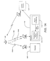
- FIGS. 1A - 1B illustrate a typical satellite transmission system and interference scenario
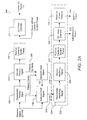
- FIGS. 2A - 2B are signal processing block diagrams of an apparatus and method of the invention.
- FIG. 3 is a plot of a received signal
- FIG. 4 is plot of a signal without interference
- FIG. 5 is a plot of a signal after the carrier frequency is removed
- FIG. 6 is a plot of a signal after the symbol phase is removed
- FIG. 7 is a plot of the interference and noise of a signal
- FIG. 8 is a plot of the interference and noise of a signal after the interference carrier frequency is removed.
- FIG. 9 is a plot of the interference and noise of a signal after the interference symbol phase is removed.
- FIG. 10 is a plot of the noise of a signal.
- FIGS. 1A - 1B illustrate a typical system and interference scenario of the present invention.
- FIG. 1A depicts a typical system of the present invention.
- One or more satellites 100 transmit signals 104, 106 to receivers 108, 110 in different geographical regions.
- the signals 104, 106 may have similar carrier frequencies and carry different information.
- the signals 104, 106 employ very similar carrier frequencies there is a potential for them to interfere. Interference is principally minimized through a geographic separation of the receivers 108, 110, i.e. through spatial diversity.
- the signals may be separated based on the direction to the transmitter (not shown in FIG. 1A ). In other words, a dish antenna may be focused in the direction of one transmitting satellite in favor of another.
- the transmission system may employ spotbeam antennas to further isolate the signals 104, 106 from one another and minimize interference.
- a desired signal 106 may be impinged by an interfering signal 104B.
- the signal 104A, associated with the interfering signal 104B, is intended for the receiver 108.
- the present invention employs comparison signal processing 114 as an adjunct to the regular signal processing 112 of the receiver 110 to accurately measure the power levels of different components of the received signal.
- the invention may operate as integral component of integrated receiver/decoder (IRD) of a direct satellite broadcast system or in a dedicated receiver. Furthermore, the invention is consistent with communication systems that are designed to operate with layered modulation. Signal comparison processing is fundamental to such systems and thus any benefits derived from the present invention may be made available to such systems for optimal system performance. These processes will be detailed in the discussion of FIGS. 2A - 2B hereafter.
- IRD integrated receiver/decoder
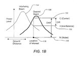
- FIG. 1B depicts the power profiles in a typical interference scenario.
- the peak effective isotropic radiated power (EIRP) of an interfering beam 104 may be higher than that of the desired beam 106, the CIR and CNR at a given location of interest 116 (e.g. the location of the antenna for receiver 110) must be sufficiently high for a receiver to work.
- the received signal at any location within the service footprint includes the desired signal 106, an interfering signal 104 and noise 118.
- the received power is the sum of the carrier power 120 at the location of interest 116 (i.e. from the carrier signal 106), the interference power 122 at the location of interest 116 (i.e. from the interfering signal 104B) and the noise 118.
- the invention is a precision method to calculate the relative power levels among signal, interference and noise.
- only one interference source is assumed in the following discussion.
- the principle is applicable and the processing technique is extendable for multiple interference sources of known modulation and FEC coding types.
- the locations of particular interest are wherever a strong interference source is present. This requires that an adequate power separation (such as 5 dB for QPSK, for example, depending on forward error correction (FEC) coding strength) among signal and interference sources exists for the invention method to work, which allows successive demodulation and decoding of the primary and interference signals.
- Each additional interfering signal is demodulated and decoded after subtracting all reconstructed higher power signals (as measured at the location of interest).
- Measurements made in the field (at each receiver) using the present invention may be used in satellite power control systems, part of a central control system 124, to achieve optimal carrier power vs. interference performance over a coverage area.
- the measurements may be fed back into the central control system 124 through a number of different mechanisms. For example, the measurements may be appended to regular communications between the IRD and a central system or the measuring IRD may transmit the power measurements back to the central system through a different means.
- FIGS. 2A - 2B are signal processing block diagrams of an apparatus and method of typical embodiments of the present invention.
- FIG. 2A is a block diagram of the apparatus.
- a demodulator 202 receives the signal which includes the primary signal, interference and noise and demodulates it to obtain the primary signal carrier.
- the decoder 204 receives the demodulated signal and decodes it to produce the primary signal symbols 206.
- a processor 208 also removes the carrier and symbol phase from the decoded signal.
- a measurement processor 210 measures the DC power of the signal without the carrier and symbol phase 212 as the estimated carrier power 214.
- the primary carrier and symbols 206 derived from the demodulation 202 and decoding 204 are used in a signal generator 216 to generate an ideal original carrier signal.
- the ideal signal is free of interference and noise, but is remodulated with the carrier phase.
- the ideal signal is then subtracted from the received signal by a subtractor 218.
- the ideal signal can be generated without the remodulated carrier phase and subtracted from the demodulated signal rather than from the received signal.
- the subtraction leaves the interference plus noise 220.
- the interference plus noise 220 result can then be evaluated in a number of different ways by an interference and noise processor 222.
- the interference and noise processor 222 is a single estimator which makes a power measurement of the aggregate interference plus noise 220. This embodiment does not distinguish between the contribution of the interfering signal and that of the noise. For broadcast systems which are only concerned with power control for non-interfering beams, a single measurement is all that is obtainable (i.e. there is no interfering signal).
- the interference and noise processor 222 is a subsystem which obtains discrete estimates of the interference and noise power levels. For separate interference and noise power measurement, the process of demodulation and decoding is repeated for this (I + N) signal in a second demodulator 224 and second decoder 226. As before, a carrier and decoded symbol phase are removed from the signal 227.
- noise power level 234 is estimated by subtracting the estimated interference power from the total interference and noise power in a processor 232.
- FIG. 2B is block diagram of the basic method of the present invention.
- the basic method of measuring signal properties comprises receiving a signal comprising a primary signal, noise and an interfering signal at block 236.
- the primary signal includes a carrier frequency and symbols.
- the primary signal is demodulated to remove the carrier frequency.
- the demodulated signal is decoded to obtain the symbols.
- the symbol phase is removed from the demodulated signal.
- a DC level of the demodulated signal with symbol phase removed is measured to estimate the power level of the primary signal at block 244.
- an ideal primary signal is generated from the carrier power and frequency and the symbols. Then the ideal primary signal is subtracted from the received signal to produce the noise and interfering signal at block 248.
- the noise and interference power are determined from the noise and interference signal 250.
- the noise and interference power may be determined as a combined value or separately as previously described.
- A is the amplitude of the signal
- p ( t ) represents the pulse shaping filter
- ⁇ t is the symbol interval
- ⁇ ( n ) is the phase of the n-th symbol
- n 0 ( t ) is the additive noise
- N is the number of symbols within the observation interval.
- Equation (4) provides an estimate of the total power, A 2 + N 0 .
- Equation (10) provides an estimate of the carrier power A 2 , as it includes little noise power N 0 N for a large number of samples, N. Alternately, equations (4) and (10) mabe be combined to solve for the two unknowns, A 2 and N 0 for a given N.
- FIGS. 3 - 10 show example intermediate results at various stages of the power measurement process.
- FIG. 3 depicts an example received signal including the primary (desired signal), the interfering signal and noise.
- the power of the primary signal is at 0 dB
- the interference is at -6 dB
- the noise is at -14.7 dB, yielding an effective CNR of 5.5 dB and an INR of 8.7 dB.
- the carrier frequency rotates the constellation around the origin.
- the effective CNR determines the thickness of the ring shape.
- FIG. 4 is plot of a signal without interference.
- the noise is at -5.5 dB with the signal at 0 dB, yielding a CNR of 5.5 dB.
- the CNR is identical to that of FIG. 3 , it is of interest to note that the distribution plot appears noisier.
- FIG. 5 is a the plot of the signal after the carrier frequency is removed from FIG. 3 through demodulation.
- the QPSK constellation is revealed by the four distinct rings.
- the interference frequency effectively rotates the four smaller constellations about their individual origins. In this case the INR determines the thickness of the individual rings.
- FIG. 6 is a plot of the received signal after the signal symbol phase is removed from FIG. 5 through decoding.
- the individual rings of FIG. 5 are now combined in a single quadrant.
- the DC signal component, representing the power level of the primary signal is depicted as the distance from the center of the ring to the origin.
- the interference frequency rotates the constellation about the center of the ring and the INR determines the thickness of the ring.
- FIG. 7 is a plot of the interference and noise of the signal after the ideal primary signal has been subtracted from FIG. 6 .
- the combined power may be measured directly from this plot without further processing, as represented by the mean-squared radius of the ring. ( FIG. 7 is the same as FIG. 6 , translated to the origin.)
- the interference frequency effectively rotates the constellation about the origin.
- the INR is related to the thickness of the ring.
- the effective CNR of FIG. 3 and the INR of FIG. 7 are analogous properties.
- FIG. 8 is a plot of the interference plus noise of the signal after the interference carrier frequency is removed from FIG. 7 through demodulating. Analogous to removing the carrier of the primary signal in FIG. 5 , the QPSK constellation of the interference signal is now visible. As the interference power is indicated by the distance of the node centers to the origin and the noise is indicated by the thickness of the nodes, the INR determines the tightness of the nodes.
- FIG. 9 is a plot of the interference plus noise after the interference symbol phase is removed from FIG. 8 through decoding.
- the DC signal component representing the power level of the interference signal, is the distance from the center of the circle to the origin.
- the INR determines the size of the node circle.
- FIG. 10 is a plot of the noise after the interference signal is removed from FIG. 9 .
- the noise power level is measured directly from this signal, as represented by the mean-squared radius of the circle.
Landscapes
- Engineering & Computer Science (AREA)
- Computer Networks & Wireless Communication (AREA)
- Signal Processing (AREA)
- Quality & Reliability (AREA)
- Physics & Mathematics (AREA)
- General Physics & Mathematics (AREA)
- Astronomy & Astrophysics (AREA)
- Aviation & Aerospace Engineering (AREA)
- Electromagnetism (AREA)
- Computing Systems (AREA)
- Monitoring And Testing Of Transmission In General (AREA)
- Noise Elimination (AREA)
- Radio Relay Systems (AREA)
Claims (19)
- Vorrichtung zum Messen von Signaleigenschaften, aufweisend:einen Demodulator (202), der in der Lage ist, ein Signal, das ein Primärsignal, ein Störsignal und ein Rauschen beinhaltet, zu empfangen, und das Primärsignal zu demodulieren, so dass eine Trägerfrequenz aus dem Primärsignal entfernt wird;einen Dekodierer (204), der in der Lage ist, das Primärsignal zu dekodieren, so dass Symbole aus dem Primärsignal erhalten werden;gekennzeichnet durch:einen Prozessor (208), der in der Lage ist, eine Leistung des Primärsignals anhand des demodulierten und dekodierten Primärsignals abzuschätzen;einen Signalgenerator (216), der in der Lage ist, ein ideales Primärsignal anhand der Trägerleistung und Trägerfrequenz und der Symbole zu erzeugen;einen Subtrahierer (218), der in der Lage ist, das ideale Primärsignal von dem empfangenen Signal zu subtrahieren, so dass sich daraus das Rauschen und das Störsignal ergibt; undeinen Prozessor (222), der in der Lage ist, das Rauschen und die Störleistung anhand des Rauschens und des Störsignals zu bestimmen.
- Vorrichtung nach Anspruch 1, ferner aufweisend einen Prozessor (208), der in der Lage ist, eine Symbolphase aus dem demodulierten Primärsignal zu entfernen, und wobei der Schritt des Abschätzens eines Leistungspegels des Primärsignals ein Messen eines Gleichstrompegels des demodulierten Primärsignals mit der entfernten Symbolphase aufweist.
- Vorrichtung nach Anspruch 1, wobei der Prozessor (222), der in der Lage ist, das Rauschen und die Störleistung zu bestimmen, das Rauschen und die Störleistung bestimmt, indem eine Kombination aus dem Rauschen und der Störleistung berechnet wird.
- Vorrichtung nach Anspruch 1, wobei das Störsignal einen Störträger und Störsymbole beinhaltet und der Prozessor (222), der in der Lage ist, das Rauschen und die Störleistung zu bestimmen, eine zweiten Demodulator (224) und einen Dekodierer (226) aufweist, der in der Lage ist, das Rauschen und die Störleistung zu bestimmen, indem das Störsignal demoduliert und dekodiert wird, so dass der Störträger und die Störsymbole entfernt und ein Signal mit einem Störsignal-Gleichstrompegel und einem Rauschpegel erzeugt wird.
- Vorrichtung nach Anspruch 4, wobei der Prozessor (222), der in der Lage ist, das Rauschen und die Störleistung zu bestimmen, ferner einen Prozessor (230) aufweist, der in der Lage ist, die Störleistung anhand des Störsignal-Gleichstrompegels zu berechnen.
- Vorrichtung nach Anspruch 5, wobei der Prozessor (222), der in der Lage ist, das Rauschen und die Störleistung zu bestimmen, ferner einen Subtrahierer (232) aufweist, der in der Lage ist, den Stör-Gleichstrompegel von dem Signal mit einem Störsignal-Gleichstrompegel und einem Rauschpegel zu subtrahieren, so dass die Rauschleistung berechnet wird.
- Vorrichtung nach Anspruch 1, wobei das empfangene Signal ferner zumindest ein zusätzliches Störsignal beinhaltet und jedes zusätzliche Störsignal demoduliert und dekodiert wird, so dass ein Träger und Symbole des jeweiligen zusätzlichen Störsignals nach dem Subtrahieren aller höheren Leistungssignale entfernt wird.
- Vorrichtung nach Anspruch 7, wobei ein Leistungspegel eines jeden zusätzlichen Störsignals anhand eines Gleichstrompegels des jeweiligen zusätzlichen Störsignals berechnet wird.
- Vorrichtung nach Anspruch 1, wobei die Primärsignalleistung und die Rausch- und Störleistung an ein zentrales System übertragen werden, so dass die Primär- und Störsignalleistung über einem Empfangsgebiet optimiert wird.
- Vorrichtung nach Anspruch 9, wobei die Primärsignalleistung und die Rausch- und Störleistung über einen Telefonwählvorgang an ein zentrales System übertragen werden.
- Verfahren zum Messen von Signaleigenschaften, das folgende Schritte beinhaltet:Empfangen eines Signals, das ein Primärsignal, ein Störsignal und ein Rauschen beinhaltet, wobei das Primärsignal eine Trägerfrequenz und Symbole (206) beinhaltet;Demodulieren des Primärsignals, so dass die Trägerfrequenz entfernt wird; Dekodieren des Primärsignals, so dass die Symbole (206) erhalten werden;gekennzeichnet durch:Abschätzen eines Leistungspegels des Primärsignals basierend auf dem demodulierten und dekodierten Primärsignal;Erzeugen eines idealen Primärsignals anhand der Trägerleistung und -frequenz und der Symbole; Subtrahieren des idealen Primärsignals von dem empfangenen Signal, so dass das Rauschen und das Störsignal erzeugt werden; undAbschätzen des Rauschens und der Störleistung anhand des Rauschens und des Störsignals.
- Verfahren nach Anspruch 11, ferner beinhaltend ein Entfernen einer Symbolphase aus dem demodulierten Primärsignal, und wobei der Schritt des Abschätzens eines Leistungspegels des Primärsignals ein Messen eines Gleichstrompegels des demodulierten Primärsignals mit der entfernten Symbolphase beinhaltet.
- Verfahren nach Anspruch 11, wobei das Störsignal einen Störträger und Störsymbole beinhaltet und das Abschätzen des Rauschens und der Störleistung ein Demodulieren und Dekodieren des Störsignals beinhaltet, so dass der Störträger und die Störsymbole entfernt werden und ein Signal mit einem Störsignal-Gleichstrompegel und einem Rauschpegel erzeugt wird.
- Verfahren nach Anspruch 13, ferner beinhaltend ein Abschätzen der Störleistung anhand des Störsignal-Gleichstrompegels.
- Verfahren nach Anspruch 14, ferner aufweisend ein Abschätzen der Rauschleistung durch Subtrahieren des Stör-Gleichstrompegels von dem Signal mit einem Störsignal-Gleichstrompegel und Geräuschpegel.
- Verfahren nach Anspruch 11, wobei das empfangene Signal ferner zumindest ein zusätzliches Störsignal beinhaltet und jedes zusätzliche Störsignal demoduliert und dekodiert wird, so dass ein Träger und Symbole des jeweiligen zusätzlichen Störsignals nach dem Subtrahieren aller höheren Leistungssignale entfernt werden.
- Verfahren nach Anspruch 16, wobei ein Leistungspegel eines jeden zusätzlichen Störsignals anhand eines Gleichstrompegels des jeweiligen zusätzlichen Störsignals berechnet wird.
- Verfahren nach Anspruch 11, wobei die Primärsignalleistung und die Rausch- und Störleistung an ein zentrales System übertragen werden, so dass die Primär- und Störsignalleistung über einem Empfangsgebiet optimiert wird.
- Vorrichtung nach Anspruch 11, wobei die Primärsignalleistung und die Rausch- und Störleistung über einen Telefonwählvorgang an ein zentrales System übertragen werden.
Applications Claiming Priority (3)
| Application Number | Priority Date | Filing Date | Title |
|---|---|---|---|
| US236414 | 2002-09-06 | ||
| US10/236,414 US7822154B2 (en) | 2001-04-27 | 2002-09-06 | Signal, interference and noise power measurement |
| PCT/US2003/026769 WO2004023676A1 (en) | 2002-09-06 | 2003-08-26 | Signal, interference and noise power measurement |
Publications (2)
| Publication Number | Publication Date |
|---|---|
| EP1547278A1 EP1547278A1 (de) | 2005-06-29 |
| EP1547278B1 true EP1547278B1 (de) | 2009-12-23 |
Family
ID=31977641
Family Applications (1)
| Application Number | Title | Priority Date | Filing Date |
|---|---|---|---|
| EP03794510A Expired - Lifetime EP1547278B1 (de) | 2002-09-06 | 2003-08-26 | Signal-, störungs- und rauschleistungsmessung |
Country Status (11)
| Country | Link |
|---|---|
| US (1) | US7822154B2 (de) |
| EP (1) | EP1547278B1 (de) |
| AR (1) | AR041158A1 (de) |
| AT (1) | ATE453254T1 (de) |
| CA (1) | CA2495855C (de) |
| DE (1) | DE60330691D1 (de) |
| ES (1) | ES2338547T3 (de) |
| IL (1) | IL166883A (de) |
| NO (1) | NO334384B1 (de) |
| TW (1) | TWI240507B (de) |
| WO (1) | WO2004023676A1 (de) |
Families Citing this family (25)
| Publication number | Priority date | Publication date | Assignee | Title |
|---|---|---|---|---|
| US7423987B2 (en) | 2001-04-27 | 2008-09-09 | The Directv Group, Inc. | Feeder link configurations to support layered modulation for digital signals |
| JP3920137B2 (ja) * | 2002-04-26 | 2007-05-30 | ティーオーエー株式会社 | デジタル無線受信機 |
| WO2005101839A2 (en) | 2004-04-12 | 2005-10-27 | The Directv Group, Inc. | Shifted channel characteristics for mitigating co-channel interference |
| US7672285B2 (en) * | 2004-06-28 | 2010-03-02 | Dtvg Licensing, Inc. | Method and apparatus for minimizing co-channel interference by scrambling |
| US8213553B2 (en) * | 2004-04-12 | 2012-07-03 | The Directv Group, Inc. | Method and apparatus for identifying co-channel interference |
| US7161988B2 (en) * | 2004-04-12 | 2007-01-09 | The Directv Group, Inc. | Method and apparatus for minimizing co-channel interference |
| US8493942B2 (en) * | 2005-08-01 | 2013-07-23 | Qualcomm Incorporated | Interference cancellation in wireless communication |
| US7773942B2 (en) | 2006-08-29 | 2010-08-10 | Wildblue Communications, Inc. | Redundant communication path for satellite communication data |
| GB0706427D0 (en) * | 2007-04-02 | 2007-05-09 | British Telecomm | Data recovery scheme |
| DE102008006628A1 (de) * | 2008-01-29 | 2009-07-30 | Deutsche Telekom Ag | Verfahren und Vorrichtung zur automatischen Überprüfung der GNSS Signalqualität in Mautgeräten |
| WO2010029484A1 (en) * | 2008-09-09 | 2010-03-18 | Philips Intellectual Property & Standards Gmbh | Velocity determination apparatus |
| US20100105346A1 (en) * | 2008-10-24 | 2010-04-29 | Anritsu Company | Method to detect interference in wireless signals |
| US9571142B2 (en) * | 2008-10-24 | 2017-02-14 | Anritsu Company | Apparatus to detect interference in wireless signals |
| US20110311007A1 (en) * | 2009-02-16 | 2011-12-22 | Elektrobit System Test Oy | Method and an Apparatus for Forming Signal Estimates |
| JP4792513B2 (ja) * | 2009-04-27 | 2011-10-12 | 株式会社エヌ・ティ・ティ・ドコモ | 無線通信システムで使用される方法及び通信端末 |
| CN101959237B (zh) * | 2009-07-14 | 2013-06-05 | 大唐移动通信设备有限公司 | 提高系统信息更新成功率的方法、系统及装置 |
| CN102083139B (zh) * | 2009-11-26 | 2013-01-09 | 中国移动通信集团上海有限公司 | 数据转发控制方法、装置及系统 |
| CN101873621B (zh) * | 2010-06-13 | 2013-01-30 | 工业和信息化部电信传输研究所 | 移动多媒体终端的接收机性能测试方法及系统 |
| WO2014120292A1 (en) * | 2012-10-19 | 2014-08-07 | Imra America, Inc. | Noise detection, diagnostics, and control of mode-locked lasers |
| US9203659B2 (en) * | 2013-06-07 | 2015-12-01 | Samsung Electronics Co., Ltd. | Computing system with interference classification mechanism and method of operation thereof |
| US9674836B2 (en) * | 2014-01-27 | 2017-06-06 | Spectrum Effect, Inc. | Method and system for coexistence of radar and communication systems |
| DE102014214923A1 (de) * | 2014-07-30 | 2016-02-25 | Rohde & Schwarz Gmbh & Co. Kg | Verfahren und Vorrichtung zur Ermittlung eines Schätzwertes für eine Rauschleistung |
| CN109873695B (zh) * | 2017-12-05 | 2022-05-06 | 航天信息股份有限公司 | 一种基于昆虫触角仿真的干扰波形插入点确定方法及装置 |
| CN113438916B (zh) * | 2019-03-11 | 2024-12-13 | 奥林巴斯株式会社 | 内窥镜和内窥镜的制造方法 |
| US12598505B2 (en) | 2021-03-05 | 2026-04-07 | Telefonaktiebolaget Lm Ericsson (Publ) | Interference detection mechanisms for microwave radio link transceivers |
Family Cites Families (252)
| Publication number | Priority date | Publication date | Assignee | Title |
|---|---|---|---|---|
| US158619A (en) * | 1875-01-12 | Improvement in clock-movement holders | ||
| NL257397A (de) | 1959-10-08 | |||
| US3383598A (en) | 1965-02-15 | 1968-05-14 | Space General Corp | Transmitter for multiplexed phase modulated singaling system |
| US3879664A (en) | 1973-05-07 | 1975-04-22 | Signatron | High speed digital communication receiver |
| US3878468A (en) | 1974-01-30 | 1975-04-15 | Bell Telephone Labor Inc | Joint equalization and carrier recovery adaptation in data transmission systems |
| US4039961A (en) | 1974-09-12 | 1977-08-02 | Nippon Telegraph And Telephone Public Corporation | Demodulator for combined digital amplitude and phase keyed modulation signals |
| US3974449A (en) | 1975-03-21 | 1976-08-10 | Bell Telephone Laboratories, Incorporated | Joint decision feedback equalization and carrier recovery adaptation in data transmission systems |
| JPS522253A (en) | 1975-06-24 | 1977-01-08 | Kokusai Denshin Denwa Co Ltd <Kdd> | Non-linearity compensation cicuit for high frequency amplifier |
| JPS5816802B2 (ja) | 1978-04-17 | 1983-04-02 | ケイディディ株式会社 | 高周波増幅器の非線形補償回路 |
| USRE31351E (en) | 1978-08-04 | 1983-08-16 | Bell Telephone Laboratories, Incorporated | Feedback nonlinear equalization of modulated data signals |
| US4213095A (en) | 1978-08-04 | 1980-07-15 | Bell Telephone Laboratories, Incorporated | Feedforward nonlinear equalization of modulated data signals |
| US4384355A (en) | 1979-10-15 | 1983-05-17 | Bell Telephone Laboratories, Incorporated | Control of coefficient drift for fractionally spaced equalizers |
| US4253184A (en) | 1979-11-06 | 1981-02-24 | Bell Telephone Laboratories, Incorporated | Phase-jitter compensation using periodic harmonically related components |
| US4422175A (en) | 1981-06-11 | 1983-12-20 | Racal-Vadic, Inc. | Constrained adaptive equalizer |
| FR2510331A1 (fr) | 1981-07-23 | 1983-01-28 | Leclert Alain | Circuit de regeneration d'une onde porteuse |
| US4416015A (en) | 1981-12-30 | 1983-11-15 | Bell Telephone Laboratories, Incorporated | Timing acquisition in voiceband data sets |
| US4500984A (en) | 1982-09-29 | 1985-02-19 | International Telecommunications Satellite Organization | Equalizer for reducing crosstalk between two FDM/FM carriers in a satellite communications system |
| US4519084A (en) | 1982-09-29 | 1985-05-21 | At&T Bell Laboratories | Matched filter for combating multipath fading |
| JPS59124950A (ja) | 1982-12-29 | 1984-07-19 | Mitsubishi Petrochem Co Ltd | ポリフエニレンエ−テル樹脂組成物 |
| JPS59193658A (ja) | 1983-04-18 | 1984-11-02 | Nec Corp | 擬似誤り検出回路 |
| FR2546010B1 (fr) | 1983-05-11 | 1985-07-12 | Trt Telecom Radio Electr | Dispositif d'egalisation en frequence porteuse commande a partir de la bande de base |
| FR2546008B1 (fr) | 1983-05-11 | 1985-07-12 | Labo Electronique Physique | Circuit d'egalisation adaptative et de demodulation conjointes |
| US4637017A (en) | 1984-05-21 | 1987-01-13 | Communications Satellite Corporation | Monitoring of input backoff in time division multiple access communication satellites |
| US4709374A (en) | 1984-07-05 | 1987-11-24 | American Telephone And Telegraph Company | Technique for decision-directed equalizer train/retrain |
| GB2164823A (en) | 1984-09-17 | 1986-03-26 | Philips Electronic Associated | Television transmitter |
| US4896369A (en) | 1984-12-28 | 1990-01-23 | Harris Corporation | Optimal satellite TWT power allocation process for achieving requested availability and maintaining stability in ALPC-type networks |
| US4654863A (en) | 1985-05-23 | 1987-03-31 | At&T Bell Laboratories | Wideband adaptive prediction |
| US4647873A (en) | 1985-07-19 | 1987-03-03 | General Dynamics, Pomona Division | Adaptive linear FM sweep corrective system |
| DE3539818A1 (de) | 1985-11-09 | 1987-05-14 | Bosch Gmbh Robert | Verfahren zum digitalen uebertragen von daten und sprache |
| AU589084B2 (en) | 1986-02-08 | 1989-09-28 | Nec Corporation | Multilevel modulator capable of producing a composite modulated signal comprising a quadrature amplitude modulated component and a phase modulated component |
| GB8606572D0 (en) | 1986-03-17 | 1986-04-23 | Hewlett Packard Ltd | Analysis of digital radio transmissions |
| DE3642213C2 (de) | 1986-12-10 | 1994-01-27 | Siemens Ag | Satelliten-Nachrichtenübertragungssystem |
| JPH0773218B2 (ja) | 1987-04-21 | 1995-08-02 | 沖電気工業株式会社 | Adpcm符号化・復号化器 |
| EP0296822B1 (de) | 1987-06-23 | 1993-12-08 | Nec Corporation | Träger/Rausch-Detektor für digitale Übertragungssysteme |
| US4878030A (en) | 1987-10-23 | 1989-10-31 | Ford Aerospace & Communications Corporation | Linearizer for microwave amplifier |
| US4800573A (en) | 1987-11-19 | 1989-01-24 | American Telephone And Telegraph Company | Equalization arrangement |
| US4829543A (en) | 1987-12-04 | 1989-05-09 | Motorola, Inc. | Phase-coherent TDMA quadrature receiver for multipath fading channels |
| US4847864A (en) | 1988-06-22 | 1989-07-11 | American Telephone And Telegraph Company | Phase jitter compensation arrangement using an adaptive IIR filter |
| US4992747A (en) | 1988-08-16 | 1991-02-12 | Myers Glen A | Multiple reuse of an FM band |
| US5043734A (en) | 1988-12-22 | 1991-08-27 | Hughes Aircraft Company | Discrete autofocus for ultra-high resolution synthetic aperture radar |
| US5016273A (en) | 1989-01-09 | 1991-05-14 | At&E Corporation | Dual communication mode video tape recorder |
| US4993047A (en) | 1989-09-05 | 1991-02-12 | At&T Bell Laboratories | Volterra linearizer for digital transmission |
| DE4001592A1 (de) | 1989-10-25 | 1991-05-02 | Philips Patentverwaltung | Empfaenger fuer digitales uebertragungssystem |
| US5835857A (en) | 1990-03-19 | 1998-11-10 | Celsat America, Inc. | Position determination for reducing unauthorized use of a communication system |
| US5206886A (en) | 1990-04-16 | 1993-04-27 | Telebit Corporation | Method and apparatus for correcting for clock and carrier frequency offset, and phase jitter in mulicarrier modems |
| US5121414A (en) | 1990-08-09 | 1992-06-09 | Motorola, Inc. | Carrier frequency offset equalization |
| US5703874A (en) | 1990-12-05 | 1997-12-30 | Interdigital Technology Corporation | Broadband CDMA overlay system and method |
| US5581229A (en) | 1990-12-19 | 1996-12-03 | Hunt Technologies, Inc. | Communication system for a power distribution line |
| US5111155A (en) | 1991-03-04 | 1992-05-05 | Motorola, Inc. | Distortion compensation means and method |
| US5229765A (en) | 1991-05-08 | 1993-07-20 | Halliburton Logging Services, Inc. | SP noise cancellation technique |
| US5233632A (en) | 1991-05-10 | 1993-08-03 | Motorola, Inc. | Communication system receiver apparatus and method for fast carrier acquisition |
| US5337014A (en) | 1991-06-21 | 1994-08-09 | Harris Corporation | Phase noise measurements utilizing a frequency down conversion/multiplier, direct spectrum measurement technique |
| CA2076099A1 (en) | 1991-09-03 | 1993-03-04 | Howard Leroy Lester | Automatic simulcast alignment |
| US5285480A (en) | 1991-09-03 | 1994-02-08 | General Electric Company | Adaptive MLSE-VA receiver for digital cellular radio |
| JP2776094B2 (ja) | 1991-10-31 | 1998-07-16 | 日本電気株式会社 | 可変変調通信方法 |
| US5221908A (en) | 1991-11-29 | 1993-06-22 | General Electric Co. | Wideband integrated distortion equalizer |
| JPH05211670A (ja) | 1992-01-14 | 1993-08-20 | Nec Corp | 搬送波電力対雑音電力比検出回路 |
| US5206889A (en) | 1992-01-17 | 1993-04-27 | Hewlett-Packard Company | Timing interpolator |
| US5285474A (en) | 1992-06-12 | 1994-02-08 | The Board Of Trustees Of The Leland Stanford, Junior University | Method for equalizing a multicarrier signal in a multicarrier communication system |
| US5237292A (en) | 1992-07-01 | 1993-08-17 | Space Systems/Loral | Quadrature amplitude modulation system with compensation for transmission system characteristics |
| JP3135999B2 (ja) | 1992-09-18 | 2001-02-19 | リーダー電子株式会社 | Cn比測定装置 |
| FR2696295B1 (fr) | 1992-09-29 | 1994-12-09 | Europ Agence Spatiale | Dispositif pour corriger les distorsions non-linéaires d'un amplificateur électronique. |
| AU677300B2 (en) | 1993-02-17 | 1997-04-17 | Motorola Solutions, Inc. | Multiple-modulation communication system |
| US5329311A (en) | 1993-05-11 | 1994-07-12 | The University Of British Columbia | System for determining noise content of a video signal in the disclosure |
| US5471508A (en) | 1993-08-20 | 1995-11-28 | Hitachi America, Ltd. | Carrier recovery system using acquisition and tracking modes and automatic carrier-to-noise estimation |
| US5513215A (en) | 1993-09-20 | 1996-04-30 | Glenayre Electronics, Inc. | High speed simulcast data system using adaptive compensation |
| JP3560991B2 (ja) | 1993-09-20 | 2004-09-02 | 株式会社東芝 | 適応型最尤系列推定装置 |
| US6088590A (en) * | 1993-11-01 | 2000-07-11 | Omnipoint Corporation | Method and system for mobile controlled handoff and link maintenance in spread spectrum communication |
| US5412325A (en) | 1993-12-23 | 1995-05-02 | Hughes Aircraft Company | Phase noise measurement system and method |
| US5619503A (en) | 1994-01-11 | 1997-04-08 | Ericsson Inc. | Cellular/satellite communications system with improved frequency re-use |
| US5577067A (en) | 1994-02-22 | 1996-11-19 | Comsonics, Inc. | Data acquisition and storage system for telecommunication equipment to facilitate alignment and realignment of the telecommunications equipment |
| US5642358A (en) | 1994-04-08 | 1997-06-24 | Ericsson Inc. | Multiple beamwidth phased array |
| US5430770A (en) | 1994-04-22 | 1995-07-04 | Rockwell International Corp. | Method and apparatus for composite signal separation and PSK/AM/FM demodulation |
| EP0683561A1 (de) | 1994-05-18 | 1995-11-22 | Guan-Wu Wang | Kostengünstiger, rauscharmer Frequenzumsetzer mit Mischer in Selbsterregung für Satellitenempfänger |
| JP2561028B2 (ja) | 1994-05-26 | 1996-12-04 | 日本電気株式会社 | サイドローブキャンセラ |
| KR100247373B1 (ko) | 1994-08-31 | 2000-03-15 | 이데이 노부유끼 | 신호 송신 장치, 신호 수신 장치, 및 신호 송수신방법 |
| FR2724522B1 (fr) | 1994-09-09 | 1997-01-17 | France Telecom | Procede et dispositif de codage-decodage de canal multiresolution en television numerique haute definition et conventionnelle |
| US5625640A (en) | 1994-09-16 | 1997-04-29 | Hughes Electronics | Apparatus for and method of broadcast satellite network return-link signal transmission |
| US5937004A (en) | 1994-10-13 | 1999-08-10 | Fasulo, Ii; Albert Joseph | Apparatus and method for verifying performance of digital processing board of an RF receiver |
| FR2727590B1 (fr) | 1994-11-24 | 1996-12-27 | Alcatel Espace | Charge utile de satellite a canaux transparents integres |
| US5603084C1 (en) * | 1995-03-02 | 2001-06-05 | Ericsson Inc | Method and apparatus for remotely programming a cellular radiotelephone |
| US5568520A (en) | 1995-03-09 | 1996-10-22 | Ericsson Inc. | Slope drift and offset compensation in zero-IF receivers |
| JP2705623B2 (ja) | 1995-03-22 | 1998-01-28 | 日本電気株式会社 | ダイバーシチ送受信方法及び送受信機 |
| US5898695A (en) | 1995-03-29 | 1999-04-27 | Hitachi, Ltd. | Decoder for compressed and multiplexed video and audio data |
| US5751766A (en) | 1995-04-27 | 1998-05-12 | Applied Signal Technology, Inc. | Non-invasive digital communications test system |
| US5608331A (en) | 1995-06-06 | 1997-03-04 | Hughes Electronics | Noise measurement test system |
| US5793818A (en) | 1995-06-07 | 1998-08-11 | Discovision Associates | Signal processing system |
| ZA965340B (en) | 1995-06-30 | 1997-01-27 | Interdigital Tech Corp | Code division multiple access (cdma) communication system |
| US5671253A (en) | 1995-07-12 | 1997-09-23 | Thomson Consumer Electronics, Inc. | Apparatus for demodulating and decoding video signals encoded in different formats |
| US5606286A (en) | 1995-07-27 | 1997-02-25 | Bains; Devendar S. | Predistortion linearization |
| DE19538302C2 (de) | 1995-10-16 | 2001-03-22 | Bosch Gmbh Robert | Verfahren zur terrestrischen Übertragung digitaler Signale |
| JP3788823B2 (ja) | 1995-10-27 | 2006-06-21 | 株式会社東芝 | 動画像符号化装置および動画像復号化装置 |
| GB2307152B (en) | 1995-11-10 | 1999-04-07 | Motorola Ltd | Method and apparatus for enhanced communication capability while maintaining standard channel modulation compatibility |
| US5956373A (en) | 1995-11-17 | 1999-09-21 | Usa Digital Radio Partners, L.P. | AM compatible digital audio broadcasting signal transmision using digitally modulated orthogonal noise-like sequences |
| US6772182B1 (en) | 1995-12-08 | 2004-08-03 | The United States Of America As Represented By The Secretary Of The Navy | Signal processing method for improving the signal-to-noise ratio of a noise-dominated channel and a matched-phase noise filter for implementing the same |
| US5828710A (en) | 1995-12-11 | 1998-10-27 | Delco Electronics Corporation | AFC frequency synchronization network |
| CN1111986C (zh) | 1996-04-12 | 2003-06-18 | Ntt移动通信网株式会社 | 测量接收的信噪比的方法、设备及传输功率控制系统 |
| US6055278A (en) | 1996-04-26 | 2000-04-25 | C-Cor.Net Corporation | Linearization circuits and methods |
| US5815531A (en) | 1996-06-12 | 1998-09-29 | Ericsson Inc. | Transmitter for encoded data bits |
| US5732113A (en) | 1996-06-20 | 1998-03-24 | Stanford University | Timing and frequency synchronization of OFDM signals |
| JP3272246B2 (ja) | 1996-07-12 | 2002-04-08 | 株式会社東芝 | デジタル放送受信装置 |
| JPH1054855A (ja) | 1996-08-09 | 1998-02-24 | Advantest Corp | スペクトラムアナライザ |
| FI963317A7 (fi) | 1996-08-26 | 1998-02-27 | Nokia Technology Gmbh | Monitasoisten, kaksiulotteisten modulaatioaakkostojen kantoaaltosynkronointi |
| US6411797B1 (en) | 1996-09-20 | 2002-06-25 | Itt Manufacturing Enterprises, Inc. | Method and apparatus for performance characterization of satellite transponders |
| EP0836303B1 (de) | 1996-10-14 | 2003-02-26 | Ntt Mobile Communications Network Inc. | Verfahren und Vorrichtung zur Verringerung des Verhältnisses von Spitzen-zu Durchschnittsleistung |
| DE19646164A1 (de) | 1996-11-08 | 1998-05-14 | Deutsche Telekom Ag | Verfahren zur Übertragung digitaler Signale |
| DE19647833B4 (de) | 1996-11-19 | 2005-07-07 | Deutsches Zentrum für Luft- und Raumfahrt e.V. | Verfahren zur gleichzeitigen Funkübertragung digitaler Daten zwischen mehreren Teilnehmerstationen und einer Basisstation |
| US5966416A (en) | 1996-11-21 | 1999-10-12 | Dsp Group, Inc. | Verification of PN synchronization in a spread-spectrum communications receiver |
| US5960040A (en) | 1996-12-05 | 1999-09-28 | Raytheon Company | Communication signal processors and methods |
| JP3346198B2 (ja) | 1996-12-10 | 2002-11-18 | 富士ゼロックス株式会社 | 能動消音装置 |
| JPH10190497A (ja) | 1996-12-27 | 1998-07-21 | Fujitsu Ltd | Sir測定装置 |
| US5978652A (en) | 1997-01-10 | 1999-11-02 | Space Systems/Loral, Inc. | Common direct broadcasting service system |
| US5970156A (en) | 1997-02-14 | 1999-10-19 | Telefonaktiebolaget Lm Ericsson | Method and apparatus for reducing periodic interference in audio signals |
| US6078645A (en) | 1997-02-20 | 2000-06-20 | Lucent Technologies Inc. | Apparatus and method for monitoring full duplex data communications |
| JP3586348B2 (ja) * | 1997-03-05 | 2004-11-10 | 富士通株式会社 | 信号対干渉電力比測定装置及び信号対干渉電力比測定方法並びにcdma通信方式下での送信電力制御方法 |
| US5870443A (en) | 1997-03-19 | 1999-02-09 | Hughes Electronics Corporation | Symbol timing recovery and tracking method for burst-mode digital communications |
| US6212360B1 (en) | 1997-04-09 | 2001-04-03 | Ge Capital Spacenet Services, Inc. | Methods and apparatus for controlling earth-station transmitted power in a VSAT network |
| US6040800A (en) | 1997-04-22 | 2000-03-21 | Ericsson Inc. | Systems and methods for locating remote terminals in radiocommunication systems |
| US5905943A (en) | 1997-04-29 | 1999-05-18 | Globalstar L.P. | System for generating and using global radio frequency maps |
| US6314441B1 (en) | 1997-04-30 | 2001-11-06 | Agere Systems Inc | Robust method for providing tap leakage in adaptive equalizer systems |
| US5970098A (en) | 1997-05-02 | 1999-10-19 | Globespan Technologies, Inc. | Multilevel encoder |
| CA2286780A1 (en) | 1997-05-02 | 1998-11-12 | Giacomo Porcelli | High latitude geostationary satellite system |
| JPH10327204A (ja) | 1997-05-26 | 1998-12-08 | Nec Corp | 等化器を用いた位相同期ループ回路 |
| JPH10336262A (ja) | 1997-05-28 | 1998-12-18 | Ikegami Tsushinki Co Ltd | ディジタル信号の伝送品質測定回路 |
| US6019318A (en) | 1997-06-16 | 2000-02-01 | Hugehs Electronics Corporation | Coordinatable system of inclined geosynchronous satellite orbits |
| US5870439A (en) | 1997-06-18 | 1999-02-09 | Lsi Logic Corporation | Satellite receiver tuner chip having reduced digital noise interference |
| US6134282A (en) | 1997-06-18 | 2000-10-17 | Lsi Logic Corporation | Method for lowpass filter calibration in a satellite receiver |
| US5999793A (en) | 1997-06-18 | 1999-12-07 | Lsi Logic Corporation | Satellite receiver tuner chip with frequency synthesizer having an externally configurable charge pump |
| US5819157A (en) | 1997-06-18 | 1998-10-06 | Lsi Logic Corporation | Reduced power tuner chip with integrated voltage regulator for a satellite receiver system |
| US6539050B1 (en) | 1997-06-26 | 2003-03-25 | Hughes Electronics Corporation | Method for transmitting wideband signals via a communication system adapted for narrow-band signal transmission |
| US5966412A (en) | 1997-06-30 | 1999-10-12 | Thomson Consumer Electronics, Inc. | Apparatus and method for processing a Quadrature Amplitude Modulated (QAM) signal |
| US6072841A (en) | 1997-07-01 | 2000-06-06 | Hughes Electronics Corporation | Block phase estimator for the coherent detection of non-differentially phase modulated data bursts on rician fading channels |
| US6049566A (en) | 1997-07-24 | 2000-04-11 | Trw Inc. | High efficiency signaling with minimum spacecraft hardware |
| US5970429A (en) | 1997-08-08 | 1999-10-19 | Lucent Technologies, Inc. | Method and apparatus for measuring electrical noise in devices |
| US6108374A (en) | 1997-08-25 | 2000-08-22 | Lucent Technologies, Inc. | System and method for measuring channel quality information |
| US6125148A (en) | 1997-08-29 | 2000-09-26 | Telefonaktiebolaget Lm Ericsson | Method for demodulating information in a communication system that supports multiple modulation schemes |
| US6052586A (en) | 1997-08-29 | 2000-04-18 | Ericsson Inc. | Fixed and mobile satellite radiotelephone systems and methods with capacity sharing |
| US5940025A (en) | 1997-09-15 | 1999-08-17 | Raytheon Company | Noise cancellation method and apparatus |
| US6434384B1 (en) | 1997-10-17 | 2002-08-13 | The Boeing Company | Non-uniform multi-beam satellite communications system and method |
| US6272679B1 (en) | 1997-10-17 | 2001-08-07 | Hughes Electronics Corporation | Dynamic interference optimization method for satellites transmitting multiple beams with common frequencies |
| US6002713A (en) | 1997-10-22 | 1999-12-14 | Pc Tel, Inc. | PCM modem equalizer with adaptive compensation for robbed bit signalling |
| US6477398B1 (en) | 1997-11-13 | 2002-11-05 | Randell L. Mills | Resonant magnetic susceptibility imaging (ReMSI) |
| US5966048A (en) | 1997-11-25 | 1999-10-12 | Hughes Electronics Corporation | Low IMD amplification method and apparatus |
| JP3392028B2 (ja) | 1997-11-28 | 2003-03-31 | 株式会社ケンウッド | 階層化伝送ディジタル復調器 |
| AU2274899A (en) | 1997-12-18 | 1999-07-12 | Sony International (Europe) Gmbh | N-port direct receiver |
| PT929164E (pt) | 1997-12-18 | 2000-06-30 | Europ Des Satellites Soc | Metodo e aparelho de determinacao do ponto operacional de um amplificador nao linear num canal de comunicacao |
| US6128357A (en) | 1997-12-24 | 2000-10-03 | Mitsubishi Electric Information Technology Center America, Inc (Ita) | Data receiver having variable rate symbol timing recovery with non-synchronized sampling |
| US5952834A (en) | 1998-01-14 | 1999-09-14 | Advanced Testing Technologies, Inc. | Low noise signal synthesizer and phase noise measurement system |
| US5909454A (en) | 1998-01-20 | 1999-06-01 | General Instrument Corporation | Intermediate rate applications of punctured convolutional codes for 8PSK trellis modulation over satellite channels |
| US6084919A (en) | 1998-01-30 | 2000-07-04 | Motorola, Inc. | Communication unit having spectral adaptability |
| US6131013A (en) | 1998-01-30 | 2000-10-10 | Motorola, Inc. | Method and apparatus for performing targeted interference suppression |
| US6219095B1 (en) | 1998-02-10 | 2001-04-17 | Wavetek Corporation | Noise measurement system |
| IL123739A (en) | 1998-03-19 | 2001-11-25 | Infineon Technologies Ag | Method and equipment for restoring clock timing in XDSL modems and especially VDSL modems |
| US6313885B1 (en) | 1998-03-25 | 2001-11-06 | Samsung Electronics Co., Ltd. | DTV receiver with baseband equalization filters for QAM signal and for VSB signal which employ common elements |
| US6141534A (en) | 1998-03-25 | 2000-10-31 | Spacecode Llc | Communication satellite system with dynamic downlink resource allocation |
| US6192088B1 (en) | 1998-03-31 | 2001-02-20 | Lucent Technologies Inc. | Carrier recovery system |
| US6433835B1 (en) | 1998-04-17 | 2002-08-13 | Encamera Sciences Corporation | Expanded information capacity for existing communication transmission systems |
| US6657978B1 (en) | 1998-04-23 | 2003-12-02 | Transworld Communications (Usa), Inc. | Optimized integrated high capacity digital satellite trunking network |
| US6535497B1 (en) | 1998-05-11 | 2003-03-18 | Telefonaktiebolaget Lm Ericsson (Publ) | Methods and systems for multiplexing of multiple users for enhanced capacity radiocommunications |
| JP2966396B1 (ja) | 1998-05-22 | 1999-10-25 | 株式会社ケンウッド | Bsディジタル放送受信機 |
| US6597750B1 (en) | 1998-06-19 | 2003-07-22 | Thomson Licensing S.A. | Opposite polarization interference cancellation in satellite communication |
| US6426822B1 (en) | 1998-06-25 | 2002-07-30 | Ipicom, Inc. | Method and apparatus for reducing non-linear characteristics of a signal modulator by coherent data collection |
| JP2000031944A (ja) | 1998-07-07 | 2000-01-28 | Matsushita Electric Ind Co Ltd | 送信装置並びに受信装置及びデータ伝送方法 |
| US6304594B1 (en) | 1998-07-27 | 2001-10-16 | General Dynamics Government Systems Corporation | Interference detection and avoidance technique |
| US6452977B1 (en) | 1998-09-15 | 2002-09-17 | Ibiquity Digital Corporation | Method and apparatus for AM compatible digital broadcasting |
| AU6257399A (en) | 1998-09-18 | 2000-04-10 | Hesham El Gamal | Method and constructions for space-time codes for psk constellations for spatialdiversity in multiple-element antenna systems |
| DE69920737T2 (de) | 1998-11-03 | 2005-10-13 | Broadcom Corp., Irvine | Qam/vsb zweimodenempfänger |
| US6246717B1 (en) | 1998-11-03 | 2001-06-12 | Tektronix, Inc. | Measurement test set and method for in-service measurements of phase noise |
| US6404819B1 (en) | 1998-11-20 | 2002-06-11 | Lucent Technologies Inc. | System and method for generating NRZ signals from RZ signals in communications networks |
| US6320919B1 (en) | 1998-11-30 | 2001-11-20 | Ericsson Inc. | Adaptive channel characterization using decoded symbols |
| US6104747A (en) | 1998-11-30 | 2000-08-15 | Motorola, Inc. | Method for determining optimum number of complex samples for coherent averaging in a communication system |
| US6335951B1 (en) | 1998-12-04 | 2002-01-01 | Itt Manufacturing Enterprises, Inc. | Programmable waveform generator for a global positioning system |
| US6515713B1 (en) | 1998-12-31 | 2003-02-04 | Lg Electronics Inc. | Method and apparatus which compensates for channel distortion |
| US6166601A (en) | 1999-01-07 | 2000-12-26 | Wiseband Communications Ltd. | Super-linear multi-carrier power amplifier |
| US6678520B1 (en) | 1999-01-07 | 2004-01-13 | Hughes Electronics Corporation | Method and apparatus for providing wideband services using medium and low earth orbit satellites |
| TW559668B (en) | 1999-02-08 | 2003-11-01 | Advantest Corp | Apparatus for and method of measuring a jitter |
| US6529715B1 (en) | 1999-02-26 | 2003-03-04 | Lucent Technologies Inc. | Amplifier architecture for multi-carrier wide-band communications |
| JP2000278341A (ja) | 1999-03-25 | 2000-10-06 | Sanyo Electric Co Ltd | 直交位相復調回路 |
| EP1041712B1 (de) | 1999-03-31 | 2009-01-28 | NTT Mobile Communications Network Inc. | Vorwärtskopplungsverstärker |
| US6369648B1 (en) | 1999-04-21 | 2002-04-09 | Hughes Electronics Corporation | Linear traveling wave tube amplifier utilizing input drive limiter for optimization |
| US6177836B1 (en) | 1999-05-07 | 2001-01-23 | The Aerospace Corporation | Feed forward linearized traveling wave tube |
| EA004457B1 (ru) | 1999-06-18 | 2004-04-29 | Сосьете Эропеен Де Сателит С.А. | Способ и устройство определения характеристик компонент канала связи |
| US6556639B1 (en) | 1999-06-24 | 2003-04-29 | Ibiquity Digital Corporation | Method and apparatus for determining transmission mode and synchronization for a digital audio broadcasting signal |
| GB9915417D0 (en) | 1999-07-02 | 1999-09-01 | Nds Ltd | Improvements in or relating to hierarchical coding |
| US6775521B1 (en) | 1999-08-09 | 2004-08-10 | Broadcom Corporation | Bad frame indicator for radio telephone receivers |
| US6574235B1 (en) | 1999-08-12 | 2003-06-03 | Ericsson Inc. | Methods of receiving co-channel signals by channel separation and successive cancellation and related receivers |
| KR100314113B1 (ko) | 1999-08-25 | 2001-11-15 | 구자홍 | 정합 필터 및 필터링방법, 이를 이용한 다매체 디지털 방송수신 장치 |
| KR20010019997A (ko) | 1999-08-31 | 2001-03-15 | 박종섭 | 아이엠티-2000 시스템에서의 광대역 씨디엠에이 신호용 채널 시뮬레이터 |
| US6249180B1 (en) | 1999-09-08 | 2001-06-19 | Atmel Corporation | Phase noise and additive noise estimation in a QAM demodulator |
| US6560295B1 (en) | 1999-09-15 | 2003-05-06 | Hughes Electronics Corporation | Method of generating space-time codes for generalized layered space-time architectures |
| US7161931B1 (en) | 1999-09-20 | 2007-01-09 | Broadcom Corporation | Voice and data exchange over a packet based network |
| US6535545B1 (en) | 1999-10-15 | 2003-03-18 | Rf Waves Ltd. | RF modem utilizing saw resonator and correlator and communications transceiver constructed therefrom |
| US7073116B1 (en) | 1999-11-23 | 2006-07-04 | Thomson Licensing | Error detection/correction coding for hierarchical QAM transmission systems |
| US7079585B1 (en) | 1999-11-23 | 2006-07-18 | Thomson Licensing | Gray encoding for hierarchical QAM transmission systems |
| US6535801B1 (en) | 2000-01-28 | 2003-03-18 | General Dynamics Decision Systems, Inc. | Method and apparatus for accurately determining the position of satellites in geosynchronous orbits |
| JP2001223665A (ja) | 2000-02-08 | 2001-08-17 | Matsushita Electric Ind Co Ltd | 信号符号化伝送装置、信号復号化受信装置、およびプログラム記録媒体 |
| CA2302004A1 (en) | 2000-03-22 | 2001-09-22 | Vajira N. S. Samarasooriya | Method and system for achieving carrier frequency synchronization in a high speed receiver |
| US6307435B1 (en) | 2000-03-23 | 2001-10-23 | The Aerospace Corporation | High power amplifier linearization method using modified linear-log model predistortion |
| US6429740B1 (en) | 2000-03-23 | 2002-08-06 | The Aerospace Corporation | High power amplifier linearization method using extended saleh model predistortion |
| US6741662B1 (en) | 2000-04-17 | 2004-05-25 | Intel Corporation | Transmitter linearization using fast predistortion |
| US7885314B1 (en) | 2000-05-02 | 2011-02-08 | Kenneth Scott Walley | Cancellation system and method for a wireless positioning system |
| US6377116B1 (en) | 2000-05-08 | 2002-04-23 | Iowa State University Research Foundation, Inc. | Pre-distorter and corresponding method for deriving same |
| JP3786343B2 (ja) | 2000-05-12 | 2006-06-14 | 日本ビクター株式会社 | 光ディスク再生装置 |
| US6956841B1 (en) | 2000-05-24 | 2005-10-18 | Nokia Networks Oy | Receiver and method of receiving a desired signal |
| SE517030C2 (sv) | 2000-06-06 | 2002-04-02 | Ericsson Telefon Ab L M | Metod och anordning för val av modulerings- och kodningsregler i ett radiokommunikationssystem |
| US6297691B1 (en) | 2000-06-09 | 2001-10-02 | Rosemount Inc. | Method and apparatus for demodulating coherent and non-coherent modulated signals |
| JP2002009728A (ja) | 2000-06-23 | 2002-01-11 | Hitachi Kokusai Electric Inc | 直交周波数分割多重変調伝送装置 |
| US7154958B2 (en) | 2000-07-05 | 2006-12-26 | Texas Instruments Incorporated | Code division multiple access wireless system with time reversed space time block transmitter diversity |
| WO2002011302A2 (en) | 2000-08-02 | 2002-02-07 | Mobiles Satellite Ventures Lp | Coordinated satellite-terrestrial frequency reuse |
| US6522683B1 (en) | 2000-08-10 | 2003-02-18 | Qualcomm, Incorporated | Method and apparatus for adaptive linear equalization for walsh covered modulation |
| DE10043743A1 (de) | 2000-09-05 | 2002-03-14 | Infineon Technologies Ag | Automatische Frequenzkorrektur für Mobilfunkempfänger |
| US6718184B1 (en) | 2000-09-28 | 2004-04-06 | Lucent Technologies Inc. | Method and system for adaptive signal processing for an antenna array |
| JP3602047B2 (ja) | 2000-10-05 | 2004-12-15 | シャープ株式会社 | 階層化伝送デジタル信号復調装置 |
| US6745050B1 (en) | 2000-10-23 | 2004-06-01 | Massachusetts Institute Of Technology | Multichannel multiuser detection |
| US7190683B2 (en) | 2000-10-27 | 2007-03-13 | L-3 Communications Corporation | Two-dimensional channel bonding in a hybrid CDMA/FDMA fixed wireless access system to provide finely variable rate channels |
| US7042956B2 (en) | 2000-11-06 | 2006-05-09 | Hesham El-Gamal | Method and system for utilizing space-time codes for block fading channels |
| JP3387918B2 (ja) | 2000-12-04 | 2003-03-17 | 富士通株式会社 | 時間等化方法及び装置 |
| US6567762B2 (en) | 2000-12-22 | 2003-05-20 | Agilent Technologies, Inc. | Dynamic range extension apparatus and method |
| US6731700B1 (en) | 2001-01-04 | 2004-05-04 | Comsys Communication & Signal Processing Ltd. | Soft decision output generator |
| JP3545726B2 (ja) | 2001-02-27 | 2004-07-21 | 松下電器産業株式会社 | 受信側装置 |
| US20030002471A1 (en) | 2001-03-06 | 2003-01-02 | Crawford James A. | Method for estimating carrier-to-noise-plus-interference ratio (CNIR) for OFDM waveforms and the use thereof for diversity antenna branch selection |
| US6922439B2 (en) | 2001-03-16 | 2005-07-26 | Advantest Corporation | Apparatus for and method of measuring jitter |
| US7471735B2 (en) | 2001-04-27 | 2008-12-30 | The Directv Group, Inc. | Maximizing power and spectral efficiencies for layered and conventional modulations |
| GB2375016B (en) | 2001-04-27 | 2005-03-16 | Tandberg Television Asa | Satellite up-link fade compensation |
| US7173981B1 (en) | 2001-04-27 | 2007-02-06 | The Directv Group, Inc. | Dual layer signal processing in a layered modulation digital signal system |
| US7778365B2 (en) | 2001-04-27 | 2010-08-17 | The Directv Group, Inc. | Satellite TWTA on-line non-linearity measurement |
| US7209524B2 (en) | 2001-04-27 | 2007-04-24 | The Directv Group, Inc. | Layered modulation for digital signals |
| US7639759B2 (en) | 2001-04-27 | 2009-12-29 | The Directv Group, Inc. | Carrier to noise ratio estimations from a received signal |
| US7453933B2 (en) | 2001-05-04 | 2008-11-18 | Lucent Technologies Inc. | Method of estimating a signal-to-interference+noise ratio (SINR) using data samples |
| US7046739B2 (en) | 2001-05-18 | 2006-05-16 | Southwest Research Institute | Pre-distortion of input signals to form constant envelope signal outputs |
| US7106792B2 (en) | 2001-06-04 | 2006-09-12 | Qualcomm, Inc. | Method and apparatus for estimating the signal to interference-plus-noise ratio of a wireless channel |
| US6956924B2 (en) | 2001-08-14 | 2005-10-18 | Northrop Grumman Corporation | Efficient implementation of a decision directed phase locked loop (DD-PLL) for use with short block code in digital communication systems |
| US7239876B2 (en) | 2001-09-06 | 2007-07-03 | Motorola, Inc. | Method for increased location receiver sensitivity |
| US7039122B2 (en) | 2001-10-17 | 2006-05-02 | Itt Manufacturing Enterprises, Inc. | Method and apparatus for generating a composite signal |
| US6700442B2 (en) | 2001-11-20 | 2004-03-02 | Thomas Quang Ha | N way phase cancellation power amplifier |
| US7263119B1 (en) | 2001-11-29 | 2007-08-28 | Marvell International Ltd. | Decoding method and apparatus |
| ES2282528T3 (es) | 2002-02-05 | 2007-10-16 | Hughes Electronics Corporation | Preprocesamiento de las señales superpuestas en un esquema de transmision digital de modulacion estratificada para utilizar receptores legados. |
| US7065153B2 (en) | 2002-02-06 | 2006-06-20 | The Boeing Company | High speed monolithic microwave integrated circuit (MMIC) quadrature phase shift keying (QPSK) and quadrature amplitude modulation (QAM) modulators |
| KR20030076259A (ko) | 2002-03-19 | 2003-09-26 | 술저 헥시스 악티엔게젤샤프트 | 열교환기 일체형 연료 전지 배터리 |
| US7197084B2 (en) | 2002-03-27 | 2007-03-27 | Qualcomm Incorporated | Precoding for a multipath channel in a MIMO system |
| US6809587B2 (en) | 2002-04-23 | 2004-10-26 | Mitec Telecom Inc. | Active predistorting linearizer with agile bypass circuit for safe mode operation |
| US20070121718A1 (en) | 2002-06-06 | 2007-05-31 | Chin-Liang Wang | System and Method for Time-Domain Equalization in Discrete Multi-tone Systems |
| US7274876B2 (en) | 2002-06-06 | 2007-09-25 | At&T Corp. | Integrated electrical/optical hybrid communication system with revertive hitless switch |
| WO2004004193A2 (en) | 2002-07-01 | 2004-01-08 | The Directv Group, Inc. | Improving hierarchical 8psk performance |
| US6885708B2 (en) | 2002-07-18 | 2005-04-26 | Motorola, Inc. | Training prefix modulation method and receiver |
| US8229003B2 (en) | 2002-09-06 | 2012-07-24 | Koninklijke Philips Electronics N.V. | Parameter encoding for an improved ATSC DTV system |
| US7230480B2 (en) | 2002-10-25 | 2007-06-12 | The Directv Group, Inc. | Estimating the operating point on a non-linear traveling wave tube amplifier |
| EP1559253B1 (de) | 2002-10-25 | 2012-01-04 | The Directv Group, Inc. | Maximierung von leistungs- und spektraleffizienzen für geschichtete und herkömmliche modulationen |
| US7529312B2 (en) | 2002-10-25 | 2009-05-05 | The Directv Group, Inc. | Layered modulation for terrestrial ATSC applications |
| US7548598B2 (en) | 2003-04-07 | 2009-06-16 | Harris Corporation | Method and apparatus for iteratively improving the performance of coded and interleaved communication systems |
| US6999510B2 (en) | 2003-04-18 | 2006-02-14 | Optichron, Inc. | Nonlinear inversion |
| US7230992B2 (en) | 2003-11-26 | 2007-06-12 | Delphi Technologies, Inc. | Method to create hierarchical modulation in OFDM |
-
2002
- 2002-09-06 US US10/236,414 patent/US7822154B2/en not_active Expired - Lifetime
-
2003
- 2003-08-26 AT AT03794510T patent/ATE453254T1/de not_active IP Right Cessation
- 2003-08-26 DE DE60330691T patent/DE60330691D1/de not_active Expired - Lifetime
- 2003-08-26 EP EP03794510A patent/EP1547278B1/de not_active Expired - Lifetime
- 2003-08-26 WO PCT/US2003/026769 patent/WO2004023676A1/en not_active Ceased
- 2003-08-26 ES ES03794510T patent/ES2338547T3/es not_active Expired - Lifetime
- 2003-08-26 CA CA2495855A patent/CA2495855C/en not_active Expired - Fee Related
- 2003-09-04 AR ARP030103220A patent/AR041158A1/es not_active Application Discontinuation
- 2003-09-04 TW TW092124550A patent/TWI240507B/zh not_active IP Right Cessation
-
2005
- 2005-02-14 IL IL166883A patent/IL166883A/en not_active IP Right Cessation
- 2005-03-30 NO NO20051593A patent/NO334384B1/no not_active IP Right Cessation
Also Published As
| Publication number | Publication date |
|---|---|
| EP1547278A1 (de) | 2005-06-29 |
| ATE453254T1 (de) | 2010-01-15 |
| US20030219069A1 (en) | 2003-11-27 |
| NO334384B1 (no) | 2014-02-24 |
| NO20051593L (no) | 2005-06-03 |
| AR041158A1 (es) | 2005-05-04 |
| WO2004023676A1 (en) | 2004-03-18 |
| US7822154B2 (en) | 2010-10-26 |
| TWI240507B (en) | 2005-09-21 |
| CA2495855A1 (en) | 2004-03-18 |
| ES2338547T3 (es) | 2010-05-10 |
| CA2495855C (en) | 2010-11-23 |
| TW200425658A (en) | 2004-11-16 |
| IL166883A (en) | 2010-12-30 |
| DE60330691D1 (de) | 2010-02-04 |
Similar Documents
| Publication | Publication Date | Title |
|---|---|---|
| US7822154B2 (en) | Signal, interference and noise power measurement | |
| US6430216B1 (en) | Rake receiver for spread spectrum signal demodulation | |
| Sakhnini et al. | Near-field coherent radar sensing using a massive MIMO communication testbed | |
| US6154171A (en) | Low-power satellite-based geopositioning system | |
| US10416278B2 (en) | Radio receiver for determining location of a signal source | |
| Kozhaya et al. | Unveiling starlink for PNT | |
| US8195241B2 (en) | High-performance cellular telephone receiver | |
| US8804808B1 (en) | Dynamic equalization systems and methods for use with a receiver for a multipath channel | |
| KR20010072616A (ko) | 도플러 시프트된 신호의 주파수 불확실성 범위를 좁히기위한 방법 및 장치 | |
| EP2659637B1 (de) | Schätzung des Frequenzfehlers eines Tonsignals mit verbreiterter Erfassungsbereich | |
| CN111095015A (zh) | 一种用于通过利用每载波多信道施照器源的一无源雷达系统检测一目标的方法及系统 | |
| US20090161797A1 (en) | Satellite detection of automatic identification system signals | |
| Wei et al. | Time-of-arrival estimation for integrated satellite navigation and communication signals | |
| US6947474B2 (en) | Rake receiver for spread spectrum signal demodulation | |
| RU2607475C2 (ru) | Способ координированной обработки сигналов, передаваемых радиомаяками | |
| CN113765578A (zh) | 一种通信卫星地面干扰源定位方法、装置、设备及存储介质 | |
| JP4514953B2 (ja) | スペクトラム拡散通信システムのアクセスチャネルアクイジションにおいて周波数およびタイミングの不確かさを決定するシステムおよび装置 | |
| Komodromos et al. | Signal parameter estimation and demodulation of the OneWeb Ku-Band downlink | |
| WO1998008319A1 (en) | Rake receiver for spread spectrum signal demodulation | |
| MX2013013820A (es) | Metodo para localizar una terminal en una superficie de un area de cobertura por medio de una red de telecomunicacion por medio de un satelite mutihaz. | |
| WO1998008319A9 (en) | Rake receiver for spread spectrum signal demodulation | |
| RU2708383C2 (ru) | Способ обработки сигналов дальности с модулированной смещенной несущей | |
| Domínguez et al. | Unified Navigation and Communication Hybrid Terminal | |
| Jardak et al. | Referenceless Doppler Shift and Rate Estimation for Opportunistic Positioning With OneWeb Signals | |
| US8442020B1 (en) | Phase compensation system and method to correct M-code dual sideband distortion |
Legal Events
| Date | Code | Title | Description |
|---|---|---|---|
| PUAI | Public reference made under article 153(3) epc to a published international application that has entered the european phase |
Free format text: ORIGINAL CODE: 0009012 |
|
| 17P | Request for examination filed |
Effective date: 20050321 |
|
| AK | Designated contracting states |
Kind code of ref document: A1 Designated state(s): AT BE BG CH CY CZ DE DK EE ES FI FR GB GR HU IE IT LI LU MC NL PT RO SE SI SK TR |
|
| 17Q | First examination report despatched |
Effective date: 20070803 |
|
| GRAP | Despatch of communication of intention to grant a patent |
Free format text: ORIGINAL CODE: EPIDOSNIGR1 |
|
| GRAS | Grant fee paid |
Free format text: ORIGINAL CODE: EPIDOSNIGR3 |
|
| GRAA | (expected) grant |
Free format text: ORIGINAL CODE: 0009210 |
|
| AK | Designated contracting states |
Kind code of ref document: B1 Designated state(s): AT BE BG CH CY CZ DE DK EE ES FI FR GB GR HU IE IT LI LU MC NL PT RO SE SI SK TR |
|
| REG | Reference to a national code |
Ref country code: GB Ref legal event code: FG4D |
|
| REG | Reference to a national code |
Ref country code: CH Ref legal event code: EP |
|
| REG | Reference to a national code |
Ref country code: IE Ref legal event code: FG4D |
|
| REF | Corresponds to: |
Ref document number: 60330691 Country of ref document: DE Date of ref document: 20100204 Kind code of ref document: P |
|
| PG25 | Lapsed in a contracting state [announced via postgrant information from national office to epo] |
Ref country code: FI Free format text: LAPSE BECAUSE OF FAILURE TO SUBMIT A TRANSLATION OF THE DESCRIPTION OR TO PAY THE FEE WITHIN THE PRESCRIBED TIME-LIMIT Effective date: 20091223 Ref country code: SE Free format text: LAPSE BECAUSE OF FAILURE TO SUBMIT A TRANSLATION OF THE DESCRIPTION OR TO PAY THE FEE WITHIN THE PRESCRIBED TIME-LIMIT Effective date: 20091223 |
|
| REG | Reference to a national code |
Ref country code: ES Ref legal event code: FG2A Ref document number: 2338547 Country of ref document: ES Kind code of ref document: T3 |
|
| PG25 | Lapsed in a contracting state [announced via postgrant information from national office to epo] |
Ref country code: SI Free format text: LAPSE BECAUSE OF FAILURE TO SUBMIT A TRANSLATION OF THE DESCRIPTION OR TO PAY THE FEE WITHIN THE PRESCRIBED TIME-LIMIT Effective date: 20091223 |
|
| PG25 | Lapsed in a contracting state [announced via postgrant information from national office to epo] |
Ref country code: AT Free format text: LAPSE BECAUSE OF FAILURE TO SUBMIT A TRANSLATION OF THE DESCRIPTION OR TO PAY THE FEE WITHIN THE PRESCRIBED TIME-LIMIT Effective date: 20091223 |
|
| PG25 | Lapsed in a contracting state [announced via postgrant information from national office to epo] |
Ref country code: RO Free format text: LAPSE BECAUSE OF FAILURE TO SUBMIT A TRANSLATION OF THE DESCRIPTION OR TO PAY THE FEE WITHIN THE PRESCRIBED TIME-LIMIT Effective date: 20091223 Ref country code: PT Free format text: LAPSE BECAUSE OF FAILURE TO SUBMIT A TRANSLATION OF THE DESCRIPTION OR TO PAY THE FEE WITHIN THE PRESCRIBED TIME-LIMIT Effective date: 20100423 Ref country code: BG Free format text: LAPSE BECAUSE OF FAILURE TO SUBMIT A TRANSLATION OF THE DESCRIPTION OR TO PAY THE FEE WITHIN THE PRESCRIBED TIME-LIMIT Effective date: 20100323 Ref country code: EE Free format text: LAPSE BECAUSE OF FAILURE TO SUBMIT A TRANSLATION OF THE DESCRIPTION OR TO PAY THE FEE WITHIN THE PRESCRIBED TIME-LIMIT Effective date: 20091223 |
|
| PG25 | Lapsed in a contracting state [announced via postgrant information from national office to epo] |
Ref country code: BE Free format text: LAPSE BECAUSE OF FAILURE TO SUBMIT A TRANSLATION OF THE DESCRIPTION OR TO PAY THE FEE WITHIN THE PRESCRIBED TIME-LIMIT Effective date: 20091223 Ref country code: SK Free format text: LAPSE BECAUSE OF FAILURE TO SUBMIT A TRANSLATION OF THE DESCRIPTION OR TO PAY THE FEE WITHIN THE PRESCRIBED TIME-LIMIT Effective date: 20091223 Ref country code: CZ Free format text: LAPSE BECAUSE OF FAILURE TO SUBMIT A TRANSLATION OF THE DESCRIPTION OR TO PAY THE FEE WITHIN THE PRESCRIBED TIME-LIMIT Effective date: 20091223 |
|
| PG25 | Lapsed in a contracting state [announced via postgrant information from national office to epo] |
Ref country code: GR Free format text: LAPSE BECAUSE OF FAILURE TO SUBMIT A TRANSLATION OF THE DESCRIPTION OR TO PAY THE FEE WITHIN THE PRESCRIBED TIME-LIMIT Effective date: 20100324 Ref country code: CY Free format text: LAPSE BECAUSE OF FAILURE TO SUBMIT A TRANSLATION OF THE DESCRIPTION OR TO PAY THE FEE WITHIN THE PRESCRIBED TIME-LIMIT Effective date: 20091223 |
|
| PLBE | No opposition filed within time limit |
Free format text: ORIGINAL CODE: 0009261 |
|
| STAA | Information on the status of an ep patent application or granted ep patent |
Free format text: STATUS: NO OPPOSITION FILED WITHIN TIME LIMIT |
|
| 26N | No opposition filed |
Effective date: 20100924 |
|
| PG25 | Lapsed in a contracting state [announced via postgrant information from national office to epo] |
Ref country code: DK Free format text: LAPSE BECAUSE OF FAILURE TO SUBMIT A TRANSLATION OF THE DESCRIPTION OR TO PAY THE FEE WITHIN THE PRESCRIBED TIME-LIMIT Effective date: 20091223 |
|
| PG25 | Lapsed in a contracting state [announced via postgrant information from national office to epo] |
Ref country code: MC Free format text: LAPSE BECAUSE OF NON-PAYMENT OF DUE FEES Effective date: 20100831 |
|
| REG | Reference to a national code |
Ref country code: CH Ref legal event code: PL |
|
| PG25 | Lapsed in a contracting state [announced via postgrant information from national office to epo] |
Ref country code: CH Free format text: LAPSE BECAUSE OF NON-PAYMENT OF DUE FEES Effective date: 20100831 Ref country code: LI Free format text: LAPSE BECAUSE OF NON-PAYMENT OF DUE FEES Effective date: 20100831 |
|
| PG25 | Lapsed in a contracting state [announced via postgrant information from national office to epo] |
Ref country code: IE Free format text: LAPSE BECAUSE OF NON-PAYMENT OF DUE FEES Effective date: 20100826 |
|
| PG25 | Lapsed in a contracting state [announced via postgrant information from national office to epo] |
Ref country code: HU Free format text: LAPSE BECAUSE OF FAILURE TO SUBMIT A TRANSLATION OF THE DESCRIPTION OR TO PAY THE FEE WITHIN THE PRESCRIBED TIME-LIMIT Effective date: 20100624 Ref country code: LU Free format text: LAPSE BECAUSE OF NON-PAYMENT OF DUE FEES Effective date: 20100826 |
|
| PG25 | Lapsed in a contracting state [announced via postgrant information from national office to epo] |
Ref country code: TR Free format text: LAPSE BECAUSE OF FAILURE TO SUBMIT A TRANSLATION OF THE DESCRIPTION OR TO PAY THE FEE WITHIN THE PRESCRIBED TIME-LIMIT Effective date: 20091223 |
|
| REG | Reference to a national code |
Ref country code: FR Ref legal event code: PLFP Year of fee payment: 14 |
|
| PGFP | Annual fee paid to national office [announced via postgrant information from national office to epo] |
Ref country code: NL Payment date: 20160805 Year of fee payment: 14 |
|
| PGFP | Annual fee paid to national office [announced via postgrant information from national office to epo] |
Ref country code: IT Payment date: 20160811 Year of fee payment: 14 Ref country code: DE Payment date: 20160831 Year of fee payment: 14 Ref country code: GB Payment date: 20160725 Year of fee payment: 14 |
|
| PGFP | Annual fee paid to national office [announced via postgrant information from national office to epo] |
Ref country code: FR Payment date: 20160719 Year of fee payment: 14 |
|
| PGFP | Annual fee paid to national office [announced via postgrant information from national office to epo] |
Ref country code: ES Payment date: 20160801 Year of fee payment: 14 |
|
| REG | Reference to a national code |
Ref country code: DE Ref legal event code: R119 Ref document number: 60330691 Country of ref document: DE |
|
| REG | Reference to a national code |
Ref country code: NL Ref legal event code: MM Effective date: 20170901 |
|
| GBPC | Gb: european patent ceased through non-payment of renewal fee |
Effective date: 20170826 |
|
| REG | Reference to a national code |
Ref country code: FR Ref legal event code: ST Effective date: 20180430 |
|
| PG25 | Lapsed in a contracting state [announced via postgrant information from national office to epo] |
Ref country code: NL Free format text: LAPSE BECAUSE OF NON-PAYMENT OF DUE FEES Effective date: 20170901 |
|
| PG25 | Lapsed in a contracting state [announced via postgrant information from national office to epo] |
Ref country code: GB Free format text: LAPSE BECAUSE OF NON-PAYMENT OF DUE FEES Effective date: 20170826 Ref country code: DE Free format text: LAPSE BECAUSE OF NON-PAYMENT OF DUE FEES Effective date: 20180301 |
|
| PG25 | Lapsed in a contracting state [announced via postgrant information from national office to epo] |
Ref country code: IT Free format text: LAPSE BECAUSE OF NON-PAYMENT OF DUE FEES Effective date: 20170826 Ref country code: FR Free format text: LAPSE BECAUSE OF NON-PAYMENT OF DUE FEES Effective date: 20170831 |
|
| REG | Reference to a national code |
Ref country code: ES Ref legal event code: FD2A Effective date: 20181025 |
|
| PG25 | Lapsed in a contracting state [announced via postgrant information from national office to epo] |
Ref country code: ES Free format text: LAPSE BECAUSE OF NON-PAYMENT OF DUE FEES Effective date: 20170827 |