US6922439B2 - Apparatus for and method of measuring jitter - Google Patents
Apparatus for and method of measuring jitter Download PDFInfo
- Publication number
- US6922439B2 US6922439B2 US09/811,153 US81115301A US6922439B2 US 6922439 B2 US6922439 B2 US 6922439B2 US 81115301 A US81115301 A US 81115301A US 6922439 B2 US6922439 B2 US 6922439B2
- Authority
- US
- United States
- Prior art keywords
- jitter
- sequence
- period
- under measurement
- signal under
- Prior art date
- Legal status (The legal status is an assumption and is not a legal conclusion. Google has not performed a legal analysis and makes no representation as to the accuracy of the status listed.)
- Expired - Lifetime, expires
Links
Images
Classifications
-
- G—PHYSICS
- G01—MEASURING; TESTING
- G01R—MEASURING ELECTRIC VARIABLES; MEASURING MAGNETIC VARIABLES
- G01R29/00—Arrangements for measuring or indicating electric quantities not covered by groups G01R19/00 - G01R27/00
- G01R29/02—Measuring characteristics of individual pulses, e.g. deviation from pulse flatness, rise time or duration
- G01R29/027—Indicating that a pulse characteristic is either above or below a predetermined value or within or beyond a predetermined range of values
- G01R29/0273—Indicating that a pulse characteristic is either above or below a predetermined value or within or beyond a predetermined range of values the pulse characteristic being duration, i.e. width (indicating that frequency of pulses is above or below a certain limit)
-
- G—PHYSICS
- G01—MEASURING; TESTING
- G01R—MEASURING ELECTRIC VARIABLES; MEASURING MAGNETIC VARIABLES
- G01R29/00—Arrangements for measuring or indicating electric quantities not covered by groups G01R19/00 - G01R27/00
- G01R29/26—Measuring noise figure; Measuring signal-to-noise ratio
-
- H—ELECTRICITY
- H04—ELECTRIC COMMUNICATION TECHNIQUE
- H04L—TRANSMISSION OF DIGITAL INFORMATION, e.g. TELEGRAPHIC COMMUNICATION
- H04L1/00—Arrangements for detecting or preventing errors in the information received
- H04L1/20—Arrangements for detecting or preventing errors in the information received using signal quality detector
- H04L1/205—Arrangements for detecting or preventing errors in the information received using signal quality detector jitter monitoring
Definitions
- the present invention relates to an apparatus for and a method of measuring period jitter that are applied to a measurement of jitter of, for example, a microprocessor clock.
- a time interval analyzer and/or an oscilloscope have conventionally been used for the measurement of period jitter.
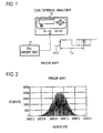
- the method of these apparatus is called Zero-crossing Method, in which, as shown in FIG. 1 , a clock signal (a signal under measurement) x(t) from, for example, a PLL (Phase-Locked Loop) under test 11 is supplied to a time interval analyzer 12 .
- a clock signal (a signal under measurement) x(t) from, for example, a PLL (Phase-Locked Loop) under test 11 is supplied to a time interval analyzer 12 .
- a next rising edge following one rising edge fluctuates against the preceding rising edge as indicated by dotted lines. That is, a time interval T p between the two rising edges, namely a period fluctuates.
- a time interval between zero-crossings (period) of the signal under measurement is measured, a fluctuation of period is measured by a histogram analysis, and its histogram is displayed as shown in FIG. 2.
- a time interval analyzer is described in, for example, “Phase Digitizing Sharpens Timing Measurements” by D.Chu, IEEE Spectrum, pp. 28-32, 1988, and “A Method of Serial Data Jitter Analysis Using One-Shot Time Interval Measurements” by J. Wilstrup, Proceedings of IEEE International Test Conference, pp. 819-823, 1998.
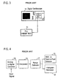
- Tektronix, Inc. and LeCroy Co. have recently been providing digital oscilloscopes each being able to measure a jitter using an interpolation method.
- this jitter measurement method using the interpolation method interpolation-based jitter measurement method
- an interval between data having signal values close to a zero-crossing out of measured data of a sampled signal under measurement is interpolated to estimate a timing of zero-crossing. That is, in order to measure a fluctuation of period, a time interval between zero-crossings (period) is estimated using a data interpolation with a small error.
- a signal under measurement x(t) from the PLL under test 11 is inputted to a digital oscilloscope 14 .
- the digital oscilloscope 14 as shown in FIG. 4 , the inputted signal under measurement x(t) is converted into a digital data sequence by an analog-to-digital converter 15 .
- a data-interpolation is applied to an interval between data having signal values close to a zero-crossing in the digital data sequence by an interpolator 16 .
- a time interval between zero-crossings is measured by a period estimator 17 .
- a histogram of the measured values is displayed on a histogram estimating part 18 , and a root-mean-square value and a peak-to-peak value of fluctuations of the measured time intervals are obtained by an RMS & Peak-to-Peak Detector 19 .
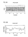
- RMS & Peak-to-Peak Detector 19 For example, in the case in which a signal under measurement x(t) has a waveform shown in FIG. 5A , its period jitters are measured as shown in FIG. 5 B.
- a time interval between zero-crossings is measured. Therefore a correct measurement can be performed.
- this method repeatedly measures jitter but includes an intermediate dead-time between measurements, there is a problem that it takes a long time to acquire a number of data that are required for a histogram analysis.
- an interpolation-based jitter measurement method in which a wide-band oscilloscope and an interpolation method are combined, there is a problem that a histogram of jitter cannot accurately be estimated, and a jitter values are overestimated (overestimation).
- the time interval analyzer method measure a root-mean-square value of jitter as 7.72 ps while the interpolation method measures, a root-mean-square of 8.47 ps, that is larger than the value estimated by the time interval analyzer method.
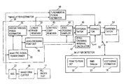
- inventors of the present invention have proposed a method of measuring a jitter as described below in an article entitled “Extraction of Peak-to-Peak and RMS Sinusoidal Jitter Using an Analytic Signal Method” by T. J. Yamaguchi, M. Soma, M. Ishida, and T. Ohmi, Proceedings of 18th IEEE VLSI Test Symposium, pp. 395-402, 2000. That is, as shown in FIG.
- an analog clock waveform from a PLL (Phase locked loop) circuit under test 11 is converted into a digital clock signal x c (t) by an analog-to-digital converter 22 , and the digital clock signal x c (t) is supplied to a Hilbert pair generator 24 acting as an analytic signal transforming part 23 , where the digital clock signal x c (t) is transformed into an analytic signal z c (t).
- PLL Phase locked loop
- a clock signal x c (t) is defined as follows.
- x c ( t ) A c cos(2 ⁇ f c t+ ⁇ c ⁇ ( t ))
- the A c and the f c are nominal values of amplitude and frequency of a clock signal respectively
- the ⁇ c is an initial phase angle
- the ⁇ (t) is a phase fluctuation that is called an instantaneous phase noise.
- an instantaneous phase ⁇ (t) of the clock signal x c (t) can be estimated by the instantaneous phase estimator 26 as follows.
- ⁇ ( t ) [2 ⁇ f c t+ ⁇ c ⁇ ( t )]mod 2 ⁇ [rad]
- a linear phase is removed from this instantaneous phase ⁇ (t) by a linear phase remover 27 to obtain a phase noise waveform ⁇ (t). That is, in the linear phase remover 27 , a continuous phase converting part 28 applies a phase unwrap method to the instantaneous phase ⁇ (t) to obtain a continuous instantaneous phase ⁇ (t) as follows.
- phase unwrap method is shown in “A New Phase Unwrapping Algorithm” by Jose M. Tribolet, IEEE Trans. Acoust., Speech, Signal Processing, vol. ASSP-25, pp. 170-177, 1977 and in “On Frequency-Domain and Time-Domain Phase Unwrapping” by Kuno P. Zimmermann, Proc. IEEE. vol. 75, pp. 519-520, 1987.
- An instantaneous linear phase of a continuous instantaneous phase ⁇ (t), i.e., a linear instantaneous phase [2 ⁇ f c t+ ⁇ c ] of a jitter-free ideal signal is estimated by a linear phase evaluator 29 using a linear trend estimating method. That is, an instantaneous linear phase of a continuous instantaneous phase ⁇ (t) is estimated by applying a linear line fitting by least squares method to the above continuous phase ⁇ (t).
- This estimated linear phase [2 ⁇ f c t+ ⁇ c ] is subtracted from the continuous phase ⁇ (t) by a subtracting part 31 to obtain a variable term ⁇ (t) of the instantaneous phase ⁇ (t), i.e., an instantaneous phase noise waveform as follows.
- ⁇ ( t ) ⁇ ( t )
- ⁇ ⁇ ⁇ ⁇ pp max k ⁇ ( ⁇ ⁇ ⁇ ⁇ ⁇ [ k ] ) - min k ⁇ ( ⁇ ⁇ ⁇ ⁇ [ k ] )
- the timing jitter sequence ⁇ [n] is also inputted to a root-mean-square detector 33 , where a root-mean-square (RMS) value of the timing jitter sequence ⁇ [n] is calculated using following equation to obtain a root-mean-square value ⁇ RMS of timing jitters.
- This method is referred to as the ⁇ method, since a peak value of timing jitter (peak-to-peak value) and a root-mean-square value of timing jitters are obtained from the instantaneous phase noise waveform ⁇ (t). Further, an instantaneous phase noise waveform ⁇ (t) is sometimes written as a instantaneous phase noise ⁇ (t) or a phase noise waveform ⁇ (t).
- a timing jitter can be measured at high speed with relatively high accuracy.
- an instantaneous phase noise waveform of a signal under measurement can be obtained, the instantaneous phase noise waveform is sampled at a timing close to each zero-crossing point (approximated zero-crossing point) of the signal under measurement to estimate a timing jitter sequence of the signal under measurement, a difference sequence of this timing jitter sequence is calculated to measure a period jitter sequence, and values of this period jitter sequence is corrected by multipling a ratio of a fundamental period of the signal under measurement and time interval values between the approximated zero-crossing points.
- An analytic signal of a fundamental cosine wave x(t) of an input signal (may sometimes be written as a signal under measurement) is given by an equation (1) as follows.
- a timing jitter sequence is obtained by sampling an instantaneous phase noise waveform ⁇ (t) at a timing (referred to as an approximated zero-crossing point) closest to each zero-crossing point of a real part x(t) of an analytic signal z(t), and then it is assumed that the sampling interval T k,k+1 of the approximated zero-crossing points is equal to a fundamental period T 0 .
- a period jitter J is obtained, as shown by the following equation, as a difference sequence of a timing jitter sequence.
- J ⁇ [ k ] ⁇ ⁇ ⁇ ⁇ ⁇ [ k + 1 ] - ⁇ ⁇ ⁇ ⁇ ⁇ [ k ] 2 ⁇ ⁇ ⁇ T 0 ⁇ [ sec ] ( 4 )
- a correction can be realized using equation (5) by multiplying equation (4) by the ratio of the fundamental period T 0 to the time interval between the approximated zero-crossing points T k,k+1 .
- J ⁇ [ k ] ⁇ ⁇ ⁇ ⁇ ⁇ [ k + 1 ] - ⁇ ⁇ ⁇ ⁇ [ k ] 2 ⁇ ⁇ ⁇ T 0 ⁇ ( T 0 T k , k + 1 ) ⁇ [ sec ] ( 5 )
- T 0 /T k,k+1 corrects the instantaneous phase noise difference using the difference-based approximation (equation (4)).
- a period jitter can be obtained with high accuracy using this correction term.
- the time interval T k,k+1 between approximated zero-crossing points can be obtained by differentiating a timing sequence t[k] at the approximated zero-crossing points.
- T k,k+1 t[k+ 1 ] ⁇ t[k ][sec] (6)
- the fundamental period T 0 of the signal under measurement may be obtained from an inclination 2 ⁇ /T 0 of the linear instantaneous phase or may be directly obtained from the signal under measurement.
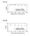
- FIG. 9 shows an experimental result when a real waveform is used.
- FIG. 9 shows measured jitter values for various numbers of sampling points per period T 0 .
- a peak-to-peak value of period jitter is especially over estimated as the over-sampling ratio is getting smaller.
- a peak-to-peak value of period jitter can be obtained correctly, by using the above correction term.
- the over-sampling ratio is small, its effect becomes large. For example, in the example shown in FIG.
- the error can be corrected by 8% in the case of 8 points per period (over-sampling ratio is 4), and by 18% in the case of 3 points per period (over-sampling ratio is 1.5).
- it has become possible to obtain a period jitter up to the case where the over-sampling ratio is 1.5 using the ⁇ method. This means that, if the sampling period is the same, a jitter of a signal under measurement having higher frequency can be measured more accurately.
- an RMS value J RMS and a peak-to-peak value J PP of the period jitter can be obtained by the following equations, respectively.
- J p ⁇ ⁇ p max k ⁇ ( J ⁇ [ k ] ) - min k ⁇ ( J ⁇ [ k ] ) ⁇ [ sec ] ( 8 )
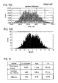
- FIG. 10 shows a histogram ( FIG. 10B ) of the period jitter measured by the corrected ⁇ method and a histogram ( FIG. 10A ) measured by the conventional time interval analyzer.
- FIG. 11 shows an RMS value and a peak-to-peak value of the period jitter measured by the corrected ⁇ method.
- the corrected ⁇ method provides both measured peak-to-peak and RMS jitter values that are comparable to the time interval analyzer method.
- the ⁇ method can measure a cycle-to-cycle period jitter and a period jitter simultaneously.
- a cycle-to-cycle period jitter J CC is a period fluctuation between adjacent clock cycles, and is expressed by an equation (9).
- J CC , PP max k ⁇ ( J CC ⁇ [ k ] ) - min k ⁇ ( J CC ⁇ [ k ] ) ⁇ [ sec ] ( 11 )
- L is the number of samples of the measured cycle-to-cycle period jitter data.
- FIG. 1 is a diagram showing a period jitter measurement using a conventional time interval analyzer
- FIG. 2 is a diagram showing a histogram of the measured values
- FIG. 3 is a diagram showing a jitter measurement using a conventional digital oscilloscope
- FIG. 4 is a diagram showing a configuration of a jitter measurement part in FIG. 3 ;
- FIG. 5A is a diagram showing a waveform of a signal under measurement
- FIG. 5B is a diagram showing measured period jitter of the signal under measurement
- FIG. 6 is a diagram showing a functional configuration of a jitter measurement apparatus based on the ⁇ method previously proposed by the inventors of the present invention.
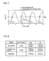
- FIG. 7 is a diagram showing a discrepancy between a zero-crossing point and an approximated zero-crossing point
- FIG. 8 is a diagram showing a comparison of measured root-mean-square values and peak-to-peak values of period jitter between the ⁇ method and the method by which the period jitter is corrected (the method of the present invention);
- FIG. 9A is a diagram showing an example of the effect of a correction term for an RMS period jitter estimation
- FIG. 9B is a diagram showing an example of the effect of a correction term for a peak-to-peak period jitter estimation
- FIG. 10A is a diagram showing a histogram of period jitter measured by the conventional time interval analyzer method
- FIG. 10B is a diagram showing a histogram of period jitter measured by the Corrected ⁇ method according to the present invention.
- FIG. 11 is a diagram showing RMS values and peak-to-peak values of period jitter measured by the time interval analyzer method and the Corrected ⁇ method;
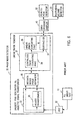
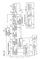
- FIG. 12 is a block diagram showing a functional configuration of an embodiment of the present invention.
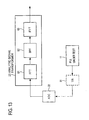
- FIG. 13 is a diagram showing a functional configuration of a partially modified example of the present invention.
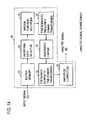
- FIG. 14 is a diagram showing another specific functional configuration of the analytic signal transforming part 23 ;
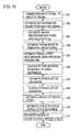
- FIG. 15 is a flow-chart showing a procedure of an embodiment of a method according to the present invention.
- FIG. 16 is a block diagram showing a portion of another embodiment of the apparatus according to the present invention.
- FIG. 17 is a flow-chart showing a portion of another embodiment of a method according to the present invention.
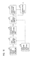
- FIG. 12 shows an embodiment of the present invention. Portions in FIG. 12 corresponding to those in FIG. 6 have the same reference numbers affixed thereto as those in FIG. 6 , and duplicated explanations for those portions will be omitted.
- a signal under measurement x c (t) is inputted to a timing jitter estimator 39 , and a timing jitter sequence of the inputted signal under measurement is obtained.
- an instantaneous phase noise waveform ⁇ (t) obtained from a linear phase remover 27 is sampled by a zero-crossing sampler 43 at timings closest to zero-crossing points of a real part x c (t) of an analytic signal z c (t) to obtain a timing jitter sequence. For this reason, a real part x c (t) of an analytic signal from an analytic signal transforming part 23 is inputted to a zero-crossing point detecting part 45 .
- the zero-crossing point detecting part 45 the maximum value of a waveform of an inputted real part x c (t) is defined as 100% level, and the minimum value is defined as 0% level to calculate 50% level V (50%) of the difference between the 100% level and the 0% level as a zero-crossing level.
- a difference between a sample value and 50% level V (50%) and a difference between its adjacent sample value and 50% level V (50%), i.e., (x c (j ⁇ 1) ⁇ V (50%)) and (x c (j) ⁇ V (50%)) are calculated, and further a product of those difference values (x c (j ⁇ 1) ⁇ V(50%)) ⁇ (x c (j) ⁇ V (50%)) is calculated.
- the sign of its sample value x c (j ⁇ 1) ⁇ V(50%) or x c (j) ⁇ V(50%) changes from a negative sign to a positive sign or from a positive sign to a negative sign.
- a sample value sequence outputted from the zero-crossing sampler 43 namely a timing jitter sequence
- a difference calculating part 46 where a difference sequence of the timing jitter sequence is calculated. That is, the equation (4) is calculated with respect to the inputted ⁇ [k] and ⁇ [k+1], and upon every update of k, the equation (4) is calculated to estimate a period jitter sequence.
- a timing sequence t[k] at each sampling time in the zero-crossing sampler 43 is inputted to a zero-crossing interval calculating part 47 , where a time interval T k,k+1 between approximated zero-crossing points is obtained through a calculation of the equation (6).
- an instantaneous linear phase from the linear phase remover 27 namely a linear phase component from the linear phase estimating part 29 in FIG. 6 is inputted to a fundamental period estimating part 48 , where a fundamental period T 0 is obtained from the inclination 2 ⁇ /T 0 of the instantaneous linear phase.
- This fundamental period T 0 may be obtained from the signal under measurement itself by inputting the signal under measurement from the AD converter 22 to the fundamental period estimating part 48 .
- that value T 0 may be stored in advance in the fundamental period estimating part 48 .
- a period jitter sequence from a difference calculating part 46 , an approximated zero-crossing point interval T k,k+1 from the zero-crossing interval calculating part 47 , and a fundamental period T 0 from the fundamental period estimating part 48 are inputted to a corrector part 49 , where each period jitter in the period jitter sequence is multiplied by T 0 /T k,k+1 , namely the equation (5) is calculated to obtain a corrected period jitter sequence.
- This corrected period jitter sequence is directly supplied to a cycle-to-cycle period jitter estimating part 52 , and at the same time, a period jitter sequence that is the corrected period jitter sequence delayed by its one element (one period jitter) is also supplied to the cycle-to-cycle period jitter estimating part 52 .
- the cycle-to-cycle period jitter estimating part (differentiator) 52 calculates a difference sequence of the period jitter sequence at each time point k using the equation (9) to obtain a cycle-to-cycle period jitter sequence.
- This embodiment is a case where the corrected period jitter sequence from the correcting part 49 and the cycle-to-cycle jitter period jitter sequence are switched by a switch 53 so that one of those corrected period jitter sequence and the cycle-to-cycle jitter period jitter sequence can selectively be supplied to a jitter detecting part 54 .
- a peak-to-peak detecting part 32 for obtaining a difference between the maximum value and the minimum value of the inputted jitter sequence
- an RMS detecting part 33 for calculating a root-mean-square (RMS) value of the inputted jitter sequence
- a histogram estimating part 18 for obtaining a histogram of the inputted jitter sequence.
- the corrected period jitter sequence is inputted to the jitter detecting part 54 .
- the equation (8) is calculated with respect to the period jitter sequence by the peak-to-peak detecting part 32 to obtain a peak-to-peak value J PP of period jitter
- the equation (7) is calculated by the RMS detecting part 33 to obtain an RMS value J RMS of period jitter
- a histogram of period jitter is obtained by the histogram estimating part 18 , and then those obtained values are outputted to be displayed on, for example, a display part (not shown).
- the cycle-to-cycle period jitter sequence is inputted to the jitter detecting part 54 .
- the equation (11) is calculated by the peak-to-peak detecting part 32 to obtain a peak-to-peak value J cc,pp of cycle-to-cycle period jitter
- the equation (10) is calculated by the RMS detecting part 33 to obtain an RMS value J CC,RMS of cycle-to-cycle period jitter
- a histogram of cycle-to-cycle period jitter is estimated by the histogram estimating part 18 . Then those obtained values are also outputted and are displayed on the display part if necessary.
- the cycle-to-cycle period jitter estimating part 52 and the switch 53 may be omitted to supply the corrected period jitter sequence from the correcting part 49 directly to the jitter detecting part 54 .
- the switch 53 may be omitted to supply the cycle-to-cycle period jitter sequence from the cycle-to-cycle period jitter estimating part 52 directly to the jitter detecting part 54 .
- the jitter detecting part 54 may only include any one or two of the peak-to-peak detecting part 32 , the RMS detecting part 33 , and the histogram estimating part 18 . In order to detect approximated zero-crossing points for sampling the instantaneous phase noise ⁇ (t), not only the real part signal is utilized but also the signal under measurement itself or its fundamental wave component may be utilized.
- a clock signal from the PLL under test 11 can be supplied to the AD converter 22 via a waveform clipper 56 to make amplitude of the clock signal constant.
- a jitter can accurately be measured in the state that the phase noise waveform ⁇ (t) is not influenced by amplitude modulation components.
- This process for removing amplitude modulation components from the input signal may be performed at the output side of the AD converter 22 .
- a process of an analytic signal transforming part 23 for transforming an input signal to an analytic signal z c (t) comprises the steps of transforming a digital input signal from the AD converter 22 into a both-sided spectrum signal in frequency domain using, for example, Fast Fourier Transform (FFT) by the time domain to the frequency domain transforming part 61 , making negative frequency components of the both-sided spectra zeros by a bandpass filter 62 , with passing frequency components around a positive fundamental frequency of the input clock signal. If necessary, the level of the extracted frequency components is doubled to compensate the energy of the cut off negative frequency components.
- An output of the bandpass filter 62 is inverse-transformed into the time domain using, for example, Inverse Fast Fourier Transform (IFFT) by the frequency domain to the time domain transforming part 63 to obtain an analytic signal z c (t).
- IFFT Inverse Fast Fourier Transform
- a digitized input signal is stored in a buffer memory 71 .
- a portion of the signal stored in the buffer memory 71 is taken out therefrom by a signal sectioning part 72 in the sequential order such that the current signal section and previous signal section are overlapped with each other.
- the signal section is multiplied by a window function multiplying part 73 , and an output signal of the window function multiplying part 73 is transformed into a both-sided spectrum signal in frequency domain using Fast Fourier Transform by the time domain to the frequency domain transforming part 74 .
- Negative frequency components of this spectrum signal are made zeros to obtain a single-sided spectrum signal.
- components around a fundamental frequency of the input signal are retained and the other frequency components are made zeros by a bandwidth limiting part 75 .
- This band-limited signal is transformed into the time domain by the frequency domain to the time domain transforming part 76 using Inverse FFT. Then this transformed signal in time domain is multiplied by an inverse window function by an amplitude correction part 77 to obtain an analytic signal.
- the input frequency range of the present invention can be extended by using a frequency divider 81 , as illustrated by dashed lines in FIG. 13 .
- the frequency-divided clock signal may be supplied to the analytic signal transforming part 23 .
- the clock signal (signal under measurement) may be converted into a signal with difference frequency between those signals to supply the signal to the analytic signal transforming part 23 .
- a low frequency component removing part 82 can be inserted into the output side of the linear phase removing part 27 in series so that low frequency components of the instantaneous phase noise ⁇ (t) are removed therefrom, and the instantaneous phase noise ⁇ (t) is supplied to the zero-crossing sampler 43 .
- FIG. 15 shows a flow-chart of the embodiment. This is, an example of the measuring method using the apparatus shown in FIG. 12 .
- the input signal (signal under measurement) is transformed into a band-limited analytic signal by the analytic signal transforming part 23 .
- an instantaneous phase of the input signal is estimated using the analytic signal by the instantaneous phase estimating part 26 , and then in step 203 , a linear instantaneous phase corresponding to an ideal clock signal is estimated from this instantaneous phase by the linear phase estimating part 29 (FIG.
- step 204 a linear phase component is removed from the instantaneous phase by the linear phase removing part 27 to estimate an instantaneous phase noise ⁇ (t) of the input signal.
- step 205 data of the instantaneous phase noise ⁇ (t) close to zero-crossing timings of a real part of the analytic signal are sampled by the zero-crossing sampler 43 to estimate a timing jitter sequence of the input signal.
- step 206 a difference between approximated zero-crossing points from the zero-crossing point estimating part 45 is calculated by the zero-crossing interval calculating part 47 to estimate a zero-crossing time interval sequence.
- a difference sequence of the timing jitter sequence is calculated by the differentiator 46 to estimate a period jitter sequence of the signal under measurement.
- the period jitter sequence is multiplied by a ratio of the fundamental period T 0 and the zero-crossing time interval T k,k+1 by the corrector part 49 to correct the difference-based period jitter sequence.
- a period jitter of the signal under measurement is obtained by the jitter detecting part 54 from the corrected period jitter sequence.
- step 209 the peak-to-peak detecting part 32 obtains a peak-to-peak value J pp of period jitter using the equation (8), the RMS detecting part 33 obtains an RMS value J RMS of period jitter using the equation (7), and the histogram estimating part 18 obtains a histogram from the period jitter sequence.
- step 210 in the state that the switch 53 is connected to the cycle-to-cycle period jitter estimating part 52 , a difference sequence of the corrected period jitter sequence is calculated by the cycle-to-cycle period jitter estimating part 52 to obtain a cycle-to-cycle period jitter sequence of the signal under measurement.
- step 211 a cycle-to-cycle period jitter of the signal under measurement is obtained by the jitter detecting part 54 from the cycle-to-cycle period jitter sequence.
- the peak-to-peak detecting part 32 obtains a peak-to-peak value J cc,pp of cycle-to-cycle period jitter using the equation (11)
- the RMS detecting part 33 obtains an RMS value J CC,RMS of cycle-to-cycle period jitter using the equation (10)
- the histogram estimating part 18 obtains a histogram of the cycle-to-cycle period jitter.
- the estimation of the fundamental period T 0 in the step 203 and the calculation of the zero-crossing time interval T k,k+1 in step 206 may be performed before the correction in the step 208 , and therefore the sequence of those processes is not limited to that of the example described above.
- the estimation of the fundamental period T 0 may be obtained directly from the signal under measurement.
- the steps 210 and 211 may be omitted.
- the step 209 may be omitted.
- any one or two of the peak-to-peak value, the RMS value, and the histogram may only be obtained.
- a clock signal of a microprocessor is mainly discussed as a signal under measurement (input signal).
- the present invention can be applied to a measurement of period jitter and/or cycle-to-cycle period jitter of a clock signal used in another equipment, or of a periodic signal such as sine wave or the like generated by another equipment.
- the input signal may be processed in the analog signal form rather than immediately converting it to a digital signal using the AD converter, and thereafter the signal may be converted, in an appropriate processing stage, to a digital signal.
- the apparatus shown in FIG. 12 may also be functioned by executing a program in a computer.
- an instantaneous phase noise ⁇ (t) is sampled at approximated zero-crossing points to obtain a timing jitter sequence ⁇ [n].
- the sampling process at the approximated zero-crossing points may be inserted in series, for example as indicated by dashed lines in FIG. 16 , between the instantaneous phase estimating part 26 and the continuous phase converting part 28 .
- the sampling process at the approximated zero-crossing points may be inserted in series between the continuous phase converting part 28 and the linear phase estimator 29 /subtractor 31 .
- the timing jitter sequence ⁇ [n] can also be obtained from the subtractor 31 .
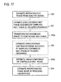
- the estimation of the instantaneous phase noise ⁇ (t) from an instantaneous phase is performed by the configuration of the linear phase remover 27 shown in FIG. 6 . Therefore, the processing procedure is, as shown in FIG. 17 , that after an instantaneous phase is obtained in the step 202 in FIG. 15 , the instantaneous phase is transformed to a continuous phase by the continuous phase converting part 28 in step 203 a , an instantaneous linear phase of the continuous phase is estimated by the linear phase estimator 29 in step 203 b , and thereafter in step 204 , the instantaneous linear phase is removed from the continuous instantaneous phase by the subtractor 31 to obtain an instantaneous noise phase ⁇ (t).
- step 202 approximated zero-crossing samplings may be applied to the instantaneous phase in step 301 to obtain a sample sequence of instantaneous phase, and then the process moves to step 203 a .
- the sample sequence may be transformed to a continuous instantaneous phase.
- the continuous instantaneous phase obtained in the step 203 a may be sampled at approximated zero-crossing points to obtain a sample sequence of continuous instantaneous phase, and then the process moves to step 203 b .
- an instantaneous linear phase may be estimated from the sample sequence of continuous instantaneous phase.
- a timing jitter sequence ⁇ [n] that is produced by sampling the instantaneous phase noise at approximated zero-crossing points.
- estimation errors caused by the sampling at approximated zero-crossing points can be decreased, a measurement result compatible with the conventional time interval analyzer method can be obtained, and in addition, the measurement can be performed in short time compared with the conventional time interval analyzer method.
Abstract
Description
x c(t)=A ccos(2πf c t+θ c−Δφ(t))
The Ac and the fc are nominal values of amplitude and frequency of a clock signal respectively, the θc is an initial phase angle, and the Δφ(t) is a phase fluctuation that is called an instantaneous phase noise.
{circumflex over (X)} c(t)=H[X c(t)]=A csin(2πf c t+θ c−Δθ(t))
Then, an analytic signal zc(t) having xc(t) and {circumflex over (x)}c(t) as a real part and an imaginary part, respectively, is obtained as follows.
Θ(t)=[2πf c t+θ c−Δφ(t)]mod 2π[rad]
A linear phase is removed from this instantaneous phase Θ(t) by a
θ(t)=2πf c t+θ c−Δφ(t)[rad]
The phase unwrap method is shown in “A New Phase Unwrapping Algorithm” by Jose M. Tribolet, IEEE Trans. Acoust., Speech, Signal Processing, vol. ASSP-25, pp. 170-177, 1977 and in “On Frequency-Domain and Time-Domain Phase Unwrapping” by Kuno P. Zimmermann, Proc. IEEE. vol. 75, pp. 519-520, 1987.
θ(t)=Δφ(t)
The instantaneous phase noise waveform Δφ(t) thus obtained is inputted, after having been sampled by the zero-crossing sampler 34, to a peak-to-
In addition, the timing jitter sequence Δφ[n] is also inputted to a root-mean-
In this case, f0 is a fundamental frequency of the signal under measurement, and is equal to f0=1/T0 where T0 is a fundamental period of the signal under measurement. An instantaneous frequency of z(t) is expressed by the following equation.
Therefore, the following equation is given.
A timing jitter sequence is obtained by sampling an instantaneous phase noise waveform Δφ(t) at a timing (referred to as an approximated zero-crossing point) closest to each zero-crossing point of a real part x(t) of an analytic signal z(t), and then it is assumed that the sampling interval Tk,k+1 of the approximated zero-crossing points is equal to a fundamental period T0. In this case, a period jitter J is obtained, as shown by the following equation, as a difference sequence of a timing jitter sequence.
where the term, T0/Tk,k+1 corrects the instantaneous phase noise difference using the difference-based approximation (equation (4)). A period jitter can be obtained with high accuracy using this correction term. As shown in
T k,k+1 =t[k+1]−t[k][sec] (6)
Therefore, by obtaining differences between the period jitter data measured as described above and then calculating their root-mean-square and a difference between the maximum value and the minimum value, an RMS value JCC,RMS and a peak-to-peak value JCC,PP of cycle-to-cycle period jitter can be obtained by equations (10) and (11), respectively.
Claims (14)
Priority Applications (4)
| Application Number | Priority Date | Filing Date | Title |
|---|---|---|---|
| US09/811,153 US6922439B2 (en) | 2001-03-16 | 2001-03-16 | Apparatus for and method of measuring jitter |
| PCT/JP2002/002163 WO2002076008A2 (en) | 2001-03-16 | 2002-03-08 | Apparatus for and method of measuring jitter |
| JP2002573360A JP3974040B2 (en) | 2001-03-16 | 2002-03-08 | Jitter measuring apparatus and jitter measuring method |
| DE10291162T DE10291162B4 (en) | 2001-03-16 | 2002-03-08 | Method for measuring trembling |
Applications Claiming Priority (1)
| Application Number | Priority Date | Filing Date | Title |
|---|---|---|---|
| US09/811,153 US6922439B2 (en) | 2001-03-16 | 2001-03-16 | Apparatus for and method of measuring jitter |
Publications (2)
| Publication Number | Publication Date |
|---|---|
| US20020163958A1 US20020163958A1 (en) | 2002-11-07 |
| US6922439B2 true US6922439B2 (en) | 2005-07-26 |
Family
ID=25205714
Family Applications (1)
| Application Number | Title | Priority Date | Filing Date |
|---|---|---|---|
| US09/811,153 Expired - Lifetime US6922439B2 (en) | 2001-03-16 | 2001-03-16 | Apparatus for and method of measuring jitter |
Country Status (4)
| Country | Link |
|---|---|
| US (1) | US6922439B2 (en) |
| JP (1) | JP3974040B2 (en) |
| DE (1) | DE10291162B4 (en) |
| WO (1) | WO2002076008A2 (en) |
Cited By (18)
| Publication number | Priority date | Publication date | Assignee | Title |
|---|---|---|---|---|
| US20020158619A1 (en) * | 2001-04-27 | 2002-10-31 | Chen Ernest C. | Satellite TWTA on-line non-linearity measurement |
| US20040091033A1 (en) * | 2002-10-25 | 2004-05-13 | Chen Emest C. | On-line phase noise measurement for layered modulation |
| US20050185708A1 (en) * | 2004-02-18 | 2005-08-25 | Advantest Corporation | Apparatus for measuring jitter, method of measuring jitter and computer-readable medium storing a program thereof |
| US20060013333A1 (en) * | 2001-04-27 | 2006-01-19 | The Directv Group, Inc. | Maximizing power and spectral efficiencies for layered and conventional modulations |
| US20060056541A1 (en) * | 2002-07-01 | 2006-03-16 | Chen Ernest C | Improving hierarchical 8psk performance |
| US20060153315A1 (en) * | 2001-04-27 | 2006-07-13 | Chen Ernest C | Lower complexity layered modulation signal processor |
| US20060251162A1 (en) * | 2005-05-04 | 2006-11-09 | Advantest Corporation | Apparatus for measuring jitter and method of measuring jitter |
| US20070116156A1 (en) * | 2001-04-27 | 2007-05-24 | Chen Ernest C | Layered modulation for digital signals |
| US20070140306A1 (en) * | 2005-12-16 | 2007-06-21 | International Business Machines Corporation | Identifying existence and rate of jitter during real-time audio and video streaming |
| US20080279268A1 (en) * | 2007-05-10 | 2008-11-13 | Agilent Technologies, Inc. | Method for measuring noise, apparatus for measuring noise, and program for measuring noise |
| US20080301509A1 (en) * | 2007-05-31 | 2008-12-04 | Kingtiger Technology (Canada) Inc. | Method and apparatus for testing integrated circuits by employing test vector patterns that satisfy passband requirements imposed by communication channels |
| US7738587B2 (en) | 2002-07-03 | 2010-06-15 | The Directv Group, Inc. | Method and apparatus for layered modulation |
| CN101833036A (en) * | 2010-04-15 | 2010-09-15 | 南京邮电大学 | Method for measuring instantaneous phase of alternating current |
| US7822154B2 (en) | 2001-04-27 | 2010-10-26 | The Directv Group, Inc. | Signal, interference and noise power measurement |
| US8005035B2 (en) | 2001-04-27 | 2011-08-23 | The Directv Group, Inc. | Online output multiplexer filter measurement |
| US8073042B1 (en) * | 2005-04-13 | 2011-12-06 | Cypress Semiconductor Corporation | Recursive range controller |
| US8189728B1 (en) * | 2006-08-22 | 2012-05-29 | Marvell International Ltd. | Jitter measurement |
| US8259641B2 (en) | 2001-04-27 | 2012-09-04 | The Directv Group, Inc. | Feeder link configurations to support layered modulation for digital signals |
Families Citing this family (5)
| Publication number | Priority date | Publication date | Assignee | Title |
|---|---|---|---|---|
| US7339985B2 (en) * | 2003-01-08 | 2008-03-04 | National Instruments Corporation | Zero crossing method of symbol rate and timing estimation |
| US7778315B2 (en) * | 2004-04-14 | 2010-08-17 | Tektronix, Inc. | Measuring instantaneous signal dependent nonlinear distortion in response to varying frequency sinusoidal test signal |
| US7912117B2 (en) * | 2006-09-28 | 2011-03-22 | Tektronix, Inc. | Transport delay and jitter measurements |
| JP2009250644A (en) * | 2008-04-02 | 2009-10-29 | Nippon Telegr & Teleph Corp <Ntt> | Jitter detection circuit |
| US20180328764A1 (en) * | 2017-05-11 | 2018-11-15 | Craig Alan D'Ambrosio | Method of Analyzing Signal Quality in Order to Determine the Operational Characteristics of a Measuring Device |
Citations (4)
| Publication number | Priority date | Publication date | Assignee | Title |
|---|---|---|---|---|
| US5923706A (en) * | 1994-07-21 | 1999-07-13 | Tektronix, Inc. | Process for measuring phase jitter of a data signal |
| US6240130B1 (en) * | 1997-07-30 | 2001-05-29 | Texas Instruments Incorporated | Method and apparatus to measure jitter. |
| US6295315B1 (en) * | 1999-04-20 | 2001-09-25 | Arnold M. Frisch | Jitter measurement system and method |
| US6377644B1 (en) * | 1998-03-09 | 2002-04-23 | Stmicroelectronics S.A. | Periodic signal digital testing |
-
2001
- 2001-03-16 US US09/811,153 patent/US6922439B2/en not_active Expired - Lifetime
-
2002
- 2002-03-08 WO PCT/JP2002/002163 patent/WO2002076008A2/en active Application Filing
- 2002-03-08 JP JP2002573360A patent/JP3974040B2/en not_active Expired - Fee Related
- 2002-03-08 DE DE10291162T patent/DE10291162B4/en not_active Expired - Fee Related
Patent Citations (4)
| Publication number | Priority date | Publication date | Assignee | Title |
|---|---|---|---|---|
| US5923706A (en) * | 1994-07-21 | 1999-07-13 | Tektronix, Inc. | Process for measuring phase jitter of a data signal |
| US6240130B1 (en) * | 1997-07-30 | 2001-05-29 | Texas Instruments Incorporated | Method and apparatus to measure jitter. |
| US6377644B1 (en) * | 1998-03-09 | 2002-04-23 | Stmicroelectronics S.A. | Periodic signal digital testing |
| US6295315B1 (en) * | 1999-04-20 | 2001-09-25 | Arnold M. Frisch | Jitter measurement system and method |
Non-Patent Citations (1)
| Title |
|---|
| Yamaguchi, T., et al., "Extraction of peak-to-peak and RMS sinusoidal jitter using an analytic signal method," Proceedings 18th IEEE VLSI Test Symposium, Montreal, Quebec, Canada, Apr. 30-May 4, 2000, pp. 395-402. |
Cited By (25)
| Publication number | Priority date | Publication date | Assignee | Title |
|---|---|---|---|---|
| US20020158619A1 (en) * | 2001-04-27 | 2002-10-31 | Chen Ernest C. | Satellite TWTA on-line non-linearity measurement |
| US8259641B2 (en) | 2001-04-27 | 2012-09-04 | The Directv Group, Inc. | Feeder link configurations to support layered modulation for digital signals |
| US8005035B2 (en) | 2001-04-27 | 2011-08-23 | The Directv Group, Inc. | Online output multiplexer filter measurement |
| US20060013333A1 (en) * | 2001-04-27 | 2006-01-19 | The Directv Group, Inc. | Maximizing power and spectral efficiencies for layered and conventional modulations |
| US20060153315A1 (en) * | 2001-04-27 | 2006-07-13 | Chen Ernest C | Lower complexity layered modulation signal processor |
| US7920643B2 (en) | 2001-04-27 | 2011-04-05 | The Directv Group, Inc. | Maximizing power and spectral efficiencies for layered and conventional modulations |
| US20070116156A1 (en) * | 2001-04-27 | 2007-05-24 | Chen Ernest C | Layered modulation for digital signals |
| US7822154B2 (en) | 2001-04-27 | 2010-10-26 | The Directv Group, Inc. | Signal, interference and noise power measurement |
| US7778365B2 (en) | 2001-04-27 | 2010-08-17 | The Directv Group, Inc. | Satellite TWTA on-line non-linearity measurement |
| US7706466B2 (en) | 2001-04-27 | 2010-04-27 | The Directv Group, Inc. | Lower complexity layered modulation signal processor |
| US20060056541A1 (en) * | 2002-07-01 | 2006-03-16 | Chen Ernest C | Improving hierarchical 8psk performance |
| US7738587B2 (en) | 2002-07-03 | 2010-06-15 | The Directv Group, Inc. | Method and apparatus for layered modulation |
| US7463676B2 (en) * | 2002-10-25 | 2008-12-09 | The Directv Group, Inc. | On-line phase noise measurement for layered modulation |
| US20040091033A1 (en) * | 2002-10-25 | 2004-05-13 | Chen Emest C. | On-line phase noise measurement for layered modulation |
| US20050185708A1 (en) * | 2004-02-18 | 2005-08-25 | Advantest Corporation | Apparatus for measuring jitter, method of measuring jitter and computer-readable medium storing a program thereof |
| US8073042B1 (en) * | 2005-04-13 | 2011-12-06 | Cypress Semiconductor Corporation | Recursive range controller |
| US8526558B1 (en) | 2005-04-13 | 2013-09-03 | Cypress Semiconductor Corporation | Recursive range controller |
| US7460592B2 (en) * | 2005-05-04 | 2008-12-02 | Advantest Corporation | Apparatus for measuring jitter and method of measuring jitter |
| US20060251162A1 (en) * | 2005-05-04 | 2006-11-09 | Advantest Corporation | Apparatus for measuring jitter and method of measuring jitter |
| US20070140306A1 (en) * | 2005-12-16 | 2007-06-21 | International Business Machines Corporation | Identifying existence and rate of jitter during real-time audio and video streaming |
| US8189728B1 (en) * | 2006-08-22 | 2012-05-29 | Marvell International Ltd. | Jitter measurement |
| US20080279268A1 (en) * | 2007-05-10 | 2008-11-13 | Agilent Technologies, Inc. | Method for measuring noise, apparatus for measuring noise, and program for measuring noise |
| US7620861B2 (en) | 2007-05-31 | 2009-11-17 | Kingtiger Technology (Canada) Inc. | Method and apparatus for testing integrated circuits by employing test vector patterns that satisfy passband requirements imposed by communication channels |
| US20080301509A1 (en) * | 2007-05-31 | 2008-12-04 | Kingtiger Technology (Canada) Inc. | Method and apparatus for testing integrated circuits by employing test vector patterns that satisfy passband requirements imposed by communication channels |
| CN101833036A (en) * | 2010-04-15 | 2010-09-15 | 南京邮电大学 | Method for measuring instantaneous phase of alternating current |
Also Published As
| Publication number | Publication date |
|---|---|
| JP3974040B2 (en) | 2007-09-12 |
| JP2004519678A (en) | 2004-07-02 |
| US20020163958A1 (en) | 2002-11-07 |
| WO2002076008A2 (en) | 2002-09-26 |
| DE10291162T1 (en) | 2003-09-04 |
| WO2002076008A3 (en) | 2002-12-12 |
| DE10291162B4 (en) | 2008-11-27 |
Similar Documents
| Publication | Publication Date | Title |
|---|---|---|
| US6922439B2 (en) | Apparatus for and method of measuring jitter | |
| US6460001B1 (en) | Apparatus for and method of measuring a peak jitter | |
| JP5218783B2 (en) | Real-time spectrum trigger generator | |
| US7856330B2 (en) | Measuring apparatus, testing apparatus, and electronic device | |
| US7305025B2 (en) | Measurement instrument and measurement method | |
| US6594595B2 (en) | Apparatus for and method of measuring cross-correlation coefficient between signals | |
| US7127018B2 (en) | Apparatus for and method of measuring clock skew | |
| US7636387B2 (en) | Measuring apparatus and measuring method | |
| US7317309B2 (en) | Wideband signal analyzing apparatus, wideband period jitter analyzing apparatus, and wideband skew analyzing apparatus | |
| US6598004B1 (en) | Jitter measurement apparatus and its method | |
| US6735538B1 (en) | Apparatus and method for measuring quality measure of phase noise waveform | |
| US7203229B1 (en) | Apparatus for and method of measuring jitter | |
| US20090234604A1 (en) | Measuring device, test device, electronic device, program, and recording medium | |
| US20050185708A1 (en) | Apparatus for measuring jitter, method of measuring jitter and computer-readable medium storing a program thereof | |
| US6737852B2 (en) | Clock skew measuring apparatus and method | |
| US6525523B1 (en) | Jitter measurement apparatus and its method | |
| US7263150B2 (en) | Probability estimating apparatus and method for peak-to-peak clock skews | |
| US6775321B1 (en) | Apparatus for and method of measuring a jitter | |
| US10534018B1 (en) | Time base correction method for high accuracy sampling scope-based measurements | |
| Stenbakken et al. | Timebase distortion measurements using multiphase sinewaves | |
| US20030101010A1 (en) | Low distortion frequency tracking technique | |
| JPH0356892A (en) | Method and device for sample time measurement |
Legal Events
| Date | Code | Title | Description |
|---|---|---|---|
| AS | Assignment |
Owner name: ADVANTEST CORPORATION, JAPAN Free format text: ASSIGNMENT OF ASSIGNORS INTEREST;ASSIGNORS:YAMAGUCHI, TAKAHIRO;ISHIDA, MASAHIRO;REEL/FRAME:012018/0463 Effective date: 20010628 |
|
| STCF | Information on status: patent grant |
Free format text: PATENTED CASE |
|
| FEPP | Fee payment procedure |
Free format text: PAYOR NUMBER ASSIGNED (ORIGINAL EVENT CODE: ASPN); ENTITY STATUS OF PATENT OWNER: LARGE ENTITY |
|
| FPAY | Fee payment |
Year of fee payment: 4 |
|
| FPAY | Fee payment |
Year of fee payment: 8 |
|
| FPAY | Fee payment |
Year of fee payment: 12 |
|
| AS | Assignment |
Owner name: ADVANTEST CORPORATION, JAPAN Free format text: CHANGE OF ADDRESS;ASSIGNOR:ADVANTEST CORPORATION;REEL/FRAME:047987/0626 Effective date: 20181112 |