EP1546605B1 - Projecteur - Google Patents
Projecteur Download PDFInfo
- Publication number
- EP1546605B1 EP1546605B1 EP03720260A EP03720260A EP1546605B1 EP 1546605 B1 EP1546605 B1 EP 1546605B1 EP 03720260 A EP03720260 A EP 03720260A EP 03720260 A EP03720260 A EP 03720260A EP 1546605 B1 EP1546605 B1 EP 1546605B1
- Authority
- EP
- European Patent Office
- Prior art keywords
- housing
- spotlight
- ventilation
- wall
- ventilation shaft
- Prior art date
- Legal status (The legal status is an assumption and is not a legal conclusion. Google has not performed a legal analysis and makes no representation as to the accuracy of the status listed.)
- Expired - Lifetime
Links
- 238000009423 ventilation Methods 0.000 claims abstract description 71
- 238000001816 cooling Methods 0.000 claims description 25
- 238000005452 bending Methods 0.000 claims description 3
- 239000011358 absorbing material Substances 0.000 claims description 2
- 238000007493 shaping process Methods 0.000 claims description 2
- 230000005855 radiation Effects 0.000 description 7
- 241000446313 Lamella Species 0.000 description 5
- 230000017525 heat dissipation Effects 0.000 description 4
- 230000003287 optical effect Effects 0.000 description 4
- DGAQECJNVWCQMB-PUAWFVPOSA-M Ilexoside XXIX Chemical compound C[C@@H]1CC[C@@]2(CC[C@@]3(C(=CC[C@H]4[C@]3(CC[C@@H]5[C@@]4(CC[C@@H](C5(C)C)OS(=O)(=O)[O-])C)C)[C@@H]2[C@]1(C)O)C)C(=O)O[C@H]6[C@@H]([C@H]([C@@H]([C@H](O6)CO)O)O)O.[Na+] DGAQECJNVWCQMB-PUAWFVPOSA-M 0.000 description 1
- 238000009825 accumulation Methods 0.000 description 1
- 229910052782 aluminium Inorganic materials 0.000 description 1
- XAGFODPZIPBFFR-UHFFFAOYSA-N aluminium Chemical compound [Al] XAGFODPZIPBFFR-UHFFFAOYSA-N 0.000 description 1
- 230000004888 barrier function Effects 0.000 description 1
- 230000015572 biosynthetic process Effects 0.000 description 1
- 238000005266 casting Methods 0.000 description 1
- 238000010276 construction Methods 0.000 description 1
- 238000007599 discharging Methods 0.000 description 1
- 238000009826 distribution Methods 0.000 description 1
- 230000000694 effects Effects 0.000 description 1
- 239000011521 glass Substances 0.000 description 1
- 238000010438 heat treatment Methods 0.000 description 1
- 239000000463 material Substances 0.000 description 1
- 229910001507 metal halide Inorganic materials 0.000 description 1
- 150000005309 metal halides Chemical class 0.000 description 1
- 238000013021 overheating Methods 0.000 description 1
- 230000001681 protective effect Effects 0.000 description 1
- 229910052708 sodium Inorganic materials 0.000 description 1
- 239000011734 sodium Substances 0.000 description 1
- 230000003595 spectral effect Effects 0.000 description 1
- 238000009827 uniform distribution Methods 0.000 description 1
Images


Classifications
-
- F—MECHANICAL ENGINEERING; LIGHTING; HEATING; WEAPONS; BLASTING
- F21—LIGHTING
- F21V—FUNCTIONAL FEATURES OR DETAILS OF LIGHTING DEVICES OR SYSTEMS THEREOF; STRUCTURAL COMBINATIONS OF LIGHTING DEVICES WITH OTHER ARTICLES, NOT OTHERWISE PROVIDED FOR
- F21V29/00—Protecting lighting devices from thermal damage; Cooling or heating arrangements specially adapted for lighting devices or systems
- F21V29/50—Cooling arrangements
- F21V29/70—Cooling arrangements characterised by passive heat-dissipating elements, e.g. heat-sinks
- F21V29/83—Cooling arrangements characterised by passive heat-dissipating elements, e.g. heat-sinks the elements having apertures, ducts or channels, e.g. heat radiation holes
-
- F—MECHANICAL ENGINEERING; LIGHTING; HEATING; WEAPONS; BLASTING
- F21—LIGHTING
- F21W—INDEXING SCHEME ASSOCIATED WITH SUBCLASSES F21K, F21L, F21S and F21V, RELATING TO USES OR APPLICATIONS OF LIGHTING DEVICES OR SYSTEMS
- F21W2131/00—Use or application of lighting devices or systems not provided for in codes F21W2102/00-F21W2121/00
- F21W2131/40—Lighting for industrial, commercial, recreational or military use
- F21W2131/406—Lighting for industrial, commercial, recreational or military use for theatres, stages or film studios
Definitions
- the invention relates to a headlamp, in particular a web, studio, film or television headlamp according to the preamble of claim 1.
- Such headlamps have a arranged in a Schelwerfergepuruse one or two-capped light source, which consists of a lamp or a burner, for example a discharge lamp in the form of a metal halide lamp or a high-pressure sodium vapor lamp or the like and with the help of a also arranged in the headlight housing reflector emits the light in one direction from an opening of the spotlight housing.
- the spotlight housing On the front side, the spotlight housing is thereby closed to protect the light source and / or for modeling the emitted light with a preferably transparent cover element in the form of a protective pane or a lens held in a frame or a frame.
- a heat dissipation is therefore essentially possible only by a correspondingly enlarged surface of the existing example of aluminum castings and Alurninium extruded headlamp housing, which is effected by appropriate projecting from the contour of the headlight housing cooling fins.
- a correspondingly enlarged surface of the headlight housing also leads to an increase in the total headlamp and thus prevents a compact design of a headlamp, in particular a headlight of great power.
- a studio headlamp of the generic type which has a light source and a light source surrounding the headlight housing, which consists of a lower, substantially cuboid housing part and an upper, cylindrical housing part with a front, translucent cover. While the upper housing part has a profiled surface for better heat dissipation, a ventilation duct with ventilation ducts separated by lamellae is arranged in the lower housing part, which have a first lamellae section adjoining the air inlet openings and a second lamella section adjoining the air outlet openings, which faces the first lamella section is bent. This design of the slats, a light emission from the interior of the headlamp housing is avoided.
- a headlamp with a light source and a light source surrounding the headlight housing known, which consists of an upper, cylindrical housing part and a lower, cuboid housing part.
- the upper, cylindrical housing part is connected to a flat ventilation shaft with ventilation channels separated by lamellae and has an open double wall.
- the lower, cuboid housing part is provided at its sides and at the bottom with ventilation slots and contains in the interior opposite to the arranged on the side walls ventilation slots inclined more ventilation slots on an intermediate wall.
- a headlight housing with arranged on the housing walls ventilation ducts with separate ventilation ducts, which are separated by lamellae, so that there are uniform ventilation ducts, flows through the cooling air into the interior of the spotlight housing.
- Object of the present invention is to provide a headlamps also large light output with a compact design, which dissipates the emitted from the light source of the headlamp heat radiation without light emission to the environment of the headlamp outside the front and ensures a uniformly distributed over the cross-sectional area of the headlamp housing air flow, with which the various areas in the interior of the headlight housing are uniformly flowed through with cooling air.
- the solution according to the invention provides a headlamp which has an extremely compact design even with high light output and the associated high heat output of the light source of the headlamp and dissipates the heat radiation emitted by the light source without noise and unwanted light leakage from the headlight housing and a uniform over the cross-sectional area of the Headlamp housing distributed air flow ensured with the various areas inside the headlamp housing evenly flowed through with cooling air.
- the solution according to the invention is based on the consideration to dissipate the heat radiation emitted by the light source of the headlight by means of increased cooling air supply by convection.
- the slats are formed so that the Heilleitabrough of the underside of the headlight housing adjacent slat substantially horizontally following the second slat portion, while with increasing distance the lamellae from the underside of the headlight housing) is provided an increasingly stronger bend of the Heilleitabroughe the fins.
- the ventilation shaft can optionally be integrated into the housing wall of the headlight housing, inserted into an opening of a housing wall of the headlight housing or placed on an opening of the housing wall of the headlight housing and connected to the housing wall.
- the ventilation shaft may have an opening into one or more openings of the housing wall of the headlight housing air outlet opening and projecting from the housing wall of the headlight housing air inlet opening or inserted into the housing wall of the headlight housing such that the air inlet opening projects from the housing wall of the headlight housing and the air outlet opening into the interior of the Headlight housing protrudes or be integrated into the housing wall of the headlight housing such that the air inlet opening is substantially flush with the housing wall and the air outlet opening is arranged in the interior of the headlight housing.
- a combination of all three arrangements of the ventilation shaft for controlled and optimal heat dissipation from the interior of the headlight housing is suitable, with different construction and arrangement forms of the ventilation shaft can be used optimally for the different housing walls.
- the formation of multiple ventilation channels separated by lamellae enables, on the one hand, a controlled supply of cooling air to the individual areas in the interior of the headlight housing and, on the other hand, a highly effective light barrier, which blocks the escape of stray light from the interior of the headlight housing.
- This effect is enhanced by an appropriate selection of materials and color or shape of the slats, which in particular consist of black and a strong light-absorbing material.
- the fins are formed and arranged in the ventilation shaft so that the supplied via the ventilation duct cooling air in different areas in the interior of the headlight housing is effective.
- the fins are arranged at substantially equal distances from one another and to the wall of the ventilation shaft and have at least one bend or deflection within the ventilation shaft.
- headlight performance and design of the headlamp housing ventilation ducts can be arranged on both side walls and / or on the front and rear side wall and / or on the underside of the headlight housing.
- vent shaft When arranged at the bottom of the headlight housing vent shaft opens the air outlet opening in the immediate vicinity of the light source or the light source socket in the interior of the headlight housing.
- a ventilation duct a highly effective air flow is effected on the side surface of the light source in the interior of the headlight housing, wherein the cooling air is guided in a fan shape around the light source.
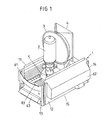
- Fig. 1 shows a perspective view of a part of a headlamp with a lower part of a headlight housing 1, in which a light source 2, which is inserted in a light source base 5 connected to the headlight housing 1, and a reflector 3, which is also attached to the reflector housing 1 with a reflector holder 4 is connected, are arranged. Trained as a lamp or burner light source 2, the reflector 3 and the reflector holder 4 are surrounded by a connected to the lower part of the headlight housing 1 upper, usually cylindrical headlight housing part, on the front side of a cover in the form of a glass or lens is arranged and its Cover element opposite end is completed.
- the upper headlight housing part is usually formed profiled to increase the heat-emitting surface.
- the lower headlight housing 1 is substantially cuboid and has two mutually parallel side walls 11, 12 a front and rear side wall 13, 14 and an underside 15. About several fasteners on the front and rear walls 13, 14 and the side walls 11, 12, the lower headlight housing 1 is connected to the upper headlight housing part, not shown.
- the headlight housing 1 has a plurality of ventilation shafts 61 to 63 and in Fig. 2 recognizable ventilation ducts 64, 65, is passed over the cooling air into the interior of the headlight housing 1.
- the cooling air passes through outside the headlight housing 1 arranged air inlet openings 71 to 73 ( Fig. 2 and 3 ) of the ventilation ducts 61 to 65 to open into the interior of the headlight housing 1 air outlet openings 81 to 83, of which in the perspective view according to Fig. 1 the air outlet opening 83 of one of the ventilation ducts can be seen.
- FIG. 2 illustrated longitudinal section through the headlight housing 1 according to Fig. 1 and in Fig. 3 illustrated cross section through the headlight housing 1 according to Fig. 1
- Fig. 3 illustrated cross section through the headlight housing 1 according to Fig. 1
- Fig. 2 shows a longitudinal section of the headlight housing 1, a front ventilation shaft 63 and rear ventilation shaft 64 and a arranged on the underside of the headlight housing 1 ventilation shaft 65th Der Front ventilation shaft 63 and the rear ventilation shaft 64 are inserted into the front wall 13 and rear wall 14 of the headlight housing 1 such that the air inlet openings 72 are arranged at an angle to the front wall 13 and rear wall 14 outside the surface of the front wall 13 and rear wall 14, while the Air outlet openings 82 are arranged in the interior of the headlight housing 1 and extend substantially parallel to the course of the front wall 13 and rear wall 14.
- ventilation shaft 65 is integrated into the underside 15 of the headlight housing 1, that the air inlet opening 73 of the ventilation shaft 65 is flush with the wall surface of the bottom 15, while the air outlet opening 83 projects into the interior of the headlight housing 1 and there is arranged adjacent to the light source 2.
- FIG. 3 shown cross section through the headlight housing 1 shows the arranged on the side walls 11, 12 of the headlight housing 1 ventilation ducts 61, 62, the air inlet openings 71 substantially perpendicular from the side walls 11, 12 protrude, while the air outlet openings 81 of the ventilation ducts 61, 62 at openings in the Side walls 11, 12 adjacent.
- the trapezoidal ventilation shafts 61, 62 may be formed as part of the side walls 11, 12 or may be fitted, plugged or connected to the side walls 11, 12 provided with an opening in a suitable manner, or connected to the side walls 11, 12 via screw or clip connections.
- the cuts through the headlight housing 1 according to the Fig. 2 and 3 are provided in the interior of the ventilation ducts 61 to 65 a plurality of mutually parallel slats 7, which are arranged at equal distances from each other and to the side walls of the ventilation ducts 61 to 65.
- the light-absorbing lamellae 7 are bent so that they have a first section 91 (FIG. Fig. 3 ) and a second section 92 adjoining the air outlet opening.
- the lamellae 9 protrude beyond the air outlet openings 81 and there a bent again air duct 94, 96 or one with the second section 92 aligned air duct 93, 95 form.
- Fig. 2 shows an air duct caused by the slats 9 in the front and rear ventilation duct 63, 64, which is directed so that the cooling air flow L3, L4 is uniformly staggered in the longitudinal direction of the headlight housing 1 in the interior thereof.
- the cooling air flow L3, L4 is uniformly staggered in the longitudinal direction of the headlight housing 1 in the interior thereof.
- the arranged on the bottom 15 of the headlight housing 1 ventilation shaft 65 includes fins 9, which open at an angle to the bottom 15 in the bottom 15 of the headlight housing 1, while they extend in the region of the air outlet opening substantially perpendicular to the bottom 15 of the headlight housing 1.
- a staggered air fan L5 is achieved in front of the light source 2, which directs the emitted from the light source 2 infrared radiation directly to the upper headlight housing part.
- the arranged on the side walls 11, 12 of the headlight housing 1 ventilation ducts 61, 62 have according to Fig. 3 a plurality of mutually parallel slats 9, the air inlet opening 71 adjacent portions 91 parallel to the side walls 11, 12 extend, while leading to the air outlet opening 81 portions 92 of the fins 9 obliquely to the side walls 11, 12 extend and at an angle of the top of the wall of the ventilation shaft 61, 62 are adjusted.
- the provided in the air outlet openings 81 shipsleitabitese 93, 94 of the fins 9 are also aligned so that an effective distribution of the cooling air flows L1, L2 is effected.
- the upper lamella has a section 93 aligned with the second section 92 of the lamella 9, while the lamellae underneath have a section kinked once again as an air guiding section which projects substantially perpendicularly from the cross-sectional surface of the air outlet opening 81.
- Registered air guide arrows L1, L2 of the cooling air illustrate the uniformly distributed over the cross-sectional area of the headlight housing 1 through this shape and arrangement of the fins 9 and ventilation shafts 61, 62 so that the different areas in the interior of the headlight housing 1 are uniformly flowed through with cooling air.
- Essential in the design and arrangement of the fins 9 in the ventilation ducts 61 to 65 is that no cascading of the ventilation channels 7 and thus increasing from bottom to top heating in the air outlet openings is provided, but on the separate ventilation ducts 7 to each area of the air outlet openings the ventilation ducts 61 to 65 is discharged from outside the headlight housing 1 introduced cooling air.
Landscapes
- Engineering & Computer Science (AREA)
- General Engineering & Computer Science (AREA)
- Non-Portable Lighting Devices Or Systems Thereof (AREA)
- Arrangement Of Elements, Cooling, Sealing, Or The Like Of Lighting Devices (AREA)
- Crystals, And After-Treatments Of Crystals (AREA)
Claims (12)
- Projecteur, en particulier projecteur de scène, de studio, de film et/ou de télévision, comprenant une source lumineuse (2) et un boîtier de projecteur (1) entourant la source lumineuse (2), constitué d'une partie de boîtier de projecteur inférieure conçue sous une forme essentiellement parallélépipédique rectangulaire et d'une partie de boîtier de projecteur supérieure de forme cylindrique présentant un élément de recouvrement transparent, un puits d'aération (61 à 65) sur au moins une paroi de boîtier (11 - 15) de la partie de boîtier de projecteur inférieure étant agencé avec des canaux d'aération (7) séparés les uns des autres, lesquels sont séparés par des lamelles (9) présentant à l'intérieur du puits d'aération (61 - 65) une première section de lamelle (91) adjacente aux ouvertures d'admission d'air (71 - 73) et une seconde section de lamelle (92) adjacente aux ouvertures de sortie d'air (81 - 83), repliée par rapport à la première section de lamelle (91),
caractérisé par
des sections de conduite d'air (93 - 96) faisant saillie par l'ouverture de sortie d'air (81 à 83) dont une partie (94, 96) est à nouveau repliée par rapport à la seconde section de lamelle (92) et une partie (93, 95) s'aligne avec la seconde section de lamelle (92). - Projecteur selon la revendication 1, caractérisé en ce que les sections de conduite d'air (95, 96) des lamelles (9) prévues dans la zone des ouvertures de sortie d'air (82) du puits d'aération (63, 64) avant et arrière placées dans la paroi avant (13) et la paroi arrière (14) du boîtier de projecteur (1), sont conçues de telle sorte que la section de conduite d'air (95) de la lamelle adjacente à la face inférieure (15) du boîtier de projecteur (1) s'étende essentiellement à l'horizontale en suivant la seconde section de lamelle (92), tandis qu'une inflexion de plus en plus importante des sections de conduite d'air (96) des lamelles (9) est prévue, à mesure que les lamelles (9) s'éloignent de la face inférieure (15) du boîtier de projecteur (1).
- Projecteur selon la revendication 1 ou 2, caractérisé en ce que les sections de conduite d'air (93, 94) des lamelles (9) prévues dans la zone des ouvertures d'admission d'air (81) des puits d'aération (61, 62) disposés sur les parois latérales (11, 12) du boîtier de projecteur (1), sont conçues de telle sorte que la section de conduite d'air (93) de la lamelle supérieure (9) présente une section de conduite d'air (93) alignée avec la seconde section de lamelle (92), tandis que les sections de conduite d'air (94) des lamelles (9) situées au-dessous sont repliées par rapport à la seconde section de lamelle (92) et font saillie vers le bas de manière essentiellement perpendiculaire à la surface de section transversale de l'ouverture de sortie d'air (81).
- Projecteur selon au moins l'une des revendications précédentes, caractérisé en ce que le puits d'aération (61 à 65) est installé sur une ouverture de la paroi de boîtier (11 à 15) du boîtier de projecteur (1) et est relié à la paroi de boîtier (11 à 15) ou est inséré dans une ouverture d'une paroi de boîtier (11 à 15) du boîtier de projecteur (1).
- Projecteur selon au moins l'une des revendications précédentes, caractérisé en ce que le puits d'aération (65) est intégré dans la paroi de boîtier (15) du boîtier de projecteur (1) de telle sorte que l'ouverture d'admission d'air (73) se termine essentiellement en affleurement avec la paroi de boîtier (15) et que l'ouverture de sortie d'air (83) soit agencée à l'intérieur du boîtier de projecteur (1).
- Projecteur selon au moins l'une des revendications précédentes, caractérisé en ce que les lamelles (9) sont composées d'un matériau absorbant la lumière et/ou d'une couleur absorbant la lumière et/ou présentent une configuration absorbant la lumière.
- Projecteur selon la revendication 6, caractérisé en ce que les lamelles (9) sont conçues et agencées dans le puits d'aération (61 à 65) de telle sorte que l'air de refroidissement admis à travers le puits d'aération (61 à 65) soit actif dans différentes zones à l'intérieur du boîtier de projecteur (1).
- Projecteur selon l'une des revendications 6 ou 7, caractérisé en ce que les lamelles (9) sont agencées à des distances essentiellement égales les unes par rapport aux autres et par rapport à la paroi du puits d'aération (61 à 65).
- Projecteur selon au moins l'une des revendications précédentes, caractérisé en ce que les puits d'aération (61, 62) sont agencés sur les deux parois latérales (11, 12) du boîtier de projecteur (1).
- Projecteur selon au moins l'une des revendications précédentes, caractérisé en ce que les puits d'aération (63, 64) sont agencés sur les parois avant et arrière (13, 14) du boîtier de projecteur (1).
- Projecteur selon au moins l'une des revendications précédentes, caractérisé en ce qu'au moins un puits d'aération (65) est agencé sur la face inférieure (15) du boîtier de projecteur (1).
- Projecteur selon la revendication 11, caractérisé en ce que l'ouverture de sortie d'air (83) du puits d'aération (65) agencé sur la face inférieure (15) du boîtier de projecteur (1) débouche à proximité directe de la source lumineuse (2) respectivement du socle de la source lumineuse (5) à l'intérieur du boîtier de projecteur (1).
Applications Claiming Priority (3)
| Application Number | Priority Date | Filing Date | Title |
|---|---|---|---|
| DE20214874U DE20214874U1 (de) | 2002-09-20 | 2002-09-20 | Scheinwerfer |
| DE20214874U | 2002-09-20 | ||
| PCT/DE2003/001116 WO2004029507A1 (fr) | 2002-09-20 | 2003-03-31 | Projecteur |
Publications (2)
| Publication Number | Publication Date |
|---|---|
| EP1546605A1 EP1546605A1 (fr) | 2005-06-29 |
| EP1546605B1 true EP1546605B1 (fr) | 2008-08-06 |
Family
ID=29432793
Family Applications (1)
| Application Number | Title | Priority Date | Filing Date |
|---|---|---|---|
| EP03720260A Expired - Lifetime EP1546605B1 (fr) | 2002-09-20 | 2003-03-31 | Projecteur |
Country Status (7)
| Country | Link |
|---|---|
| US (1) | US20060044777A1 (fr) |
| EP (1) | EP1546605B1 (fr) |
| CN (1) | CN1682069A (fr) |
| AT (1) | ATE403828T1 (fr) |
| DE (2) | DE20214874U1 (fr) |
| RU (1) | RU2005107783A (fr) |
| WO (1) | WO2004029507A1 (fr) |
Families Citing this family (3)
| Publication number | Priority date | Publication date | Assignee | Title |
|---|---|---|---|---|
| DE102005029671A1 (de) | 2005-06-22 | 2006-12-28 | Arnold & Richter Cine Technik Gmbh & Co. Betriebs Kg | Kühlsystem für einen Scheinwerfer |
| DE202005013244U1 (de) * | 2005-08-18 | 2005-12-01 | Arnold & Richter Cine Technik Gmbh & Co. Betriebs Kg | Kühlsystem für einen Scheinwerfer |
| JP2024067841A (ja) * | 2022-11-07 | 2024-05-17 | 東芝ライテック株式会社 | 照明装置 |
Family Cites Families (11)
| Publication number | Priority date | Publication date | Assignee | Title |
|---|---|---|---|---|
| US1758290A (en) * | 1928-06-29 | 1930-05-13 | Mccormack William Eugene | Lantern body for cinematograph and other projection apparatus |
| US2101638A (en) * | 1937-03-02 | 1937-12-07 | Brenkert Light Projection Comp | Ventilating system for arc lamps |
| US2257232A (en) * | 1939-07-21 | 1941-09-30 | Bausch & Lomb Optieal Company | Light projector |
| US2287328A (en) * | 1941-02-03 | 1942-06-23 | Bardwell & Mcalister Inc | Studio spot lamp |
| US2518282A (en) * | 1946-12-10 | 1950-08-08 | Hobart Mfg Co | Lamp housing |
| DE1792109U (de) * | 1959-04-11 | 1959-07-16 | Schroeder & Co G M B H | Leuchte fuer hochdruck- quecksilberdampflampe. |
| FR2184534B1 (fr) * | 1972-05-19 | 1974-09-27 | Commissariat Energie Atomique | |
| US4658338A (en) * | 1985-07-03 | 1987-04-14 | Quartzcolor Ianiro S.P.A. | Lighting projectors with an intensified and accelerated air flow cooling system for photographic and motion picture studios |
| US4974132A (en) * | 1990-01-22 | 1990-11-27 | Daniel Naum | Light trap for arc lamp ventilating system |
| US5172975A (en) * | 1992-04-27 | 1992-12-22 | Mole-Richardson Co. | Light assembly with ventilated housing |
| KR100601639B1 (ko) * | 2003-06-24 | 2006-07-14 | 삼성전자주식회사 | 화상투사장치 |
-
2002
- 2002-09-20 DE DE20214874U patent/DE20214874U1/de not_active Expired - Lifetime
-
2003
- 2003-03-31 DE DE50310290T patent/DE50310290D1/de not_active Expired - Lifetime
- 2003-03-31 AT AT03720260T patent/ATE403828T1/de not_active IP Right Cessation
- 2003-03-31 US US10/528,502 patent/US20060044777A1/en not_active Abandoned
- 2003-03-31 RU RU2005107783/28A patent/RU2005107783A/ru not_active Application Discontinuation
- 2003-03-31 CN CNA038223511A patent/CN1682069A/zh active Pending
- 2003-03-31 WO PCT/DE2003/001116 patent/WO2004029507A1/fr not_active Ceased
- 2003-03-31 EP EP03720260A patent/EP1546605B1/fr not_active Expired - Lifetime
Also Published As
| Publication number | Publication date |
|---|---|
| ATE403828T1 (de) | 2008-08-15 |
| CN1682069A (zh) | 2005-10-12 |
| DE50310290D1 (de) | 2008-09-18 |
| EP1546605A1 (fr) | 2005-06-29 |
| US20060044777A1 (en) | 2006-03-02 |
| WO2004029507A1 (fr) | 2004-04-08 |
| DE20214874U1 (de) | 2003-11-06 |
| RU2005107783A (ru) | 2006-01-20 |
Similar Documents
| Publication | Publication Date | Title |
|---|---|---|
| DE4417695C2 (de) | Kraftfahrzeugleuchte | |
| DE19508472C2 (de) | Fahrzeugscheinwerfer mit einer Anzahl von Leuchten | |
| DE3809333C2 (fr) | ||
| DE102007059607A1 (de) | Wand- und/oder Deckenleuchte | |
| DE19851374C2 (de) | Leuchtenoptik für eine Kraftfahrzeugleuchte | |
| DE60223066T2 (de) | Leuchte und leuchtenraster für solche leuchte | |
| DE69808329T2 (de) | Faltbarer lichtverteilungsschirm und streulichtbeleuchtungsgerät | |
| WO2011124356A1 (fr) | Boîtier de lampe | |
| DE60037964T2 (de) | Leuchte ohne lamellen | |
| EP1546605B1 (fr) | Projecteur | |
| DE19543008B4 (de) | Kraftfahrzeugscheinwerfer mit einem unterteilten Reflektor | |
| DE102016224099A1 (de) | Beleuchtungsvorrichtung für ein Kraftfahrzeug | |
| EP2012057B1 (fr) | Luminaire | |
| DE2747916C3 (de) | Schreibprojektor | |
| EP1915569B1 (fr) | Systeme de refroidissement pour projecteur | |
| DE10216249A1 (de) | Leuchte mit Diffusor-Korb | |
| DE202012101368U1 (de) | Leuchte | |
| DE102010054592B4 (de) | Kühlvorrichtung zum Kühlen von Bauteilen | |
| DE3938938C2 (de) | Episkop | |
| DE29809619U1 (de) | Fahrzeugscheinwerfer | |
| DE3030080A1 (de) | Langgestreckte arbeitsplatzleuchte | |
| DE2912766C2 (de) | Tischleuchte für röhrenförmige Leuchtstofflampen | |
| DE10062103A1 (de) | Fahrzeugscheinwerfer | |
| DE10153756A1 (de) | Leuchte mit segmentiertem Innenreflektor | |
| DE3633440C2 (de) | Reflektor und Abschirmungssystem für eine Leuchte mit linear ausgedehnter Lichtquelle |
Legal Events
| Date | Code | Title | Description |
|---|---|---|---|
| PUAI | Public reference made under article 153(3) epc to a published international application that has entered the european phase |
Free format text: ORIGINAL CODE: 0009012 |
|
| 17P | Request for examination filed |
Effective date: 20050419 |
|
| AK | Designated contracting states |
Kind code of ref document: A1 Designated state(s): AT BE BG CH CY CZ DE DK EE ES FI FR GB GR HU IE IT LI LU MC NL PT RO SE SI SK TR |
|
| GRAP | Despatch of communication of intention to grant a patent |
Free format text: ORIGINAL CODE: EPIDOSNIGR1 |
|
| GRAS | Grant fee paid |
Free format text: ORIGINAL CODE: EPIDOSNIGR3 |
|
| GRAA | (expected) grant |
Free format text: ORIGINAL CODE: 0009210 |
|
| AK | Designated contracting states |
Kind code of ref document: B1 Designated state(s): AT BE BG CH CY CZ DE DK EE ES FI FR GB GR HU IE IT LI LU MC NL PT RO SE SI SK TR |
|
| REG | Reference to a national code |
Ref country code: GB Ref legal event code: FG4D Free format text: NOT ENGLISH |
|
| REG | Reference to a national code |
Ref country code: CH Ref legal event code: EP |
|
| REG | Reference to a national code |
Ref country code: IE Ref legal event code: FG4D Free format text: LANGUAGE OF EP DOCUMENT: GERMAN |
|
| REF | Corresponds to: |
Ref document number: 50310290 Country of ref document: DE Date of ref document: 20080918 Kind code of ref document: P |
|
| PG25 | Lapsed in a contracting state [announced via postgrant information from national office to epo] |
Ref country code: ES Free format text: LAPSE BECAUSE OF FAILURE TO SUBMIT A TRANSLATION OF THE DESCRIPTION OR TO PAY THE FEE WITHIN THE PRESCRIBED TIME-LIMIT Effective date: 20081117 Ref country code: NL Free format text: LAPSE BECAUSE OF FAILURE TO SUBMIT A TRANSLATION OF THE DESCRIPTION OR TO PAY THE FEE WITHIN THE PRESCRIBED TIME-LIMIT Effective date: 20080806 |
|
| PG25 | Lapsed in a contracting state [announced via postgrant information from national office to epo] |
Ref country code: FI Free format text: LAPSE BECAUSE OF FAILURE TO SUBMIT A TRANSLATION OF THE DESCRIPTION OR TO PAY THE FEE WITHIN THE PRESCRIBED TIME-LIMIT Effective date: 20080806 Ref country code: SI Free format text: LAPSE BECAUSE OF FAILURE TO SUBMIT A TRANSLATION OF THE DESCRIPTION OR TO PAY THE FEE WITHIN THE PRESCRIBED TIME-LIMIT Effective date: 20080806 |
|
| REG | Reference to a national code |
Ref country code: IE Ref legal event code: FD4D |
|
| PG25 | Lapsed in a contracting state [announced via postgrant information from national office to epo] |
Ref country code: BG Free format text: LAPSE BECAUSE OF FAILURE TO SUBMIT A TRANSLATION OF THE DESCRIPTION OR TO PAY THE FEE WITHIN THE PRESCRIBED TIME-LIMIT Effective date: 20081106 Ref country code: DK Free format text: LAPSE BECAUSE OF FAILURE TO SUBMIT A TRANSLATION OF THE DESCRIPTION OR TO PAY THE FEE WITHIN THE PRESCRIBED TIME-LIMIT Effective date: 20080806 Ref country code: IE Free format text: LAPSE BECAUSE OF FAILURE TO SUBMIT A TRANSLATION OF THE DESCRIPTION OR TO PAY THE FEE WITHIN THE PRESCRIBED TIME-LIMIT Effective date: 20080806 |
|
| PG25 | Lapsed in a contracting state [announced via postgrant information from national office to epo] |
Ref country code: CZ Free format text: LAPSE BECAUSE OF FAILURE TO SUBMIT A TRANSLATION OF THE DESCRIPTION OR TO PAY THE FEE WITHIN THE PRESCRIBED TIME-LIMIT Effective date: 20080806 Ref country code: SK Free format text: LAPSE BECAUSE OF FAILURE TO SUBMIT A TRANSLATION OF THE DESCRIPTION OR TO PAY THE FEE WITHIN THE PRESCRIBED TIME-LIMIT Effective date: 20080806 Ref country code: PT Free format text: LAPSE BECAUSE OF FAILURE TO SUBMIT A TRANSLATION OF THE DESCRIPTION OR TO PAY THE FEE WITHIN THE PRESCRIBED TIME-LIMIT Effective date: 20090106 Ref country code: RO Free format text: LAPSE BECAUSE OF FAILURE TO SUBMIT A TRANSLATION OF THE DESCRIPTION OR TO PAY THE FEE WITHIN THE PRESCRIBED TIME-LIMIT Effective date: 20080806 |
|
| PLBE | No opposition filed within time limit |
Free format text: ORIGINAL CODE: 0009261 |
|
| STAA | Information on the status of an ep patent application or granted ep patent |
Free format text: STATUS: NO OPPOSITION FILED WITHIN TIME LIMIT |
|
| 26N | No opposition filed |
Effective date: 20090507 |
|
| PG25 | Lapsed in a contracting state [announced via postgrant information from national office to epo] |
Ref country code: EE Free format text: LAPSE BECAUSE OF FAILURE TO SUBMIT A TRANSLATION OF THE DESCRIPTION OR TO PAY THE FEE WITHIN THE PRESCRIBED TIME-LIMIT Effective date: 20080806 |
|
| BERE | Be: lapsed |
Owner name: ARNOLD & RICHTER CINE TECHNIK G.M.B.H. & CO. BET Effective date: 20090331 |
|
| PG25 | Lapsed in a contracting state [announced via postgrant information from national office to epo] |
Ref country code: MC Free format text: LAPSE BECAUSE OF NON-PAYMENT OF DUE FEES Effective date: 20090331 |
|
| REG | Reference to a national code |
Ref country code: CH Ref legal event code: PL |
|
| PG25 | Lapsed in a contracting state [announced via postgrant information from national office to epo] |
Ref country code: LI Free format text: LAPSE BECAUSE OF NON-PAYMENT OF DUE FEES Effective date: 20090331 Ref country code: SE Free format text: LAPSE BECAUSE OF FAILURE TO SUBMIT A TRANSLATION OF THE DESCRIPTION OR TO PAY THE FEE WITHIN THE PRESCRIBED TIME-LIMIT Effective date: 20081106 Ref country code: CH Free format text: LAPSE BECAUSE OF NON-PAYMENT OF DUE FEES Effective date: 20090331 |
|
| PG25 | Lapsed in a contracting state [announced via postgrant information from national office to epo] |
Ref country code: BE Free format text: LAPSE BECAUSE OF NON-PAYMENT OF DUE FEES Effective date: 20090331 |
|
| PG25 | Lapsed in a contracting state [announced via postgrant information from national office to epo] |
Ref country code: AT Free format text: LAPSE BECAUSE OF NON-PAYMENT OF DUE FEES Effective date: 20090331 |
|
| PG25 | Lapsed in a contracting state [announced via postgrant information from national office to epo] |
Ref country code: GR Free format text: LAPSE BECAUSE OF FAILURE TO SUBMIT A TRANSLATION OF THE DESCRIPTION OR TO PAY THE FEE WITHIN THE PRESCRIBED TIME-LIMIT Effective date: 20081107 |
|
| PG25 | Lapsed in a contracting state [announced via postgrant information from national office to epo] |
Ref country code: LU Free format text: LAPSE BECAUSE OF NON-PAYMENT OF DUE FEES Effective date: 20090331 |
|
| PG25 | Lapsed in a contracting state [announced via postgrant information from national office to epo] |
Ref country code: HU Free format text: LAPSE BECAUSE OF FAILURE TO SUBMIT A TRANSLATION OF THE DESCRIPTION OR TO PAY THE FEE WITHIN THE PRESCRIBED TIME-LIMIT Effective date: 20090207 |
|
| PG25 | Lapsed in a contracting state [announced via postgrant information from national office to epo] |
Ref country code: TR Free format text: LAPSE BECAUSE OF FAILURE TO SUBMIT A TRANSLATION OF THE DESCRIPTION OR TO PAY THE FEE WITHIN THE PRESCRIBED TIME-LIMIT Effective date: 20080806 |
|
| PG25 | Lapsed in a contracting state [announced via postgrant information from national office to epo] |
Ref country code: CY Free format text: LAPSE BECAUSE OF FAILURE TO SUBMIT A TRANSLATION OF THE DESCRIPTION OR TO PAY THE FEE WITHIN THE PRESCRIBED TIME-LIMIT Effective date: 20080806 |
|
| REG | Reference to a national code |
Ref country code: FR Ref legal event code: PLFP Year of fee payment: 13 |
|
| REG | Reference to a national code |
Ref country code: FR Ref legal event code: PLFP Year of fee payment: 14 |
|
| PGFP | Annual fee paid to national office [announced via postgrant information from national office to epo] |
Ref country code: DE Payment date: 20160215 Year of fee payment: 14 |
|
| PGFP | Annual fee paid to national office [announced via postgrant information from national office to epo] |
Ref country code: GB Payment date: 20160322 Year of fee payment: 14 Ref country code: FR Payment date: 20160322 Year of fee payment: 14 |
|
| PGFP | Annual fee paid to national office [announced via postgrant information from national office to epo] |
Ref country code: IT Payment date: 20160318 Year of fee payment: 14 |
|
| REG | Reference to a national code |
Ref country code: DE Ref legal event code: R119 Ref document number: 50310290 Country of ref document: DE |
|
| GBPC | Gb: european patent ceased through non-payment of renewal fee |
Effective date: 20170331 |
|
| REG | Reference to a national code |
Ref country code: FR Ref legal event code: ST Effective date: 20171130 |
|
| PG25 | Lapsed in a contracting state [announced via postgrant information from national office to epo] |
Ref country code: FR Free format text: LAPSE BECAUSE OF NON-PAYMENT OF DUE FEES Effective date: 20170331 Ref country code: DE Free format text: LAPSE BECAUSE OF NON-PAYMENT OF DUE FEES Effective date: 20171003 |
|
| PG25 | Lapsed in a contracting state [announced via postgrant information from national office to epo] |
Ref country code: GB Free format text: LAPSE BECAUSE OF NON-PAYMENT OF DUE FEES Effective date: 20170331 Ref country code: IT Free format text: LAPSE BECAUSE OF NON-PAYMENT OF DUE FEES Effective date: 20170331 |