EP1915569B1 - Systeme de refroidissement pour projecteur - Google Patents
Systeme de refroidissement pour projecteur Download PDFInfo
- Publication number
- EP1915569B1 EP1915569B1 EP06776971A EP06776971A EP1915569B1 EP 1915569 B1 EP1915569 B1 EP 1915569B1 EP 06776971 A EP06776971 A EP 06776971A EP 06776971 A EP06776971 A EP 06776971A EP 1915569 B1 EP1915569 B1 EP 1915569B1
- Authority
- EP
- European Patent Office
- Prior art keywords
- cooling
- lamp housing
- cooling system
- openings
- flow plate
- Prior art date
- Legal status (The legal status is an assumption and is not a legal conclusion. Google has not performed a legal analysis and makes no representation as to the accuracy of the status listed.)
- Expired - Fee Related
Links
Images


Classifications
-
- F—MECHANICAL ENGINEERING; LIGHTING; HEATING; WEAPONS; BLASTING
- F21—LIGHTING
- F21V—FUNCTIONAL FEATURES OR DETAILS OF LIGHTING DEVICES OR SYSTEMS THEREOF; STRUCTURAL COMBINATIONS OF LIGHTING DEVICES WITH OTHER ARTICLES, NOT OTHERWISE PROVIDED FOR
- F21V29/00—Protecting lighting devices from thermal damage; Cooling or heating arrangements specially adapted for lighting devices or systems
- F21V29/50—Cooling arrangements
- F21V29/70—Cooling arrangements characterised by passive heat-dissipating elements, e.g. heat-sinks
- F21V29/83—Cooling arrangements characterised by passive heat-dissipating elements, e.g. heat-sinks the elements having apertures, ducts or channels, e.g. heat radiation holes
-
- F—MECHANICAL ENGINEERING; LIGHTING; HEATING; WEAPONS; BLASTING
- F21—LIGHTING
- F21V—FUNCTIONAL FEATURES OR DETAILS OF LIGHTING DEVICES OR SYSTEMS THEREOF; STRUCTURAL COMBINATIONS OF LIGHTING DEVICES WITH OTHER ARTICLES, NOT OTHERWISE PROVIDED FOR
- F21V29/00—Protecting lighting devices from thermal damage; Cooling or heating arrangements specially adapted for lighting devices or systems
- F21V29/50—Cooling arrangements
- F21V29/60—Cooling arrangements characterised by the use of a forced flow of gas, e.g. air
-
- F—MECHANICAL ENGINEERING; LIGHTING; HEATING; WEAPONS; BLASTING
- F21—LIGHTING
- F21V—FUNCTIONAL FEATURES OR DETAILS OF LIGHTING DEVICES OR SYSTEMS THEREOF; STRUCTURAL COMBINATIONS OF LIGHTING DEVICES WITH OTHER ARTICLES, NOT OTHERWISE PROVIDED FOR
- F21V29/00—Protecting lighting devices from thermal damage; Cooling or heating arrangements specially adapted for lighting devices or systems
- F21V29/50—Cooling arrangements
- F21V29/70—Cooling arrangements characterised by passive heat-dissipating elements, e.g. heat-sinks
- F21V29/74—Cooling arrangements characterised by passive heat-dissipating elements, e.g. heat-sinks with fins or blades
- F21V29/76—Cooling arrangements characterised by passive heat-dissipating elements, e.g. heat-sinks with fins or blades with essentially identical parallel planar fins or blades, e.g. with comb-like cross-section
-
- F—MECHANICAL ENGINEERING; LIGHTING; HEATING; WEAPONS; BLASTING
- F21—LIGHTING
- F21W—INDEXING SCHEME ASSOCIATED WITH SUBCLASSES F21K, F21L, F21S and F21V, RELATING TO USES OR APPLICATIONS OF LIGHTING DEVICES OR SYSTEMS
- F21W2131/00—Use or application of lighting devices or systems not provided for in codes F21W2102/00-F21W2121/00
- F21W2131/40—Lighting for industrial, commercial, recreational or military use
- F21W2131/406—Lighting for industrial, commercial, recreational or military use for theatres, stages or film studios
Definitions
- the invention relates to a cooling system for a headlight.
- a headlamp which consists of a lamp housing or a one-sided or two-capped light source, which consists of a lamp or a burner, for example a discharge lamp in the form of a metal halide lamp, and a reflector, that of the light source emitted light reflected in the direction of a front opening of the headlamp housing, which is closed by a transparent cover, such as a protective glass or lens disk.
- this consists of the WO 2004/029 507 A1 known headlight housing of an upper, cylindrical headlight housing part and a lower, cuboid-shaped headlight housing part, are arranged on the ventilation shafts with separate ventilation channels.
- the ventilation channels are separated by lamellae, which have within the ventilation shaft adjacent to the air inlet openings first fin section and adjacent to the air outlet openings second, opposite the first fin section slit section.
- the slats are bent outside of the cylindrical headlight housing and crimped at their ends, so that on the one hand avoided the leakage of light from the interior of the headlight housing and on the other hand, the air flow is directed perpendicularly away from the headlight housing.
- From the US 1 758 290 A is a headlight housing with arranged on the housing walls ventilation ducts with separate ventilation ducts, which are separated by lamellae, so that there are uniform ventilation ducts, flows through the cooling air into the interior of the spotlight housing.
- the heat radiation emitted by the light source is also of other electrical and electronic components such as an ignitor and the electrical Supply lines heat to the interior of the headlamp housing, which is also dissipated by a convective cooling process.
- the headlamp housing known headlamps are designed voluminous and heavily ribbed on its outer surface to increase the heat-emitting housing surface.
- Object of the present invention is to provide a cooling system for a headlamp of the type mentioned, which dissipates the output of a light source and other components of the headlamp even with horizontally inclined headlight with maximum effect with minimal housing dimensions and located inside the headlight housing Cools components effectively.
- the solution according to the invention makes use of both a convective air flow in the interior of the headlight housing and a convection flow extending around the headlight housing and a cooling air flow directed perpendicularly or transversely at least to the convection flow flowing around the headlight housing. While the inner convective flow receives the heat emitted by the light source and the heat generating components, rises and trailing cooler air from below, the convection flow flowing around the headlight housing causes cooling of the headlight housing.
- the cooling air flow running transversely to these flows carries the heat load in the convection flow partly and in particular even when the headlamp is operated inclined relative to the horizontal.
- Another advantage of the solution according to the invention is that the cooling air flow surrounding the convective air flows is significantly cooler than the convective air flows, so that the cooling system according to the invention also ensures improved contact protection.
- the cooling system for a headlamp for dissipating the output from a light source and / or optical or current-carrying electrical and electronic components in a headlight housing with a lamp housing and a bottom pan heat with a guided inside the bottom trough and the lamp housing of the headlight housing first convection flow through a first Cooling device for a second convection flow flowing around the lamp housing at least partially in the circumferential direction and a second cooling device for a cooling air flow directed essentially perpendicular to the second convection flow and running parallel to the optical axis of the headlight.
- the first cooling device comprises a arranged in the lamp housing sheath current sheet in the interior of the first convection flow is guided and flows around the second Konvetationsströmung
- the second cooling device consists of cooling channels, which are parallel to the optical Axis of the headlamp extending around the sheath current plate and are arranged at a radial distance to the sheath current plate in the lamp housing and the cooling air flow in the longitudinal direction of the headlight housing, wherein the cooling channels are arranged at a small radial distance from the sheath flow sheet and the second convection flow formed by the between the sheath flow sheet and the cooling channels Gap runs.
- the convection flows and the cooling air flow are deliberately guided, which is strengthened by the formation of a gap between the sheath flow sheet and arranged at a small radial distance to the sheath flow cooling ducts guided around the sheath flow convection and emits a portion of the heat load to the cooling channels ,
- first openings are arranged, which serve the heat removal from the inner convection flow to the outer convection flow or the cooling channels and the environment.
- cooling channels between the substantially parallel to the optical axis extending cooling channels second openings for the passage of the convection flow can be provided, which serve to dissipate the heated air to the environment.
- the second openings are formed parallel to the optical axis of the headlamp extending continuously from the front to the back of the headlight housing.
- An advantageous development of the invention is characterized in that a plurality of distributed over the circumference of the headlight housing second openings are provided so that the heat dissipated by the convection flow heat to no strong heating of the headlight housing against the gravitational direction, ie from bottom to top.
- the first and second openings are arranged offset from one another in the circumferential direction of the headlight housing.
- the cooling channels form cooling channel openings at the front and rear of the headlight housing, so that a cooling air flow is generated, which is amplified in one or the other direction with a tilt of the headlight and provides for effective heat dissipation, especially in these critical operating conditions of the headlamp.
- the sheath sheet can be painted with a heat-resistant black lacquer and made of an aluminum casting or die-cast alloy consist.
- the sheath current sheet may be provided with a low reflection coefficient ceramic coating preferably deposited in a plasma chemical refining process.
- the headlight housing consists of a substantially cylindrical lamp housing, in which a light source and a reflector are arranged, which reflects the light beams emitted by the light source to a light exit opening of the lamp housing, which is covered with a translucent disc, and a arranged in the direction of gravity below the lamp housing substantially rectangular or polygonal base pan, are arranged in the electrical and electronic components, such as an ignitor, cable feeds and the like, wherein the lamp housing comprises the sheath current sheet and the cooling channels, the bottom pan has air inlet openings for cooling air and in the Bottom pan heated air is directed into the interior of the sheath flow plate of the above the bottom pan arranged lamp housing.
- This embodiment of the solution according to the invention ensures an optimized convection flow for dissipating the heat emitted by the electrical and electronic components in the floor pan and the radiant heat emitted by the light source in the lamp housing even with a relative to the horizontal tilted headlights and allows a headlight housing with minimal dimensions at the same time improved contact protection.
- Fig. 1 shows a perspective front view of a headlight with a headlight housing 1, which consists of a lamp housing 2 and a bottom tray 3.
- the lamp housing 2 has a front part 4 and a rear part 5, which are usually made of die-cast aluminum.
- the front part 4 includes a front lens 40 and is connected to a lens mount or attachment 6, which is distributed over the circumference evenly distributed four retaining claws 60 for receiving attachment elements such as diffusers, filter discs, protective screens and the like and a unspecified clamping device with the lamp housing 2 is connected.
- a headband 7 is connected to the lamp housing 2 via a Bügelanlenkung.
- the lamp housing 2 surrounds according to the cross-sectional view in FIG Fig. 3 a lamp or a burner 8 and a reflector 9, the light beams emitted by the lamp or the burner 8 in the direction of the front lens 40 according to Fig. 1 reflected.
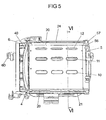
- the lamp housing 2 contains according to the Fig. 1 to 3 . 5 and 6 a jacket flow plate 20 and a plurality of cooling channels 21 to 26 arranged around the jacket flow plate 20, which extend parallel to the optical axis of the headlight and have a profiled but not necessarily ribbed outer surface for enlarging the heat-emitting surface.
- the cooling channels 21 to 26 are arranged at a short distance from the jacket flow plate 20, so that between the jacket flow plate 20 and the cooling channels 21 to 26, a gap 10 is formed.
- the jacket flow sheet 20 is painted with a heat-resistant black lacquer and is preferably made of an aluminum casting or die-cast alloy.
- the sheath lamination sheet 20 may be provided with a low-reflection cohesive ceramic coating applied in a plasma-chemical finishing process.
- the plasma-chemical process takes place in special aqueous-organic electrolytes in which the sheath current plate 20 is connected as an anode, so that the metal is partially melted by the action of the oxygen plasma generated in the electrolyte on the surface of the sheath flow plate 20 and a firmly adhering oxide ceramic metal composite arises on the sheath current sheet 20, which has good scattering properties.
- the jacket flow plate 20 is open to the bottom pan 3 and has the cross-sectional view corresponding to Fig. 3 an omega cross-sectional shape.
- the sheath lamination plate 20 contains a plurality of lenghts arranged side by side in the direction of the optical axis of the headlamp, both in cross-section Fig. 3 as well as the longitudinal section according to Fig. 5 to be taken first openings 11, 12, 13, which on the outside cooling channels 22, 23, 24, 25 at a distance of the gap 10 face.
- FIG. 3 In the cross-sectional view according to Fig. 3 are symbolically registered arrows that characterize the various air currents in the interior and on the outer surface of the jacket flow plate 20. Via not shown air inlet openings in the bottom pan 3 gets cooler outside air into the bottom pan 3 and leads there from the located in the bottom pan 3 electrical and electronic components, such as the ignitor of the headlamp and electrical cables and controls, heat released into the interior 200th of the completed by the sheath plate 20 lamp housing 2 from.
- the heat radiation emitted by the lamp or the burner 8 further heats the inner or first convection flow K1 circulating in the interior 200 of the jacket flow plate 20 of the lamp housing 2 and gives some of the heat to the jacket flow plate 20 and over the upper area of the jacket flow plate 20 first openings 11, 12, 13 in the formed between the sheath louver 20 and the cooling channels 21 to 26 gap 10 from.
- a cooling air flow K3 is guided in the cooling channels 21 to 26, which are arranged in accordance with FIG Fig. 4 via front cooling channel openings 41 to 46 of the cooling channels 21 to 26 and according to Fig. 2 are guided over the rear cooling channel openings 51 to 56.
- the cooling air flow K3 guided through the cooling channels 21 to 26 is used as inlet openings to the rear cooling channel openings 51 to 56 as inlet openings to the rear side cooling channel openings 41 to 46 and downwards from the rear cooling channel openings 51 to 56 as inlet openings directed to the front side cooling channel openings 41 to 46 as outlet openings.
- openings 50, 57, 58, 59 can be arranged on the outer periphery of the back part 5, via which, with the headlight inclined, the outer convection flow K2 guided on the outside of the jacket flow plate 20 is discharged through the rear part 5 to the environment becomes.
- 5 covered air outlet slots 501, 502, 503 can be provided in the region of the central surface of the rear part, is discharged through the in the interior 200 of the lamp housing 2, that is located within the jacket flow plate 20 heated air, especially with tilted headlights.
- laterally arranged on the floor pan 3 cooling boxes according to the cited above WO 2004/029507 A1 provide and provide with straight or bent blades for targeted air flow guidance for a convection flow.
Landscapes
- Engineering & Computer Science (AREA)
- General Engineering & Computer Science (AREA)
- Non-Portable Lighting Devices Or Systems Thereof (AREA)
- Arrangement Of Elements, Cooling, Sealing, Or The Like Of Lighting Devices (AREA)
- Projection Apparatus (AREA)
Claims (11)
- Système de refroidissement pour un projecteur servant à dériver la chaleur émise par une source lumineuse (8) et/ou par des composants électriques et électroniques optiques ou parcourus par le courant dans un boîtier de projecteur (1) avec un boîtier d'éclairage (2) et un carter de fond (3) comportant :- un premier dispositif de refroidissement (11 - 20) à l'intérieur duquel un premier flux de convection (K1) est guidé à travers l'espace intérieur (200) du carter de fond (3) et à travers le boîtier d'éclairage (2) et qui est traversé par un second flux de convection (K2) traversant le boîtier d'éclairage (2) au moins partiellement dans le sens de la périphérie, et- un second dispositif de refroidissement (21 - 26) pour un flux d'air de refroidissement (K3) orienté essentiellement de manière transversale par rapport au second flux de convection (K2) et s'étendant de manière parallèle par rapport à l'axe optique du projecteur.
- Système de refroidissement selon la revendication 1, caractérisé en ce que le premier dispositif de refroidissement (11 - 20) se compose d'un tôle d'écoulement à gaine (20) disposé dans le boîtier d'éclairage (2), dans la section (supérieure) placée dans le sens opposé à la gravitation duquel sont disposées des premières ouvertures (11 - 13), en ce que le second dispositif de refroidissement se compose de canaux de refroidissement (21 - 26), lesquels sont disposés dans le boîtier d'éclairage (2) de manière parallèle par rapport à l'axe optique du projecteur en s'étendant autour du tôle d'écoulement à gaine (20) et sont espacés de manière radiale par rapport au tôle d'écoulement à gaine (20) et guident le flux d'air de refroidissement (K3) dans la direction longitudinale du boîtier du projecteur (1), et en ce que sont prévues des secondes ouvertures (14 - 19) des canaux de refroidissement (21 - 26) pour le passage des premier et second flux de convection (K1, K2) entre les canaux de refroidissement (21 - 26) s'étendant essentiellement de manière parallèle par rapport à l'axe optique du projecteur.
- Système de refroidissement selon la revendication 2, caractérisé en ce que les canaux de refroidissement (21 - 26) sont légèrement espacés de manière radiale par rapport au tôle d'écoulement à gaine (20), et en ce que le second flux de convection (K2) s'étend à travers la fente (10) formée entre le tôle d'écoulement à gaine (20) et les canaux de refroidissement (21 - 26).
- Système de refroidissement selon la revendication 2 ou 3, caractérisé en ce que les secondes ouvertures (14 - 19) s'étendent essentiellement de manière parallèle par rapport à l'axe optique en partant du côté frontal vers le côté arrière du boîtier d'éclairage (2).
- Système de refroidissement selon l'une quelconque des revendications 2 à 4, caractérisé en ce que les premières et secondes ouvertures (11 - 13 ; 14 - 19) sont disposées de manière décalée les unes par rapport aux autres dans le sens de la périphérie du boîtier d'éclairage (2).
- Système de refroidissement selon au moins l'une quelconque des revendications précédentes 2 à 5, caractérisé en ce que les canaux de refroidissement (21 - 26) comportent des ouvertures de canaux de refroidissement (41 - 46 ; 51 - 56) au niveau du côté frontal et au niveau du côté arrière du boîtier d'éclairage (2).
- Système de refroidissement selon au moins l'une quelconque des revendications précédentes 2 à 6, caractérisé en ce que le tôle d'écoulement à gaine (20) est peint avec une peinture noire résistante à la chaleur.
- Système de refroidissement selon au moins l'une quelconque des revendications précédentes, caractérisé en ce que le tôle d'écoulement à gaine (20) se compose d'un alliage de fonte d'aluminium ou d'un alliage à coulée sous pression.
- Système de refroidissement selon au moins l'une quelconque des revendications précédentes, caractérisé en ce que le tôle d'écoulement à gaine (20) présente un revêtement en céramique appliqué au cours d'un procédé d'amélioration plasma-chimique, présentant un faible coefficient de réflexion.
- Système de refroidissement selon au moins l'une quelconque des revendications précédentes, caractérisé en ce que sont disposés une source lumineuse (8) et un réflecteur (9) dans le boîtier d'éclairage (2) essentiellement cylindrique, comportant le tôle d'écoulement à gaine (20) et les canaux de refroidissement (21 - 26), lequel réflecteur réfléchit les rayons lumineux émis par la source lumineuse (8) vers une ouverture de sortie de la lumière du boîtier d'éclairage (2), laquelle ouverture de sortie de la lumière est recouverte d'une vitre (40) translucide, et en ce que des composants électriques et électroniques tels qu'un appareil d'allumage, des conduites de câble et similaire sont disposés dans le carter de fond (3) disposé dans le sens de gravitation en dessous du boîtier d'éclairage (2) et étant essentiellement en forme parallélépipédique ou polygonale.
- Système de refroidissement selon la revendication 10, caractérisé en ce que le carter de fond (3) présente des ouvertures d'entrée d'air pour l'air de refroidissement, et en ce que l'air réchauffé par les éléments de fonction dans le carter de fond (3) est orienté dans l'espace intérieur (200) du tôle d'écoulement à gaine (20) du boîtier d'éclairage (2) disposé au-dessus du carter de fond (3).
Applications Claiming Priority (2)
| Application Number | Priority Date | Filing Date | Title |
|---|---|---|---|
| DE202005013244U DE202005013244U1 (de) | 2005-08-18 | 2005-08-18 | Kühlsystem für einen Scheinwerfer |
| PCT/EP2006/008181 WO2007020108A1 (fr) | 2005-08-18 | 2006-08-18 | Systeme de refroidissement pour projecteur |
Publications (2)
| Publication Number | Publication Date |
|---|---|
| EP1915569A1 EP1915569A1 (fr) | 2008-04-30 |
| EP1915569B1 true EP1915569B1 (fr) | 2010-01-13 |
Family
ID=35483660
Family Applications (1)
| Application Number | Title | Priority Date | Filing Date |
|---|---|---|---|
| EP06776971A Expired - Fee Related EP1915569B1 (fr) | 2005-08-18 | 2006-08-18 | Systeme de refroidissement pour projecteur |
Country Status (5)
| Country | Link |
|---|---|
| US (1) | US7857491B2 (fr) |
| EP (1) | EP1915569B1 (fr) |
| JP (1) | JP4700734B2 (fr) |
| DE (2) | DE202005013244U1 (fr) |
| WO (1) | WO2007020108A1 (fr) |
Families Citing this family (7)
| Publication number | Priority date | Publication date | Assignee | Title |
|---|---|---|---|---|
| DE202006017131U1 (de) | 2006-10-12 | 2007-01-25 | Arnold & Richter Cine Technik Gmbh & Co. Betriebs Kg | Scheinwerfer zur Beleuchtung in Film-, Studio-, Event- oder Theaterumgebungen |
| US8004844B2 (en) * | 2008-03-12 | 2011-08-23 | Kmw, Inc. | Enclosure device of wireless communication apparatus |
| FR2937403B1 (fr) * | 2008-10-17 | 2013-05-03 | Rve Technologie | Projecteur d'eclairage a dispositif d'evacuation d'energie |
| CN102748670A (zh) * | 2012-06-21 | 2012-10-24 | 上海半导体照明工程技术研究中心 | 一种led投射灯 |
| CN103438385A (zh) * | 2013-03-25 | 2013-12-11 | 郑运婷 | Led路灯 |
| CN103939809B (zh) * | 2014-05-08 | 2017-02-15 | 湖州积微电子科技有限公司 | 一种便于安装的投光灯 |
| USD848054S1 (en) * | 2016-06-01 | 2019-05-07 | Fuzhou F&V Photographic Equipment Co., Ltd. | Spotlight |
Citations (1)
| Publication number | Priority date | Publication date | Assignee | Title |
|---|---|---|---|---|
| WO2004029507A1 (fr) * | 2002-09-20 | 2004-04-08 | Arnold & Richter Cine Technik Gmbh & Co. Betriebs Kg | Projecteur |
Family Cites Families (13)
| Publication number | Priority date | Publication date | Assignee | Title |
|---|---|---|---|---|
| US1758290A (en) * | 1928-06-29 | 1930-05-13 | Mccormack William Eugene | Lantern body for cinematograph and other projection apparatus |
| GB1201894A (en) | 1969-05-16 | 1970-08-12 | Berkey Technical U K Ltd | Improvements in or relating to studio lighting |
| US4546420A (en) * | 1984-05-23 | 1985-10-08 | Wheeler Industries, Ltd. | Air cooled light fixture with baffled flow through a filter array |
| US4658338A (en) * | 1985-07-03 | 1987-04-14 | Quartzcolor Ianiro S.P.A. | Lighting projectors with an intensified and accelerated air flow cooling system for photographic and motion picture studios |
| US4925295A (en) * | 1986-03-17 | 1990-05-15 | Casio Computer Co., Ltd. | Projection display apparatus |
| US5367444A (en) * | 1990-09-06 | 1994-11-22 | Vari-Lite Inc. | Thermal management techniques for lighting instruments |
| US5099399A (en) * | 1991-04-08 | 1992-03-24 | Miller Jack V | High efficiency fiber optics illuminator with thermally controlled light guide bushing |
| US5404283A (en) * | 1992-03-31 | 1995-04-04 | Phoenix Products Company, Inc. | Outdoor framing projector |
| US5172975A (en) * | 1992-04-27 | 1992-12-22 | Mole-Richardson Co. | Light assembly with ventilated housing |
| DE69314122T2 (de) * | 1992-09-04 | 1998-04-02 | Vari Lite Inc | Wärmemanagement-Technik für Beleuchtungsvorrichtungen |
| DE19509480A1 (de) | 1995-03-16 | 1996-09-19 | Ansorg Gmbh | Leuchte |
| JP3376540B2 (ja) * | 1997-09-01 | 2003-02-10 | 株式会社日立製作所 | 液晶プロジェクタ |
| TW479152B (en) * | 2001-02-14 | 2002-03-11 | Acer Peripherals Inc | High thermal diffusion efficiency light device |
-
2005
- 2005-08-18 DE DE202005013244U patent/DE202005013244U1/de not_active Expired - Lifetime
-
2006
- 2006-08-18 WO PCT/EP2006/008181 patent/WO2007020108A1/fr active Application Filing
- 2006-08-18 DE DE502006005927T patent/DE502006005927D1/de active Active
- 2006-08-18 US US11/990,565 patent/US7857491B2/en not_active Expired - Fee Related
- 2006-08-18 JP JP2008526454A patent/JP4700734B2/ja not_active Expired - Fee Related
- 2006-08-18 EP EP06776971A patent/EP1915569B1/fr not_active Expired - Fee Related
Patent Citations (1)
| Publication number | Priority date | Publication date | Assignee | Title |
|---|---|---|---|---|
| WO2004029507A1 (fr) * | 2002-09-20 | 2004-04-08 | Arnold & Richter Cine Technik Gmbh & Co. Betriebs Kg | Projecteur |
Also Published As
| Publication number | Publication date |
|---|---|
| DE202005013244U1 (de) | 2005-12-01 |
| US7857491B2 (en) | 2010-12-28 |
| JP2009505362A (ja) | 2009-02-05 |
| WO2007020108A1 (fr) | 2007-02-22 |
| JP4700734B2 (ja) | 2011-06-15 |
| DE502006005927D1 (de) | 2010-03-04 |
| US20090133857A1 (en) | 2009-05-28 |
| EP1915569A1 (fr) | 2008-04-30 |
Similar Documents
| Publication | Publication Date | Title |
|---|---|---|
| EP1915569B1 (fr) | Systeme de refroidissement pour projecteur | |
| DE102005051248B4 (de) | Lichteinheit, insbesondere für ein Kraftfahrzeug | |
| EP0446423A1 (fr) | Dispositif d'éclairage | |
| DE102009002775A1 (de) | Lampe für Hausgerät sowie Hausgerät, insbesondere zum Zubereiten von Lebensmitteln, mit einer Lampe | |
| DE202009004252U1 (de) | Leuchte | |
| EP2149748B1 (fr) | Phare pour véhicules | |
| EP1902252B1 (fr) | Systeme de refroidissement pour un projecteur | |
| EP2012057B1 (fr) | Luminaire | |
| EP2168006A1 (fr) | Dispositif d'éclairage pour photographie au flash | |
| EP3911892B1 (fr) | Luminaire avec dissipateur thermique fermé sur la périphérie | |
| DE19603025C2 (de) | Beleuchtungsvorrichtung zur Einspeisung von Licht in Lichtleitfasern | |
| DE102010054592B4 (de) | Kühlvorrichtung zum Kühlen von Bauteilen | |
| DE10216249A1 (de) | Leuchte mit Diffusor-Korb | |
| EP1546605B1 (fr) | Projecteur | |
| DE202012101368U1 (de) | Leuchte | |
| DE102005054031B4 (de) | Hochleistungsleuchte mit Kühlmantel | |
| DE10300416A1 (de) | Scheinwerfer für Fahrzeuge | |
| DE10101005B4 (de) | Kraftfahrzeugleuchte, insbesondere Scheinwerfer | |
| DE102006061619B4 (de) | Fahrzeugscheinwerfer mit einem Projektionssystem | |
| DE102010031193B4 (de) | Einbau-Deckenleuchte mit Kühlsystem | |
| DE10120667A1 (de) | Leuchte mit einer Lampe mit gekühlter Kaltfußstelle | |
| DE19509480A1 (de) | Leuchte | |
| EP0769154B1 (fr) | Generateur de lumiere pour alimenter des fibres optiques | |
| DE7225076U (de) | Lampenhaus für Halogenprojektionslampen | |
| DE102011055234A1 (de) | Beleuchtungssystem für ein Kraftfahrzeug und Verfahren zur Unterstützung der natürlichen Luftzirkulation in einem Beleuchtungssystem |
Legal Events
| Date | Code | Title | Description |
|---|---|---|---|
| PUAI | Public reference made under article 153(3) epc to a published international application that has entered the european phase |
Free format text: ORIGINAL CODE: 0009012 |
|
| 17P | Request for examination filed |
Effective date: 20080225 |
|
| AK | Designated contracting states |
Kind code of ref document: A1 Designated state(s): DE FR GB IT |
|
| DAX | Request for extension of the european patent (deleted) | ||
| RBV | Designated contracting states (corrected) |
Designated state(s): DE FR GB IT |
|
| RTI1 | Title (correction) |
Free format text: COOLING SYSTEM FOR A PROJECTOR |
|
| GRAP | Despatch of communication of intention to grant a patent |
Free format text: ORIGINAL CODE: EPIDOSNIGR1 |
|
| GRAS | Grant fee paid |
Free format text: ORIGINAL CODE: EPIDOSNIGR3 |
|
| GRAA | (expected) grant |
Free format text: ORIGINAL CODE: 0009210 |
|
| AK | Designated contracting states |
Kind code of ref document: B1 Designated state(s): DE FR GB IT |
|
| REG | Reference to a national code |
Ref country code: GB Ref legal event code: FG4D Free format text: NOT ENGLISH |
|
| REF | Corresponds to: |
Ref document number: 502006005927 Country of ref document: DE Date of ref document: 20100304 Kind code of ref document: P |
|
| PLBE | No opposition filed within time limit |
Free format text: ORIGINAL CODE: 0009261 |
|
| STAA | Information on the status of an ep patent application or granted ep patent |
Free format text: STATUS: NO OPPOSITION FILED WITHIN TIME LIMIT |
|
| 26N | No opposition filed |
Effective date: 20101014 |
|
| REG | Reference to a national code |
Ref country code: FR Ref legal event code: PLFP Year of fee payment: 10 |
|
| PGFP | Annual fee paid to national office [announced via postgrant information from national office to epo] |
Ref country code: DE Payment date: 20150720 Year of fee payment: 10 Ref country code: GB Payment date: 20150824 Year of fee payment: 10 |
|
| PGFP | Annual fee paid to national office [announced via postgrant information from national office to epo] |
Ref country code: FR Payment date: 20150824 Year of fee payment: 10 |
|
| PGFP | Annual fee paid to national office [announced via postgrant information from national office to epo] |
Ref country code: IT Payment date: 20150827 Year of fee payment: 10 |
|
| REG | Reference to a national code |
Ref country code: DE Ref legal event code: R119 Ref document number: 502006005927 Country of ref document: DE |
|
| GBPC | Gb: european patent ceased through non-payment of renewal fee |
Effective date: 20160818 |
|
| REG | Reference to a national code |
Ref country code: FR Ref legal event code: ST Effective date: 20170428 |
|
| PG25 | Lapsed in a contracting state [announced via postgrant information from national office to epo] |
Ref country code: DE Free format text: LAPSE BECAUSE OF NON-PAYMENT OF DUE FEES Effective date: 20170301 Ref country code: GB Free format text: LAPSE BECAUSE OF NON-PAYMENT OF DUE FEES Effective date: 20160818 Ref country code: FR Free format text: LAPSE BECAUSE OF NON-PAYMENT OF DUE FEES Effective date: 20160831 |
|
| PG25 | Lapsed in a contracting state [announced via postgrant information from national office to epo] |
Ref country code: IT Free format text: LAPSE BECAUSE OF NON-PAYMENT OF DUE FEES Effective date: 20160818 |