EP1915569B1 - Cooling system for a projector - Google Patents
Cooling system for a projector Download PDFInfo
- Publication number
- EP1915569B1 EP1915569B1 EP06776971A EP06776971A EP1915569B1 EP 1915569 B1 EP1915569 B1 EP 1915569B1 EP 06776971 A EP06776971 A EP 06776971A EP 06776971 A EP06776971 A EP 06776971A EP 1915569 B1 EP1915569 B1 EP 1915569B1
- Authority
- EP
- European Patent Office
- Prior art keywords
- cooling
- lamp housing
- cooling system
- openings
- flow plate
- Prior art date
- Legal status (The legal status is an assumption and is not a legal conclusion. Google has not performed a legal analysis and makes no representation as to the accuracy of the status listed.)
- Not-in-force
Links
- 238000001816 cooling Methods 0.000 title claims description 84
- 230000003287 optical effect Effects 0.000 claims description 15
- 229910052782 aluminium Inorganic materials 0.000 claims description 4
- XAGFODPZIPBFFR-UHFFFAOYSA-N aluminium Chemical compound [Al] XAGFODPZIPBFFR-UHFFFAOYSA-N 0.000 claims description 4
- 230000005484 gravity Effects 0.000 claims description 4
- 239000000956 alloy Substances 0.000 claims description 3
- 229910045601 alloy Inorganic materials 0.000 claims description 3
- 238000005524 ceramic coating Methods 0.000 claims description 3
- 239000004922 lacquer Substances 0.000 claims description 3
- 238000010028 chemical finishing Methods 0.000 claims description 2
- 239000003570 air Substances 0.000 description 37
- 238000009423 ventilation Methods 0.000 description 8
- 238000000034 method Methods 0.000 description 5
- 230000017525 heat dissipation Effects 0.000 description 4
- 230000005855 radiation Effects 0.000 description 4
- 239000012080 ambient air Substances 0.000 description 2
- 238000005266 casting Methods 0.000 description 2
- 210000000078 claw Anatomy 0.000 description 2
- 230000006378 damage Effects 0.000 description 2
- 230000000694 effects Effects 0.000 description 2
- 238000003475 lamination Methods 0.000 description 2
- 230000001681 protective effect Effects 0.000 description 2
- 230000002411 adverse Effects 0.000 description 1
- QVGXLLKOCUKJST-UHFFFAOYSA-N atomic oxygen Chemical compound [O] QVGXLLKOCUKJST-UHFFFAOYSA-N 0.000 description 1
- 230000015572 biosynthetic process Effects 0.000 description 1
- 239000000919 ceramic Substances 0.000 description 1
- 238000001311 chemical methods and process Methods 0.000 description 1
- 238000004040 coloring Methods 0.000 description 1
- 239000003792 electrolyte Substances 0.000 description 1
- 239000011521 glass Substances 0.000 description 1
- 238000010438 heat treatment Methods 0.000 description 1
- 230000007774 longterm Effects 0.000 description 1
- 239000000463 material Substances 0.000 description 1
- 229910052751 metal Inorganic materials 0.000 description 1
- 239000002184 metal Substances 0.000 description 1
- 239000002905 metal composite material Substances 0.000 description 1
- 229910001507 metal halide Inorganic materials 0.000 description 1
- 150000005309 metal halides Chemical class 0.000 description 1
- 239000005486 organic electrolyte Substances 0.000 description 1
- 238000013021 overheating Methods 0.000 description 1
- 239000011224 oxide ceramic Substances 0.000 description 1
- 229910052574 oxide ceramic Inorganic materials 0.000 description 1
- 229910052760 oxygen Inorganic materials 0.000 description 1
- 239000001301 oxygen Substances 0.000 description 1
- 238000007670 refining Methods 0.000 description 1
- 230000003595 spectral effect Effects 0.000 description 1
- 239000000126 substance Substances 0.000 description 1
Images


Classifications
-
- F—MECHANICAL ENGINEERING; LIGHTING; HEATING; WEAPONS; BLASTING
- F21—LIGHTING
- F21V—FUNCTIONAL FEATURES OR DETAILS OF LIGHTING DEVICES OR SYSTEMS THEREOF; STRUCTURAL COMBINATIONS OF LIGHTING DEVICES WITH OTHER ARTICLES, NOT OTHERWISE PROVIDED FOR
- F21V29/00—Protecting lighting devices from thermal damage; Cooling or heating arrangements specially adapted for lighting devices or systems
- F21V29/50—Cooling arrangements
- F21V29/70—Cooling arrangements characterised by passive heat-dissipating elements, e.g. heat-sinks
- F21V29/83—Cooling arrangements characterised by passive heat-dissipating elements, e.g. heat-sinks the elements having apertures, ducts or channels, e.g. heat radiation holes
-
- F—MECHANICAL ENGINEERING; LIGHTING; HEATING; WEAPONS; BLASTING
- F21—LIGHTING
- F21V—FUNCTIONAL FEATURES OR DETAILS OF LIGHTING DEVICES OR SYSTEMS THEREOF; STRUCTURAL COMBINATIONS OF LIGHTING DEVICES WITH OTHER ARTICLES, NOT OTHERWISE PROVIDED FOR
- F21V29/00—Protecting lighting devices from thermal damage; Cooling or heating arrangements specially adapted for lighting devices or systems
- F21V29/50—Cooling arrangements
- F21V29/60—Cooling arrangements characterised by the use of a forced flow of gas, e.g. air
-
- F—MECHANICAL ENGINEERING; LIGHTING; HEATING; WEAPONS; BLASTING
- F21—LIGHTING
- F21V—FUNCTIONAL FEATURES OR DETAILS OF LIGHTING DEVICES OR SYSTEMS THEREOF; STRUCTURAL COMBINATIONS OF LIGHTING DEVICES WITH OTHER ARTICLES, NOT OTHERWISE PROVIDED FOR
- F21V29/00—Protecting lighting devices from thermal damage; Cooling or heating arrangements specially adapted for lighting devices or systems
- F21V29/50—Cooling arrangements
- F21V29/70—Cooling arrangements characterised by passive heat-dissipating elements, e.g. heat-sinks
- F21V29/74—Cooling arrangements characterised by passive heat-dissipating elements, e.g. heat-sinks with fins or blades
- F21V29/76—Cooling arrangements characterised by passive heat-dissipating elements, e.g. heat-sinks with fins or blades with essentially identical parallel planar fins or blades, e.g. with comb-like cross-section
-
- F—MECHANICAL ENGINEERING; LIGHTING; HEATING; WEAPONS; BLASTING
- F21—LIGHTING
- F21W—INDEXING SCHEME ASSOCIATED WITH SUBCLASSES F21K, F21L, F21S and F21V, RELATING TO USES OR APPLICATIONS OF LIGHTING DEVICES OR SYSTEMS
- F21W2131/00—Use or application of lighting devices or systems not provided for in codes F21W2102/00-F21W2121/00
- F21W2131/40—Lighting for industrial, commercial, recreational or military use
- F21W2131/406—Lighting for industrial, commercial, recreational or military use for theatres, stages or film studios
Definitions
- the invention relates to a cooling system for a headlight.
- a headlamp which consists of a lamp housing or a one-sided or two-capped light source, which consists of a lamp or a burner, for example a discharge lamp in the form of a metal halide lamp, and a reflector, that of the light source emitted light reflected in the direction of a front opening of the headlamp housing, which is closed by a transparent cover, such as a protective glass or lens disk.
- this consists of the WO 2004/029 507 A1 known headlight housing of an upper, cylindrical headlight housing part and a lower, cuboid-shaped headlight housing part, are arranged on the ventilation shafts with separate ventilation channels.
- the ventilation channels are separated by lamellae, which have within the ventilation shaft adjacent to the air inlet openings first fin section and adjacent to the air outlet openings second, opposite the first fin section slit section.
- the slats are bent outside of the cylindrical headlight housing and crimped at their ends, so that on the one hand avoided the leakage of light from the interior of the headlight housing and on the other hand, the air flow is directed perpendicularly away from the headlight housing.
- From the US 1 758 290 A is a headlight housing with arranged on the housing walls ventilation ducts with separate ventilation ducts, which are separated by lamellae, so that there are uniform ventilation ducts, flows through the cooling air into the interior of the spotlight housing.
- the heat radiation emitted by the light source is also of other electrical and electronic components such as an ignitor and the electrical Supply lines heat to the interior of the headlamp housing, which is also dissipated by a convective cooling process.
- the headlamp housing known headlamps are designed voluminous and heavily ribbed on its outer surface to increase the heat-emitting housing surface.
- Object of the present invention is to provide a cooling system for a headlamp of the type mentioned, which dissipates the output of a light source and other components of the headlamp even with horizontally inclined headlight with maximum effect with minimal housing dimensions and located inside the headlight housing Cools components effectively.
- the solution according to the invention makes use of both a convective air flow in the interior of the headlight housing and a convection flow extending around the headlight housing and a cooling air flow directed perpendicularly or transversely at least to the convection flow flowing around the headlight housing. While the inner convective flow receives the heat emitted by the light source and the heat generating components, rises and trailing cooler air from below, the convection flow flowing around the headlight housing causes cooling of the headlight housing.
- the cooling air flow running transversely to these flows carries the heat load in the convection flow partly and in particular even when the headlamp is operated inclined relative to the horizontal.
- Another advantage of the solution according to the invention is that the cooling air flow surrounding the convective air flows is significantly cooler than the convective air flows, so that the cooling system according to the invention also ensures improved contact protection.
- the cooling system for a headlamp for dissipating the output from a light source and / or optical or current-carrying electrical and electronic components in a headlight housing with a lamp housing and a bottom pan heat with a guided inside the bottom trough and the lamp housing of the headlight housing first convection flow through a first Cooling device for a second convection flow flowing around the lamp housing at least partially in the circumferential direction and a second cooling device for a cooling air flow directed essentially perpendicular to the second convection flow and running parallel to the optical axis of the headlight.
- the first cooling device comprises a arranged in the lamp housing sheath current sheet in the interior of the first convection flow is guided and flows around the second Konvetationsströmung
- the second cooling device consists of cooling channels, which are parallel to the optical Axis of the headlamp extending around the sheath current plate and are arranged at a radial distance to the sheath current plate in the lamp housing and the cooling air flow in the longitudinal direction of the headlight housing, wherein the cooling channels are arranged at a small radial distance from the sheath flow sheet and the second convection flow formed by the between the sheath flow sheet and the cooling channels Gap runs.
- the convection flows and the cooling air flow are deliberately guided, which is strengthened by the formation of a gap between the sheath flow sheet and arranged at a small radial distance to the sheath flow cooling ducts guided around the sheath flow convection and emits a portion of the heat load to the cooling channels ,
- first openings are arranged, which serve the heat removal from the inner convection flow to the outer convection flow or the cooling channels and the environment.
- cooling channels between the substantially parallel to the optical axis extending cooling channels second openings for the passage of the convection flow can be provided, which serve to dissipate the heated air to the environment.
- the second openings are formed parallel to the optical axis of the headlamp extending continuously from the front to the back of the headlight housing.
- An advantageous development of the invention is characterized in that a plurality of distributed over the circumference of the headlight housing second openings are provided so that the heat dissipated by the convection flow heat to no strong heating of the headlight housing against the gravitational direction, ie from bottom to top.
- the first and second openings are arranged offset from one another in the circumferential direction of the headlight housing.
- the cooling channels form cooling channel openings at the front and rear of the headlight housing, so that a cooling air flow is generated, which is amplified in one or the other direction with a tilt of the headlight and provides for effective heat dissipation, especially in these critical operating conditions of the headlamp.
- the sheath sheet can be painted with a heat-resistant black lacquer and made of an aluminum casting or die-cast alloy consist.
- the sheath current sheet may be provided with a low reflection coefficient ceramic coating preferably deposited in a plasma chemical refining process.
- the headlight housing consists of a substantially cylindrical lamp housing, in which a light source and a reflector are arranged, which reflects the light beams emitted by the light source to a light exit opening of the lamp housing, which is covered with a translucent disc, and a arranged in the direction of gravity below the lamp housing substantially rectangular or polygonal base pan, are arranged in the electrical and electronic components, such as an ignitor, cable feeds and the like, wherein the lamp housing comprises the sheath current sheet and the cooling channels, the bottom pan has air inlet openings for cooling air and in the Bottom pan heated air is directed into the interior of the sheath flow plate of the above the bottom pan arranged lamp housing.
- This embodiment of the solution according to the invention ensures an optimized convection flow for dissipating the heat emitted by the electrical and electronic components in the floor pan and the radiant heat emitted by the light source in the lamp housing even with a relative to the horizontal tilted headlights and allows a headlight housing with minimal dimensions at the same time improved contact protection.
- Fig. 1 shows a perspective front view of a headlight with a headlight housing 1, which consists of a lamp housing 2 and a bottom tray 3.
- the lamp housing 2 has a front part 4 and a rear part 5, which are usually made of die-cast aluminum.
- the front part 4 includes a front lens 40 and is connected to a lens mount or attachment 6, which is distributed over the circumference evenly distributed four retaining claws 60 for receiving attachment elements such as diffusers, filter discs, protective screens and the like and a unspecified clamping device with the lamp housing 2 is connected.
- a headband 7 is connected to the lamp housing 2 via a Bügelanlenkung.
- the lamp housing 2 surrounds according to the cross-sectional view in FIG Fig. 3 a lamp or a burner 8 and a reflector 9, the light beams emitted by the lamp or the burner 8 in the direction of the front lens 40 according to Fig. 1 reflected.
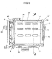
- the lamp housing 2 contains according to the Fig. 1 to 3 . 5 and 6 a jacket flow plate 20 and a plurality of cooling channels 21 to 26 arranged around the jacket flow plate 20, which extend parallel to the optical axis of the headlight and have a profiled but not necessarily ribbed outer surface for enlarging the heat-emitting surface.
- the cooling channels 21 to 26 are arranged at a short distance from the jacket flow plate 20, so that between the jacket flow plate 20 and the cooling channels 21 to 26, a gap 10 is formed.
- the jacket flow sheet 20 is painted with a heat-resistant black lacquer and is preferably made of an aluminum casting or die-cast alloy.
- the sheath lamination sheet 20 may be provided with a low-reflection cohesive ceramic coating applied in a plasma-chemical finishing process.
- the plasma-chemical process takes place in special aqueous-organic electrolytes in which the sheath current plate 20 is connected as an anode, so that the metal is partially melted by the action of the oxygen plasma generated in the electrolyte on the surface of the sheath flow plate 20 and a firmly adhering oxide ceramic metal composite arises on the sheath current sheet 20, which has good scattering properties.
- the jacket flow plate 20 is open to the bottom pan 3 and has the cross-sectional view corresponding to Fig. 3 an omega cross-sectional shape.
- the sheath lamination plate 20 contains a plurality of lenghts arranged side by side in the direction of the optical axis of the headlamp, both in cross-section Fig. 3 as well as the longitudinal section according to Fig. 5 to be taken first openings 11, 12, 13, which on the outside cooling channels 22, 23, 24, 25 at a distance of the gap 10 face.
- FIG. 3 In the cross-sectional view according to Fig. 3 are symbolically registered arrows that characterize the various air currents in the interior and on the outer surface of the jacket flow plate 20. Via not shown air inlet openings in the bottom pan 3 gets cooler outside air into the bottom pan 3 and leads there from the located in the bottom pan 3 electrical and electronic components, such as the ignitor of the headlamp and electrical cables and controls, heat released into the interior 200th of the completed by the sheath plate 20 lamp housing 2 from.
- the heat radiation emitted by the lamp or the burner 8 further heats the inner or first convection flow K1 circulating in the interior 200 of the jacket flow plate 20 of the lamp housing 2 and gives some of the heat to the jacket flow plate 20 and over the upper area of the jacket flow plate 20 first openings 11, 12, 13 in the formed between the sheath louver 20 and the cooling channels 21 to 26 gap 10 from.
- a cooling air flow K3 is guided in the cooling channels 21 to 26, which are arranged in accordance with FIG Fig. 4 via front cooling channel openings 41 to 46 of the cooling channels 21 to 26 and according to Fig. 2 are guided over the rear cooling channel openings 51 to 56.
- the cooling air flow K3 guided through the cooling channels 21 to 26 is used as inlet openings to the rear cooling channel openings 51 to 56 as inlet openings to the rear side cooling channel openings 41 to 46 and downwards from the rear cooling channel openings 51 to 56 as inlet openings directed to the front side cooling channel openings 41 to 46 as outlet openings.
- openings 50, 57, 58, 59 can be arranged on the outer periphery of the back part 5, via which, with the headlight inclined, the outer convection flow K2 guided on the outside of the jacket flow plate 20 is discharged through the rear part 5 to the environment becomes.
- 5 covered air outlet slots 501, 502, 503 can be provided in the region of the central surface of the rear part, is discharged through the in the interior 200 of the lamp housing 2, that is located within the jacket flow plate 20 heated air, especially with tilted headlights.
- laterally arranged on the floor pan 3 cooling boxes according to the cited above WO 2004/029507 A1 provide and provide with straight or bent blades for targeted air flow guidance for a convection flow.
Landscapes
- Engineering & Computer Science (AREA)
- General Engineering & Computer Science (AREA)
- Non-Portable Lighting Devices Or Systems Thereof (AREA)
- Arrangement Of Elements, Cooling, Sealing, Or The Like Of Lighting Devices (AREA)
- Projection Apparatus (AREA)
Description
Die Erfindung betrifft ein Kühlsystem für einen Scheinwerfer.The invention relates to a cooling system for a headlight.
Aus der
Neben der Abstrahlung von sichtbaren Lichtstrahlen erzeugt eine brennende Lichtquelle in ihrem Lichtbogen bzw. in ihrem Filament auch im infraroten Spektralbereich liegende, nicht sichtbare Wärmestrahlung, die durch die folgenden drei Prozesse an die Umgebung der Lichtquelle abgegeben wird:
- a) die Wärmestrahlung wird von den die Lichtquelle umgebenden Bauteilen wie Reflektor, Lichtquellensockel und Zuleitungen zur Lichtquelle sowie vom Scheinwerfergehäuse teilweise absorbiert, die dadurch in ihren Materialeigenschaften negativ beeinflusst werden und selbst als sekundäre Wärmequelle wirken,
- b) über die elektrischen Kontakte und über den Keramikkörper des Lichtquellensockels findet eine Wärmeleitung statt und
- c) die Umgebungsluft der Lichtquelle wird aufgeheizt, steigt nach oben und zieht in einem konvektiven Kühlungsprozess kühlere Luft von unten nach.
- a) the thermal radiation is partially absorbed by the components surrounding the light source such as reflector, light source socket and supply lines to the light source as well as the headlamp housing, which are thereby adversely affected in their material properties and even act as a secondary heat source,
- b) via the electrical contacts and the ceramic body of the light source socket heat conduction takes place and
- c) the ambient air of the light source is heated, rises and draws cooler air from below in a convective cooling process.
Um den letztgenannten Prozess zu unterstützen und einen Scheinwerfer großer Lichtleistung mit kompakter Bauform zu schaffen, besteht das aus der
Aus der
Aus der
Neben der von der Lichtquelle abgegebenen Wärmestrahlung wird auch von weiteren elektrischen und elektronischen Bauteilen wie einem Zündgerät und den elektrischen Zuleitungen Wärme an das Innere des Scheinwerfergehäuses abgegeben, die ebenfalls durch einen konvektiven Kühlungsprozess abzuführen ist.In addition to the heat radiation emitted by the light source is also of other electrical and electronic components such as an ignitor and the electrical Supply lines heat to the interior of the headlamp housing, which is also dissipated by a convective cooling process.
Ein weiteres Problem bei der Wärmeabfuhr aus einem Scheinwerfergehäuse besteht darin, dass bei einer Neigung des Scheinwerfers gegenüber der Waagerechten die konvektive Luftströmung in höher liegende Teile des Scheinwerfergehäuses geführt wird, so dass es leicht zu lokalen Überhitzungen und in Folge davon zur Beschädigung oder Zerstörung von Bauteilen kommen kann.Another problem with heat dissipation from a headlamp housing is that when the headlamp is tilted in relation to the horizontal, the convective air flow is directed to higher parts of the headlamp housing, making it easy for local overheating and consequent damage or destruction of components can come.
Um der konvektiven Luftströmung hinreichend Raum zu geben und die erhitzte Luft besser an die Umgebung des Scheinwerfers abzuführen, werden die Scheinwerfergehäuse bekannter Scheinwerfer großvolumig ausgelegt und an Ihrer Außenfläche stark gerippt, um die Wärme abgebende Gehäusefläche zu vergrößern.In order to give the convective air flow sufficient space and dissipate the heated air better to the environment of the headlamp, the headlamp housing known headlamps are designed voluminous and heavily ribbed on its outer surface to increase the heat-emitting housing surface.
Aufgabe der vorliegenden Erfindung ist es, ein Kühlsystem für einen Scheinwerfer der eingangs genannten Art anzugeben, das die von einer Lichtquelle und anderen Bauteilen des Scheinwerfers abgegebene Wärme auch bei gegenüber der Waagerechten geneigtem Scheinwerfer mit größtmöglicher Wirkung bei minimalen Gehäuseabmessungen abführt und im Inneren des Scheinwerfergehäuses befindliche Bauteile wirksam kühlt.Object of the present invention is to provide a cooling system for a headlamp of the type mentioned, which dissipates the output of a light source and other components of the headlamp even with horizontally inclined headlight with maximum effect with minimal housing dimensions and located inside the headlight housing Cools components effectively.
Diese Aufgabe wird erfindungsgemäß durch die Merkmale des Anspruchs 1 gelöst.This object is achieved by the features of
Die erfindungsgemäße Lösung macht sowohl von einer konvektiven Luftströmung im Inneren des Scheinwerfergehäuses als auch einer um das Scheinwerfergehäuse verlaufenden Konvektionsströmung sowie einer senkrecht oder quer zumindest zu der das Scheinwerfergehäuse umströmenden Konvektionsströmung gerichteten Kühlluftströmung Gebrauch. Während die innere Konvektionsströmung die von der Lichtquelle und den Wärmeerzeugenden Bauteilen abgegebene Wärme aufnimmt, aufsteigt und kühlere Luft von unten nachzieht, bewirkt die das Scheinwerfergehäuse umströmende Konvektionsströmung eine Kühlung des Scheinwerfergehäuses. Die quer zu diesen Strömungen verlaufende Kühlluftströmung führt die Wärmelast bei der Konvektionsströmung teilweise und insbesondere auch dann ab, wenn der Scheinwerfer gegenüber der Waagerechten geneigt betrieben wird.The solution according to the invention makes use of both a convective air flow in the interior of the headlight housing and a convection flow extending around the headlight housing and a cooling air flow directed perpendicularly or transversely at least to the convection flow flowing around the headlight housing. While the inner convective flow receives the heat emitted by the light source and the heat generating components, rises and trailing cooler air from below, the convection flow flowing around the headlight housing causes cooling of the headlight housing. The cooling air flow running transversely to these flows carries the heat load in the convection flow partly and in particular even when the headlamp is operated inclined relative to the horizontal.
Ein weiterer Vorteil der erfindungsgemäßen Lösung besteht darin, dass die die konvektiven Luftströmungen umgebende Kühlluftströmung deutlich kühler ist als die konvektiven Luftströmungen, so dass das erfindungsgemäße Kühlsystem auch einen verbesserten Berührungsschutz gewährleistet.Another advantage of the solution according to the invention is that the cooling air flow surrounding the convective air flows is significantly cooler than the convective air flows, so that the cooling system according to the invention also ensures improved contact protection.
Dementsprechend ist das Kühlsystem für einen Schweinwerfer zur Ableitung der von einer Lichtquelle und/oder optischen oder stromdurchflossenen elektrischen und elektronischen Bauteilen in einem Scheinwerfergehäuse mit einem Lampengehäuse und einer Bodenwanne abgegebenen Wärme mit einer innerhalb der Bodenwanne und des Lampengehäuse des Scheinwerfergehäuses geführten ersten Konvektionsströmung durch eine erste Kühleinrichtung für eine das Lampengehäuse zumindest teilweise in Umfangsrichtung umströmende zweite Konvektionsströmung und eine zweite Kühleinrichtung für eine im Wesentlichen senkrecht zur zweiten Konvektionsströmung gerichtete und parallel zur optischen Achse des Scheinwerfers verlaufende Kühlluftströmung gekennzeichnet.Accordingly, the cooling system for a headlamp for dissipating the output from a light source and / or optical or current-carrying electrical and electronic components in a headlight housing with a lamp housing and a bottom pan heat with a guided inside the bottom trough and the lamp housing of the headlight housing first convection flow through a first Cooling device for a second convection flow flowing around the lamp housing at least partially in the circumferential direction and a second cooling device for a cooling air flow directed essentially perpendicular to the second convection flow and running parallel to the optical axis of the headlight.
Eine vorteilhafte Ausgestaltung der erfindungsgemäßen Lösung ist dadurch gekennzeichnet, dass die erste Kühleinrichtung ein im Lampengehäuse angeordnetes Mantelstromblech enthält, in dessen Innenraum die erste Konvektionsströmung geführt ist und das von der zweiten Konvektionsströmung umströmt ist, während die zweite Kühleinrichtung aus Kühlkanälen besteht, die parallel zur optischen Achse des Scheinwerfers verlaufend um das Mantelstromblech und mit radialem Abstand zum Mantelstromblech im Lampengehäuse angeordnet sind und die Kühlluftströmung in Längsrichtung des Scheinwerfergehäuses führen, wobei die Kühlkanäle in geringem radialen Abstand zum Mantelstromblech angeordnet sind und die zweite Konvektionsströmung durch den zwischen dem Mantelstromblech und den Kühlkanälen gebildeten Spalt verläuft.An advantageous embodiment of the solution according to the invention is characterized in that the first cooling device comprises a arranged in the lamp housing sheath current sheet in the interior of the first convection flow is guided and flows around the second Konvektionsströmung, while the second cooling device consists of cooling channels, which are parallel to the optical Axis of the headlamp extending around the sheath current plate and are arranged at a radial distance to the sheath current plate in the lamp housing and the cooling air flow in the longitudinal direction of the headlight housing, wherein the cooling channels are arranged at a small radial distance from the sheath flow sheet and the second convection flow formed by the between the sheath flow sheet and the cooling channels Gap runs.
Durch die Anordnung eines Mantelstromblechs werden die Konvektionsströmungen und die Kühlluftströmung gezielt geführt, wobei durch die Ausbildung eines Spaltes zwischen dem Mantelstromblech und den in geringem radialen Abstand zum Mantelstromblech angeordneten Kühlkanälen die um das Mantelstromblech geführte Konvektionsströmung verstärkt wird und einen Teil der Wärmelast an die Kühlkanäle abgibt.By arranging a jacket flow sheet, the convection flows and the cooling air flow are deliberately guided, which is strengthened by the formation of a gap between the sheath flow sheet and arranged at a small radial distance to the sheath flow cooling ducts guided around the sheath flow convection and emits a portion of the heat load to the cooling channels ,
Vorzugsweise sind in dem der Gravitationsrichtung entgegen gesetzten oberen Abschnittes des Mantelstromblechs erste Öffnungen angeordnet, die der Wärmeabfuhr von der inneren Konvektionsströmung an die äußere Konvektionsströmung bzw. die Kühlkanäle und die Umgebung dienen.Preferably, in the direction of gravity opposite upper portion of the Mantelstromblechs first openings are arranged, which serve the heat removal from the inner convection flow to the outer convection flow or the cooling channels and the environment.
Weiterhin können zwischen den im Wesentlichen parallel zur optischen Achse verlaufenden Kühlkanälen zweite Öffnungen zum Durchtritt der Konvektionsströmung vorgesehen werden, die der Abfuhr der erwärmten Luft an die Umgebung dienen.Furthermore, between the substantially parallel to the optical axis extending cooling channels second openings for the passage of the convection flow can be provided, which serve to dissipate the heated air to the environment.
Um die Ableitung der erwärmten Luft an die Umgebung über die gesamte Länge des Scheinwerfers sicher zu stellen, sind nach einem weiteren Merkmal der Erfindung die zweiten Öffnungen parallel zur optischen Achse des Scheinwerfers verlaufend durchgehend von der Frontseite zur Rückseite des Scheinwerfergehäuses ausgebildet.In order to ensure the discharge of the heated air to the environment over the entire length of the headlamp, according to a further feature of the invention, the second openings are formed parallel to the optical axis of the headlamp extending continuously from the front to the back of the headlight housing.
Eine vorteilhafte Weiterbildung der Erfindung ist dadurch gekennzeichnet, dass mehrere über den Umfang des Scheinwerfergehäuses verteilte zweite Öffnungen vorgesehen sind, so dass die mittels der Konvektionsströmung abgeführte Wärme zu keiner starken Erhitzung des Scheinwerfergehäuses entgegen der Gravitationsrichtung, d.h. von unten nach oben führt.An advantageous development of the invention is characterized in that a plurality of distributed over the circumference of the headlight housing second openings are provided so that the heat dissipated by the convection flow heat to no strong heating of the headlight housing against the gravitational direction, ie from bottom to top.
Um ein Austreten von Streulicht aus dem Scheinwerfergehäuse zu verhindern, sind die ersten und zweiten Öffnungen in Umfangsrichtung des Scheinwerfergehäuses versetzt zueinander angeordnet.In order to prevent leakage of stray light from the headlight housing, the first and second openings are arranged offset from one another in the circumferential direction of the headlight housing.
Vorzugsweise bilden die Kühlkanäle Kühlkanalöffnungen an der Front- und Rückseite des Scheinwerfergehäuses aus, so dass eine Kühlluftströmung erzeugt wird, die bei einer Neigung des Scheinwerfers in der einen oder anderen Richtung verstärkt wird und besonders in diesen kritischen Betriebszuständen des Scheinwerfers für eine wirksame Wärmabfuhr sorgt.Preferably, the cooling channels form cooling channel openings at the front and rear of the headlight housing, so that a cooling air flow is generated, which is amplified in one or the other direction with a tilt of the headlight and provides for effective heat dissipation, especially in these critical operating conditions of the headlamp.
Zur Verstärkung der Wärmeabfuhr kann das Mantelstromblech mit einem hitzebeständigen schwarzen Lack lackiert werden und aus einer Aluminium-Guss- oder Druckgusslegierung bestehen. Alternativ kann das Mantelstromblech mit einer vorzugsweise in einem plasmachemischen Veredelungsverfahren aufgebrachten keramischen Beschichtung mit niedrigem Reflexionskoeffizienten versehen werden.To increase the heat dissipation, the sheath sheet can be painted with a heat-resistant black lacquer and made of an aluminum casting or die-cast alloy consist. Alternatively, the sheath current sheet may be provided with a low reflection coefficient ceramic coating preferably deposited in a plasma chemical refining process.
Durch die Erzeugung einer fest haftenden Oxidkeramik-Metall-Verbindung auf dem Mantelstromblech wird eine hohe Hitzebeständigkeit insbesondere der einen niedrigen Reflexionskoeffizienten aufweisenden Färbung des Mantelstrombleches erzielt, die auch unter der Hitzeeinwirkung auf Dauer nicht abblättert.By producing a firmly adhering oxide ceramic-metal compound on the sheath sheet a high heat resistance, in particular the low reflection coefficient having coloring of the sheath current sheet is achieved, which does not peel off even under the effect of heat in the long term.
In einer Ausgestaltung der erfindungsgemäßen Lösung besteht das Scheinwerfergehäuse aus einem im Wesentlichen zylinderförmigen Lampengehäuse, in dem eine Lichtquelle und ein Reflektor angeordnet sind, der die von der Lichtquelle abgegebenen Lichtstrahlen zu einer Lichtaustrittsöffnung des Lampengehäuses reflektiert, die mit einer lichtdurchlässigen Scheibe abgedeckt ist, und einer in Gravitationsrichtung unterhalb des Lampengehäuses angeordneten im Wesentlichen quaderförmigen oder polygonalen Bodenwanne, in der elektrische und elektronische Bauteile, wie ein Zündgerät, Kabelzuführungen und dergleichen angeordnet sind, wobei das Lampengehäuse das Mantelstromblech und die Kühlkanäle umfasst, die Bodenwanne Lufteintrittsöffnungen für Kühlluft aufweist und die in der Bodenwanne erwärmte Luft in den Innenraum des Mantelstromblechs des oberhalb der Bodenwanne angeordneten Lampengehäuses gerichtet ist.In one embodiment of the solution according to the invention, the headlight housing consists of a substantially cylindrical lamp housing, in which a light source and a reflector are arranged, which reflects the light beams emitted by the light source to a light exit opening of the lamp housing, which is covered with a translucent disc, and a arranged in the direction of gravity below the lamp housing substantially rectangular or polygonal base pan, are arranged in the electrical and electronic components, such as an ignitor, cable feeds and the like, wherein the lamp housing comprises the sheath current sheet and the cooling channels, the bottom pan has air inlet openings for cooling air and in the Bottom pan heated air is directed into the interior of the sheath flow plate of the above the bottom pan arranged lamp housing.
Diese Ausgestaltung der erfindungsgemäßen Lösung gewährleistet eine optimierte Konvektionsströmung zur Ableitung der von den elektrischen und elektronischen Bauteilen in der Bodenwanne abgegebenen Wärme sowie der von der Lichtquelle im Lampengehäuse abgegebenen Strahlungswärme auch bei einem gegenüber der Waagerechten geneigt betriebenen Scheinwerfer und ermöglicht ein Scheinwerfergehäuse mit minimalen Abmessungen bei gleichzeitig verbessertem Berührungsschutz.This embodiment of the solution according to the invention ensures an optimized convection flow for dissipating the heat emitted by the electrical and electronic components in the floor pan and the radiant heat emitted by the light source in the lamp housing even with a relative to the horizontal tilted headlights and allows a headlight housing with minimal dimensions at the same time improved contact protection.
Anhand eines in der Zeichnung dargestellten Ausführungsbeispiels soll der der Erfindung zugrunde liegende Gedanke näher erläutert werden. Es zeigen:
- Fig. 1
- eine perspektivische Frontseitenansicht eines Scheinwerfers für Bühnen-, Studio-, Film-, Fernseh- und Eventbeleuchtung mit einem erfindungsgemäßen Kreuzstrom-Kühlsystem;
- Fig. 2
- eine perspektivische Rückseitenansicht des Scheinwerfers gemäß
Fig. 1 ; - Fig. 3
- einen Querschnitt durch den Scheinwerfer gemäß den
Fig. 1 und2 ; - Fig. 4
- eine Vorderansicht des Scheinwerfergehäuses gemäß den
Fig. 1 bis 3 ; - Fig. 5
- einen Längsschnitt durch den das Scheinwerfergehäuse entlang der Linie V-V gemäß
Fig. 4 und - Fig. 6
- einen Querschnitt durch das Scheinwerfergehäuse entlang der Linie VI-VI gemäß
Fig. 5 .
- Fig. 1
- a front perspective view of a spotlight for stage, studio, film, television and event lighting with a cross-flow cooling system according to the invention;
- Fig. 2
- a rear perspective view of the headlamp according to
Fig. 1 ; - Fig. 3
- a cross section through the headlamp according to
Fig. 1 and2 ; - Fig. 4
- a front view of the headlight housing according to the
Fig. 1 to 3 ; - Fig. 5
- a longitudinal section through the headlight housing along the line VV according to
Fig. 4 and - Fig. 6
- a cross section through the headlight housing along the line VI-VI according to
Fig. 5 ,
Das Lampengehäuse 2 umgibt entsprechend der Querschnittsdarstellung in
Das Lampengehäuse 2 enthält gemäß den
Zur Verstärkung der Wärmeabfuhr ist das Mantelstromblech 20 mit einem hitzebeständigen schwarzen Lack lackiert und besteht vorzugsweise aus einer Aluminium-Guss- oder Druckgusslegierung. Alternativ kann das Mantelstromblech 20 zur Erhöhung der Hitzebeständigkeit mit einer in einem plasmachemischen Veredelungsverfahren aufgebrachten, fest haftenden keramischen Beschichtung mit niedrigem Reflexionskoeffizienten versehen werden. Der plasmachemische Prozeß läuft in speziellen wässrig-organischen Elektrolyten ab, in denen das Mantelstromblech 20 als Anode geschaltet ist, so dass durch Einwirkung des im Elektrolyten erzeugten Sauerstoff-Plasmas auf die Oberfläche des Mantelstromblechs 20 das Metall partiell geschmolzen und ein fest haftender Oxidkeramik-Metallverbund auf dem Mantelstromblech 20 entsteht, der gute Streueigenschaften aufweist.To increase the heat dissipation, the
Das Mantelstromblech 20 ist zur Bodenwanne 3 offen und weist entsprechen der Querschnittsdarstellung der
Zwischen den Kühlkanälen 21 bis 26 sowie zwischen den in Umfangsrichtung äußeren Kühlkanälen 21 und 26 und der Bodenwanne 3 sind zweite Öffnungen 14 bis 19 ausgebildet, durch die kühlere Umgebungsluft ein bzw. erhitzte Luft ausströmt.Between the
In die Querschnittsdarstellung gemäß
Über die Öffnungen 14, 19, die zwischen den in Umfangsrichtung äußeren Kühlkanälen 21, 26 und der Bodenwanne 3 ausgebildet sind, wird Luft für die äußere oder zweite Konvektionsströmung K2 angesaugt, die um das Mantelstromblech 20 geführt wird und die Wärmelast teilweise an die Kühlkanäle 21 bis 26 bzw. durch die zweiten Öffnungen 15, 16, 17, 18 an die Umgebung abgibt.Via the
Senkrecht zu den innerhalb des Mantelstromblechs 20 sowie um das Mantelstromblech 20 herum geführten inneren und äußeren bzw. ersten und zweiten Konvektionsströmungen K1 und K2 wird eine Kühlluftströmung K3 in den Kühlkanälen 21 bis 26 geführt, die gemäß
Zusätzlich können im Rückteil 5 des Scheinwerfergehäuses 1 Öffnungen 50, 57, 58, 59 an der äußeren Peripherie des Rückteils 5 angeordnet werden, über die bei geneigtem Scheinwerfer die an der Außenseite des Mantelstromblechs 20 geführte äußere Konvektionsströmung K2 durch das Rückteil 5 an die Umgebung abgegeben wird.In addition, in the
Weiterhin können im Bereich der mittleren Fläche des Rückteils 5 abgedeckte Luftaustrittsschlitze 501, 502, 503 vorgesehen werden, über die im Innenraum 200 des Lampengehäuses 2, das heißt innerhalb des Mantelstromblechs 20 befindliche erhitzte Luft insbesondere bei geneigtem Scheinwerfer abgegeben wird.Furthermore, 5 covered
Es liegt auch im Rahmen der vorliegenden Erfindung, seitlich an der Bodenwanne 3 angeordnete Kühlkästen entsprechend der eingangs zitierten
- 11
- Scheinwerfergehäuseheadlamp housing
- 22
- Lampengehäuselamp housing
- 33
- Bodenwannefloor pan
- 44
- Frontteilfront part
- 55
- Rückteilrear part
- 66
- Vorsatzteilfront attachment
- 77
- Haltebügelheadband
- 88th
- Lampe oder BrennerLamp or burner
- 99
- Reflektorreflector
- 1010
- Spaltgap
- 11 - 1311 - 13
- erste Öffnungenfirst openings
- 14 - 1914 - 19
- zweite Öffnungensecond openings
- 2020
- MantelstromblechJacket flow guide plate
- 21 - 2621 - 26
- Kühlkanälecooling channels
- 4040
- Frontlinsefront lens
- 41 - 4641 - 46
- Frontseitige ÖffnungenFront openings
- 51 - 5951 - 59
- rückseitige Öffnungenback openings
- 6060
- Halteklauenretaining claws
- 200200
- Innenrauminner space
- 501 - 503501 - 503
- LuftaustrittsschlitzeAir outlet slots
- K1K1
- Erste KonvektionsströmungFirst convection flow
- K2K2
- Zweite KonvektionsströmungSecond convection flow
- K3K3
- KühlluftströmungCooling air flow
Claims (11)
- A cooling system for a projector for dissipating the heat output by a light source (8) and/or optical components or electric and electronic components through which current flows in a projector housing (1) with a lamp housing (2) and a base tray (3), with- a first cooling device (11-20) in which a first convection flow (K1) is guided through the interior space (200) of the base tray (3) and the lamp housing (2) and around which a second convection flow (K2) circulates which circulates around the lamp housing (2) at least partially in the circumferential direction, and- a second cooling device (21-26) for a cooling air flow (K3) which is directed substantially perpendicularly to the second convection flow (K2) and runs parallel to the optical axis of the projector.
- The cooling system as claimed in claim 1,
characterized in that the first cooling device (11-20) comprised of a jacket flow plate (20) which is arranged in the lamp housing (2), in whose (upper) section first openings (11-13) are arranged, which (upper) section is counter to the direction of gravity, and in that the second cooling device comprises cooling ducts (21-26), which are arranged in the lamp housing (2) around the jacket flow plate (20) and radially spaced apart from the jacket flow plate (20) wherein they extend parallel to the optical axis of the projector and which guide the cooling air flow (K3) in the longitudinal direction of the projector housing (1), and in that second openings (14-19) of the cooling ducts (21-26) for the passage of the first and second convection flows (K1, K2) are provided between the cooling ducts (21-26) which cooling ducts extend substantially parallel to the optical axis of the projector. - The cooling system as claimed in claim 2,
characterized in that the cooling ducts (21-26) are arranged at a small radial spacing from the jacket flow plate (20) and in that the second convection flow (K2) flows through the gap (10) formed between the jacket flow plate (20) and the cooling ducts (21-26). - The cooling system as claimed in claim 2 or 3, characterized in that the second openings (14-19) extend substantially parallel to the optical axis such that they lead through from the front face to the rear face of the lamp housing (2).
- The cooling system as claimed in one of claims 2 to 4, characterized in that the first and second openings (11-13; 14-19) are arranged offset with respect to one another in the circumferential direction of the lamp housing (2).
- The cooling system as claimed in at least one of the preceding claims 2 to 5, characterized in that the cooling ducts (21-26) form cooling duct openings (41-46; 51-56) at the front and rear faces of the lamp housing (2).
- The cooling system as claimed in at least one of the preceding claims 2 to 6, characterized in that the jacket flow plate (20) is painted with a heat-resistant black lacquer.
- The cooling system as claimed in at least one of the preceding claims, characterized in that the jacket flow plate (20) comprises an aluminum cast or pressure diecast alloy.
- The cooling system as claimed in at least one of the preceding claims, characterized in that the jacket flow plate (20) has a ceramic coating with low reflection coefficient, which is applied in a plasma-chemical finishing process.
- The cooling system as claimed in at least one of the preceding claims, characterized in that in the substantially cylindrical lamp housing (2) which comprises the jacket flow plate (20) and the cooling ducts (21-26), a light source (8) and a reflector (9) are arranged, which reflector reflects the light beams emitted by the light source (8) to a light exit opening of the lamp housing (2), the light exit opening being covered by a transparent plate (40), and in that in the substantially cuboid or polygonal base tray (3) which is arranged in the direction of gravity beneath the lamp housing (2), electric and electronic components, such as an ignitor, cable leads and the like are arranged.
- The cooling system as claimed in claim 10,
characterized in that the base tray (3) has air entrance openings for cooling air and the air heated by the functional elements in the base tray (3) is directed into the interior space (200) of the jacket flow plate (20) of the lamp housing (2) arranged above the base tray (3).
Applications Claiming Priority (2)
| Application Number | Priority Date | Filing Date | Title |
|---|---|---|---|
| DE202005013244U DE202005013244U1 (en) | 2005-08-18 | 2005-08-18 | Cooling system for floodlight, has sheet metal cladding with circumferentially spaced openings provided about lamp housing and enclosed within circumferential array of cooling ducts defining another set of openings |
| PCT/EP2006/008181 WO2007020108A1 (en) | 2005-08-18 | 2006-08-18 | Cooling system for a headlight |
Publications (2)
| Publication Number | Publication Date |
|---|---|
| EP1915569A1 EP1915569A1 (en) | 2008-04-30 |
| EP1915569B1 true EP1915569B1 (en) | 2010-01-13 |
Family
ID=35483660
Family Applications (1)
| Application Number | Title | Priority Date | Filing Date |
|---|---|---|---|
| EP06776971A Not-in-force EP1915569B1 (en) | 2005-08-18 | 2006-08-18 | Cooling system for a projector |
Country Status (5)
| Country | Link |
|---|---|
| US (1) | US7857491B2 (en) |
| EP (1) | EP1915569B1 (en) |
| JP (1) | JP4700734B2 (en) |
| DE (2) | DE202005013244U1 (en) |
| WO (1) | WO2007020108A1 (en) |
Families Citing this family (7)
| Publication number | Priority date | Publication date | Assignee | Title |
|---|---|---|---|---|
| DE202006017131U1 (en) | 2006-10-12 | 2007-01-25 | Arnold & Richter Cine Technik Gmbh & Co. Betriebs Kg | Floodlight for illuminating in films, studios, events and theaters has electrical connection that is rotationally arranged on the spotlight housing |
| WO2009113818A2 (en) * | 2008-03-12 | 2009-09-17 | Kmw Inc. | Enclosure device of wireless communication apparatus |
| FR2937403B1 (en) * | 2008-10-17 | 2013-05-03 | Rve Technologie | LIGHTING PROJECTOR WITH ENERGY DRAINAGE DEVICE |
| CN102748670A (en) * | 2012-06-21 | 2012-10-24 | 上海半导体照明工程技术研究中心 | LED (Light-Emitting Diode) projection lamp |
| CN103438385A (en) * | 2013-03-25 | 2013-12-11 | 郑运婷 | LED (light-emitting diode) streetlamp |
| CN103939809B (en) * | 2014-05-08 | 2017-02-15 | 湖州积微电子科技有限公司 | Projection lamp convenient to install |
| USD848054S1 (en) * | 2016-06-01 | 2019-05-07 | Fuzhou F&V Photographic Equipment Co., Ltd. | Spotlight |
Citations (1)
| Publication number | Priority date | Publication date | Assignee | Title |
|---|---|---|---|---|
| WO2004029507A1 (en) * | 2002-09-20 | 2004-04-08 | Arnold & Richter Cine Technik Gmbh & Co. Betriebs Kg | Projector |
Family Cites Families (13)
| Publication number | Priority date | Publication date | Assignee | Title |
|---|---|---|---|---|
| US1758290A (en) * | 1928-06-29 | 1930-05-13 | Mccormack William Eugene | Lantern body for cinematograph and other projection apparatus |
| GB1201894A (en) | 1969-05-16 | 1970-08-12 | Berkey Technical U K Ltd | Improvements in or relating to studio lighting |
| US4546420A (en) * | 1984-05-23 | 1985-10-08 | Wheeler Industries, Ltd. | Air cooled light fixture with baffled flow through a filter array |
| US4658338A (en) * | 1985-07-03 | 1987-04-14 | Quartzcolor Ianiro S.P.A. | Lighting projectors with an intensified and accelerated air flow cooling system for photographic and motion picture studios |
| US4925295A (en) * | 1986-03-17 | 1990-05-15 | Casio Computer Co., Ltd. | Projection display apparatus |
| US5367444A (en) * | 1990-09-06 | 1994-11-22 | Vari-Lite Inc. | Thermal management techniques for lighting instruments |
| US5099399A (en) * | 1991-04-08 | 1992-03-24 | Miller Jack V | High efficiency fiber optics illuminator with thermally controlled light guide bushing |
| US5404283A (en) * | 1992-03-31 | 1995-04-04 | Phoenix Products Company, Inc. | Outdoor framing projector |
| US5172975A (en) * | 1992-04-27 | 1992-12-22 | Mole-Richardson Co. | Light assembly with ventilated housing |
| DE69314122T2 (en) * | 1992-09-04 | 1998-04-02 | Vari Lite Inc | Thermal management technology for lighting devices |
| DE19509480A1 (en) | 1995-03-16 | 1996-09-19 | Ansorg Gmbh | Lamp for office and room wall and ceiling lights |
| JP3376540B2 (en) * | 1997-09-01 | 2003-02-10 | 株式会社日立製作所 | LCD projector |
| TW479152B (en) * | 2001-02-14 | 2002-03-11 | Acer Peripherals Inc | High thermal diffusion efficiency light device |
-
2005
- 2005-08-18 DE DE202005013244U patent/DE202005013244U1/en not_active Expired - Lifetime
-
2006
- 2006-08-18 US US11/990,565 patent/US7857491B2/en not_active Expired - Fee Related
- 2006-08-18 EP EP06776971A patent/EP1915569B1/en not_active Not-in-force
- 2006-08-18 JP JP2008526454A patent/JP4700734B2/en not_active Expired - Fee Related
- 2006-08-18 WO PCT/EP2006/008181 patent/WO2007020108A1/en active Application Filing
- 2006-08-18 DE DE502006005927T patent/DE502006005927D1/en active Active
Patent Citations (1)
| Publication number | Priority date | Publication date | Assignee | Title |
|---|---|---|---|---|
| WO2004029507A1 (en) * | 2002-09-20 | 2004-04-08 | Arnold & Richter Cine Technik Gmbh & Co. Betriebs Kg | Projector |
Also Published As
| Publication number | Publication date |
|---|---|
| JP4700734B2 (en) | 2011-06-15 |
| JP2009505362A (en) | 2009-02-05 |
| US20090133857A1 (en) | 2009-05-28 |
| US7857491B2 (en) | 2010-12-28 |
| WO2007020108A1 (en) | 2007-02-22 |
| DE202005013244U1 (en) | 2005-12-01 |
| EP1915569A1 (en) | 2008-04-30 |
| DE502006005927D1 (en) | 2010-03-04 |
Similar Documents
| Publication | Publication Date | Title |
|---|---|---|
| EP1915569B1 (en) | Cooling system for a projector | |
| DE3789170T2 (en) | Ventilation system for a stage lamp. | |
| DE102005051248B4 (en) | Light unit, in particular for a motor vehicle | |
| EP0446423A1 (en) | Lighting fixture | |
| DE102009002775A1 (en) | Lamp for household appliance and household appliance, in particular for preparing food, with a lamp | |
| DE202009004252U1 (en) | lamp | |
| EP2149748B1 (en) | Headlamp for vehicles | |
| EP1902252B1 (en) | Cooling system for a projector | |
| EP2012057B1 (en) | Lamp | |
| WO2009010571A1 (en) | Illumination device for flash photography | |
| EP3911892B1 (en) | Lamp with a peripherally closed heatsink | |
| DE19603025C2 (en) | Lighting device for feeding light into optical fibers | |
| DE102010054592B4 (en) | Cooling device for cooling components | |
| DE10216249A1 (en) | Light has diffuser cage with at least one light inlet opening on at least one side of lamp chamber and wall of chamber opposite cage has at least one light outlet opening | |
| EP1546605B1 (en) | Projector | |
| DE102005054031B4 (en) | High-performance luminaire with cooling jacket | |
| DE10300416A1 (en) | Headlights for vehicles | |
| DE10101005B4 (en) | Motor vehicle light, in particular headlights | |
| DE102006061619B4 (en) | Vehicle headlight with a projection system | |
| DE102010031193B4 (en) | Recessed ceiling light with cooling system | |
| DE10120667A1 (en) | Sealed lamp unit e.g. for sports stadium, has air flow circulated between air entry and air exit openings upon heating of interior of lamp housing | |
| DE19509480A1 (en) | Lamp for office and room wall and ceiling lights | |
| WO1996035134A1 (en) | Light generator for supplying optical fibres | |
| DE7225076U (en) | Lamp house for halogen projection lamps | |
| DE29818194U1 (en) | Luminaire with illuminant cooling |
Legal Events
| Date | Code | Title | Description |
|---|---|---|---|
| PUAI | Public reference made under article 153(3) epc to a published international application that has entered the european phase |
Free format text: ORIGINAL CODE: 0009012 |
|
| 17P | Request for examination filed |
Effective date: 20080225 |
|
| AK | Designated contracting states |
Kind code of ref document: A1 Designated state(s): DE FR GB IT |
|
| DAX | Request for extension of the european patent (deleted) | ||
| RBV | Designated contracting states (corrected) |
Designated state(s): DE FR GB IT |
|
| RTI1 | Title (correction) |
Free format text: COOLING SYSTEM FOR A PROJECTOR |
|
| GRAP | Despatch of communication of intention to grant a patent |
Free format text: ORIGINAL CODE: EPIDOSNIGR1 |
|
| GRAS | Grant fee paid |
Free format text: ORIGINAL CODE: EPIDOSNIGR3 |
|
| GRAA | (expected) grant |
Free format text: ORIGINAL CODE: 0009210 |
|
| AK | Designated contracting states |
Kind code of ref document: B1 Designated state(s): DE FR GB IT |
|
| REG | Reference to a national code |
Ref country code: GB Ref legal event code: FG4D Free format text: NOT ENGLISH |
|
| REF | Corresponds to: |
Ref document number: 502006005927 Country of ref document: DE Date of ref document: 20100304 Kind code of ref document: P |
|
| PLBE | No opposition filed within time limit |
Free format text: ORIGINAL CODE: 0009261 |
|
| STAA | Information on the status of an ep patent application or granted ep patent |
Free format text: STATUS: NO OPPOSITION FILED WITHIN TIME LIMIT |
|
| 26N | No opposition filed |
Effective date: 20101014 |
|
| REG | Reference to a national code |
Ref country code: FR Ref legal event code: PLFP Year of fee payment: 10 |
|
| PGFP | Annual fee paid to national office [announced via postgrant information from national office to epo] |
Ref country code: DE Payment date: 20150720 Year of fee payment: 10 Ref country code: GB Payment date: 20150824 Year of fee payment: 10 |
|
| PGFP | Annual fee paid to national office [announced via postgrant information from national office to epo] |
Ref country code: FR Payment date: 20150824 Year of fee payment: 10 |
|
| PGFP | Annual fee paid to national office [announced via postgrant information from national office to epo] |
Ref country code: IT Payment date: 20150827 Year of fee payment: 10 |
|
| REG | Reference to a national code |
Ref country code: DE Ref legal event code: R119 Ref document number: 502006005927 Country of ref document: DE |
|
| GBPC | Gb: european patent ceased through non-payment of renewal fee |
Effective date: 20160818 |
|
| REG | Reference to a national code |
Ref country code: FR Ref legal event code: ST Effective date: 20170428 |
|
| PG25 | Lapsed in a contracting state [announced via postgrant information from national office to epo] |
Ref country code: DE Free format text: LAPSE BECAUSE OF NON-PAYMENT OF DUE FEES Effective date: 20170301 Ref country code: GB Free format text: LAPSE BECAUSE OF NON-PAYMENT OF DUE FEES Effective date: 20160818 Ref country code: FR Free format text: LAPSE BECAUSE OF NON-PAYMENT OF DUE FEES Effective date: 20160831 |
|
| PG25 | Lapsed in a contracting state [announced via postgrant information from national office to epo] |
Ref country code: IT Free format text: LAPSE BECAUSE OF NON-PAYMENT OF DUE FEES Effective date: 20160818 |