JP2009505362A - Cooling system for projector - Google Patents
Cooling system for projector Download PDFInfo
- Publication number
- JP2009505362A JP2009505362A JP2008526454A JP2008526454A JP2009505362A JP 2009505362 A JP2009505362 A JP 2009505362A JP 2008526454 A JP2008526454 A JP 2008526454A JP 2008526454 A JP2008526454 A JP 2008526454A JP 2009505362 A JP2009505362 A JP 2009505362A
- Authority
- JP
- Japan
- Prior art keywords
- cooling
- guide plate
- flow guide
- projector
- lamp housing
- Prior art date
- Legal status (The legal status is an assumption and is not a legal conclusion. Google has not performed a legal analysis and makes no representation as to the accuracy of the status listed.)
- Granted
Links
Images


Classifications
-
- F—MECHANICAL ENGINEERING; LIGHTING; HEATING; WEAPONS; BLASTING
- F21—LIGHTING
- F21V—FUNCTIONAL FEATURES OR DETAILS OF LIGHTING DEVICES OR SYSTEMS THEREOF; STRUCTURAL COMBINATIONS OF LIGHTING DEVICES WITH OTHER ARTICLES, NOT OTHERWISE PROVIDED FOR
- F21V29/00—Protecting lighting devices from thermal damage; Cooling or heating arrangements specially adapted for lighting devices or systems
- F21V29/50—Cooling arrangements
- F21V29/70—Cooling arrangements characterised by passive heat-dissipating elements, e.g. heat-sinks
- F21V29/83—Cooling arrangements characterised by passive heat-dissipating elements, e.g. heat-sinks the elements having apertures, ducts or channels, e.g. heat radiation holes
-
- F—MECHANICAL ENGINEERING; LIGHTING; HEATING; WEAPONS; BLASTING
- F21—LIGHTING
- F21V—FUNCTIONAL FEATURES OR DETAILS OF LIGHTING DEVICES OR SYSTEMS THEREOF; STRUCTURAL COMBINATIONS OF LIGHTING DEVICES WITH OTHER ARTICLES, NOT OTHERWISE PROVIDED FOR
- F21V29/00—Protecting lighting devices from thermal damage; Cooling or heating arrangements specially adapted for lighting devices or systems
- F21V29/50—Cooling arrangements
- F21V29/60—Cooling arrangements characterised by the use of a forced flow of gas, e.g. air
-
- F—MECHANICAL ENGINEERING; LIGHTING; HEATING; WEAPONS; BLASTING
- F21—LIGHTING
- F21V—FUNCTIONAL FEATURES OR DETAILS OF LIGHTING DEVICES OR SYSTEMS THEREOF; STRUCTURAL COMBINATIONS OF LIGHTING DEVICES WITH OTHER ARTICLES, NOT OTHERWISE PROVIDED FOR
- F21V29/00—Protecting lighting devices from thermal damage; Cooling or heating arrangements specially adapted for lighting devices or systems
- F21V29/50—Cooling arrangements
- F21V29/70—Cooling arrangements characterised by passive heat-dissipating elements, e.g. heat-sinks
- F21V29/74—Cooling arrangements characterised by passive heat-dissipating elements, e.g. heat-sinks with fins or blades
- F21V29/76—Cooling arrangements characterised by passive heat-dissipating elements, e.g. heat-sinks with fins or blades with essentially identical parallel planar fins or blades, e.g. with comb-like cross-section
-
- F—MECHANICAL ENGINEERING; LIGHTING; HEATING; WEAPONS; BLASTING
- F21—LIGHTING
- F21W—INDEXING SCHEME ASSOCIATED WITH SUBCLASSES F21K, F21L, F21S and F21V, RELATING TO USES OR APPLICATIONS OF LIGHTING DEVICES OR SYSTEMS
- F21W2131/00—Use or application of lighting devices or systems not provided for in codes F21W2102/00-F21W2121/00
- F21W2131/40—Lighting for industrial, commercial, recreational or military use
- F21W2131/406—Lighting for industrial, commercial, recreational or military use for theatres, stages or film studios
Abstract
本発明は、ヘッドライトのための冷却システムに関する。このシステムは、光源および/または光学部品および電流が流れる電気電子部品によってランプハウジングとベースプレートとを有するヘッドライトハウジングへ放出される熱を、ヘッドライトハウジングのベースプレートおよびランプハウジングの内部に導かれる第一の対流の流れをともなって発散させるために使用される。本発明によれば、第一の冷却デバイス(11〜20)が、ランプハウジング(2)を周囲方向に少なくとも部分的に囲う第二の対流の流れ(K2)のために提供され、第二の冷却デバイス(21〜26)が、第二の対流の流れ(K2)に対して基本的に垂直であってヘッドライトの光軸に対して平行な冷却空気の流れ(K3)のために提供される。The present invention relates to a cooling system for a headlight. In this system, heat released to a headlight housing having a lamp housing and a base plate by a light source and / or optical components and electric / electronic components through which electric current flows is guided to the interior of the base plate and the lamp housing of the headlight housing. Used to diverge with the convection flow of. According to the present invention, a first cooling device (11-20) is provided for a second convection flow (K2) that at least partially surrounds the lamp housing (2) in the circumferential direction, A cooling device (21-26) is provided for the cooling air flow (K3) that is essentially perpendicular to the second convection flow (K2) and parallel to the optical axis of the headlight. The
Description
本発明は、請求項1の前段部分に従ったプロジェクタの冷却システムに関する。 The invention relates to a cooling system for a projector according to the front part of claim 1.
国際公開第2004/029507号(WO2004/029501A1)には、プロジェクタハウジングに配置された光源を有し、一端或いは両端で蓋が被され、ランプとリフレクタを有するプロジェクタが開示されている。このランプ或いはバーナーは、例えば、メタルハライドランプ形式の放電ランプである。リフレクタは、光源から放出された光をプロジェクタハウジングの正面開口部の方向に反射するものであり、このプロジェクタハウジングは透明なカバー要素、例えば保護ディスク或いはレンズディスクによって密閉され得るものである。 International Publication No. 2004/029507 (WO 2004 / 029501A1) discloses a projector having a light source arranged in a projector housing, covered with a lid at one or both ends, and having a lamp and a reflector. This lamp or burner is, for example, a discharge lamp of the metal halide lamp type. The reflector reflects light emitted from the light source in the direction of the front opening of the projector housing, which can be sealed by a transparent cover element such as a protective disk or a lens disk.
可視光ビームを放出することに加え、燃焼式光源はそのアークつまりフィラメントで不可視の熱放出を生成する。この熱放出は赤外線スペクトル領域にあり、次に示す三つのプロセスによってこの光源の周囲に放出される。
a)この熱放出はその一部が、リフレクタ、光源ベース及び光源への供給リード線のような光源を囲む部品により、及びプロジェクタハウジングにより吸収される。これによって、これらの部品は材料の特性に悪影響を受け、そしてそれら自身が二次的熱源として振舞う。
b)電気接点を介すとともに光源ベースのセラミック体を介し、熱伝導が起こる。
c)光源の周囲の空気が熱せられて上方に上がり、対流の冷却プロセスでより冷たい空気を下方から上方に運ぶ。
In addition to emitting a visible light beam, a combustible light source generates invisible heat emission at its arc or filament. This heat emission is in the infrared spectral region and is emitted around this light source by the following three processes.
a) This heat release is partially absorbed by components surrounding the light source, such as the reflector, light source base and supply leads to the light source, and by the projector housing. As a result, these parts are adversely affected by the properties of the material and themselves behave as secondary heat sources.
b) Thermal conduction occurs through the electrical contacts and through the light source based ceramic body.
c) The air around the light source is heated and rises up, carrying cooler air from below to above in the convective cooling process.
最後に述べられたプロセスを支援し、高出力のプロジェクタをコンパクトな設計にするために、国際公開第2004/029507号で開示されているプロジェクタハウジングは、上方円筒形プロジェクタハウジング部と、下方プロジェクタハウジング部を有している。下方プロジェクタハウジング部は立方体の設計であり、互いに離れた換気ダクトを有する換気シャフトがこのハウジング部上に配置される。換気ダクトは、換気シャフト内に第一のフィン部と第二のフィン部とを有するフィンによって、互いに分離される。第一のフィンは空気出口開口部に隣接しており、第二のフィンは空気出口開口部に隣接するとともに第一のフィン部から離れて曲がっている。 In order to support the last-mentioned process and to make a high-power projector in a compact design, the projector housing disclosed in WO 2004/029507 includes an upper cylindrical projector housing portion and a lower projector housing. Has a part. The lower projector housing part is a cubic design, and a ventilation shaft with ventilation ducts spaced from each other is arranged on this housing part. The ventilation ducts are separated from each other by fins having a first fin portion and a second fin portion in the ventilation shaft. The first fin is adjacent to the air outlet opening, and the second fin is adjacent to the air outlet opening and bent away from the first fin.
米国特許第5,172,975号(US5,172,975A)には、円筒形プロジェクタハウジングに光源とリフレクタと照明出口開口部とを有するプロジェクタが開示されている。このハウジング上には換気ダクトが形成され、このダクトは、光源が放出する熱の周囲を対流冷却するために循環し、フィンによって限定される。フィンは、円筒形プロジェクタハウジングの外側に離れて曲がり、その端でフランジが付けられている。その結果、第一に、光がプロジェクタハウジングの内部から出るのを防止し、第二に、空気の流れがプロジェクタハウジングから垂直に導かれるようになっている。 US Pat. No. 5,172,975 (US Pat. No. 5,172,975A) discloses a projector having a light source, a reflector, and an illumination outlet opening in a cylindrical projector housing. A ventilation duct is formed on the housing, which circulates to cool the surroundings of the heat emitted by the light source and is limited by fins. The fin is bent away from the outside of the cylindrical projector housing and is flanged at its end. As a result, first, light is prevented from exiting from the interior of the projector housing, and second, air flow is directed vertically from the projector housing.
米国特許第1,758,290号(US1,758,290A)には、換気シャフトを有するプロジェクタが開示されている。これらの換気シャフトは、ハウジングの壁に配置されており、互いに離れた換気ダクトを有しており、そしてフィンによって互いに離されている。その結果、均一な換気ダクトが形成され、これらのダクトを通して冷却空気がプロジェクタハウジングの内部へ流れるようになっている。プロジェクタの光軸の上側及び下側のフィンの端は、プロジェクタハウジングの内部に突き出ていて、それぞれ反対方向に再度曲げられており、その結果、光軸の上側に配置されたフィンの端はプロジェクタハウジングの下面方向に向けられる。他方、光軸の下側に配置されたフィンの端は、プロジェクタハウジングの上側に向けられる。中央の水平部の二つの部分は互いに接続され、その結果、プロジェクタ内部に設置されたフィンの端の異なる配列によって、プロジェクタハウジングを通る冷却空気の循環が改善される。 US Pat. No. 1,758,290 (US 1,758,290A) discloses a projector having a ventilation shaft. These ventilation shafts are arranged on the wall of the housing, have ventilation ducts separated from each other, and are separated from each other by fins. As a result, uniform ventilation ducts are formed, through which cooling air flows into the interior of the projector housing. The upper and lower fin ends of the projector's optical axis protrude into the projector housing and are bent again in opposite directions. As a result, the fin ends disposed above the optical axis Directed toward the lower surface of the housing. On the other hand, the end of the fin arranged on the lower side of the optical axis is directed to the upper side of the projector housing. The two parts of the central horizontal part are connected to each other so that the cooling air circulation through the projector housing is improved by the different arrangement of the fin ends installed inside the projector.
光源によって放出される熱放射に加えて、イグナイタおよび電源供給リード線のようなさらなる電気および電子部品からの熱も、プロジェクタハウジングの内部へ放出され、その熱は対流冷却プロセスによって同様に発散される。 In addition to the thermal radiation emitted by the light source, heat from additional electrical and electronic components such as igniters and power supply leads are also released into the projector housing, which is similarly dissipated by the convective cooling process. .
プロジェクタハウジングからの熱の発散における別の問題は、プロジェクタが水平に対して傾いた場合に、空気の対流の流れがプロジェクタハウジングのより高い部分へと導かれて、その結果、過熱が発生しおよびその結果として部品への損害或いは部品の破壊が容易に発生するという事実にある。 Another problem with heat dissipation from the projector housing is that when the projector is tilted with respect to the horizontal, the convection flow of air is directed to the higher part of the projector housing, resulting in overheating and As a result, there is a fact that damage to the part or destruction of the part easily occurs.
空気の対流の流れのために十分なスペースを供給するとともに熱せられた空気をプロジェクタの周囲にもっと効率的に発散させるために、既知のプロジェクタのプロジェクタハウジングは、熱を放出するハウジング領域を増大させるためにより大きな体積を有するとともに外面を強力に補強されている。
本発明の目的は、初めに言及したタイプのプロジェクタの冷却システムを特定することである。この冷却システムは、光源によっておよびプロジェクタの他の部品によって放出される熱を、プロジェクタが水平に対して傾いた状態でも最小限のハウジング寸法で可能な限り効率的に発散させるものであり、プロジェクタハウジングの内部に置かれた部品を効率的に冷却するものである。 The object of the present invention is to identify a cooling system for a projector of the type mentioned at the beginning. This cooling system dissipates the heat emitted by the light source and by other parts of the projector as efficiently as possible with minimal housing dimensions even when the projector is tilted relative to the horizontal. The components placed inside the are efficiently cooled.
この目的は、請求項1の特徴による発明にしたがって達成される。 This object is achieved according to the invention according to the features of claim 1.
本発明の解決策は、プロジェクタハウジングの周りを循環する対流の流れだけでなく、プロジェクタハウジング内部の空気の対流の流れを利用しており、少なくともプロジェクタハウジングの周りを循環する対流の流れに垂直に或いは横方向に導かれる冷却空気の流れも利用している。内部の対流の流れは、光源および熱を発生する部品によって放出される熱を上に持ち上げ、上昇し、冷却空気を下方から上方に運ぶ一方、プロジェクタハウジングの周りを循環する対流の流れはプロジェクタハウジングを冷却する。これらの流れに対して横方向に流れる冷却空気の流れは、対流の流れ内の熱負荷を部分的に発散させ、特に、プロジェクタが水平に対して傾いているように操作された場合も同様である。 The solution of the present invention utilizes not only the convection flow circulating around the projector housing but also the convection flow of air inside the projector housing, at least perpendicular to the convection flow circulating around the projector housing. Alternatively, a flow of cooling air guided laterally is also used. The internal convection flow lifts up and raises the heat released by the light source and the heat-generating component and carries cooling air from below to above, while the convection flow circulating around the projector housing Cool down. The flow of cooling air that flows transversely to these flows partially dissipates the heat load in the convection flow, especially when the projector is operated to tilt relative to the horizontal. is there.
本発明のもう一つの利点は、空気の対流の流れを囲んでいる冷却空気の流れは、空気の対流の流れよりもかなり冷たいものであって、その結果、本発明による冷却システムは改善された接点保護も保証するという事実にある。 Another advantage of the present invention is that the cooling air flow surrounding the air convection flow is much cooler than the air convection flow, so that the cooling system according to the present invention is improved. The fact is that it also guarantees contact protection.
したがって、熱を発散するためのプロジェクタ用冷却システムは、第一の冷却デバイスと第二の冷却デバイスによって特徴付けられる。この熱は、光源および/又は光学部品或いは電気電子部品によって放出されるものである。また、この第一の冷却デバイスは、ランプハウジングの周りであって少なくとも部分的に周方向に循環する第二の対流の流れのためのものである。そして、この第二の冷却デバイスは、第二の対流の流れにほぼ垂直に導かれるとともに、プロジェクタの光軸に平行に流れる冷却空気の流れのためのものである。 Thus, a projector cooling system for dissipating heat is characterized by a first cooling device and a second cooling device. This heat is emitted by the light source and / or optical component or electrical / electronic component. The first cooling device is also for a second convective flow around the lamp housing and at least partially circulating in the circumferential direction. The second cooling device is for a flow of cooling air that is guided substantially perpendicular to the second convection flow and flows parallel to the optical axis of the projector.
本発明の解決策の有利な改善点は、第一の冷却デバイスがランプハウジング内に配置されたジャケットフローガイド板を含んでいる一方、第二の冷却デバイスは冷却ダクトを有している点に特徴付けられる。第一の対流の流れは、ランプハウジングの内部空間へ導かれるとともに、第二の対流の流れはそのランプハウジングの周りを流れるものである。この冷却ダクトは、ランプハウジング内であって、ランプハウジングから離れて半径方向に離間したジャケットフローガイド板の周りに配置されており、その結果、冷却ダクトはプロジェクタの光軸に平行に延びている。この冷却ダクトはさらに、冷却空気の流れをプロジェクタハウジングの長手方向に導くものである。そして、冷却ダクトはジャケットフローガイド板から半径方向にわずかに離間して配置されるとともに、第二の対流の流れは、ジャケットフローガイド板と冷却ダクトとの間に形成されたギャップ間を流れる。 An advantageous improvement of the solution of the invention is that the first cooling device includes a jacket flow guide plate disposed in the lamp housing, while the second cooling device has a cooling duct. Characterized. The first convection flow is directed into the interior space of the lamp housing and the second convection flow is around the lamp housing. The cooling duct is disposed within the lamp housing and around a jacket flow guide plate that is radially spaced away from the lamp housing so that the cooling duct extends parallel to the optical axis of the projector. . The cooling duct further guides the flow of cooling air in the longitudinal direction of the projector housing. The cooling duct is arranged slightly spaced from the jacket flow guide plate in the radial direction, and the second convection flow flows between the gaps formed between the jacket flow guide plate and the cooling duct.
ジャケットフローガイド板の配列は、目標とするやり方で、対流の流れおよび冷却空気の流れを導くために使用される。ジャケットフローガイド板と冷却ダクトとの間のギャップは、ジャケットフローガイド板の周りに導かれた対流の流れを改善するとともに熱負荷の一部を冷却ダクトへ放出するために使用されるジャケットフローガイド板から半径方向にわずかに離間して配置され形成される。 An array of jacket flow guide plates is used to direct convection flow and cooling air flow in a targeted manner. The gap between the jacket flow guide plate and the cooling duct is used to improve the convection flow directed around the jacket flow guide plate and to release part of the heat load to the cooling duct. It is arranged and formed slightly spaced from the plate in the radial direction.
好ましくは、第一の開口部は、重力の方向と反対にあるジャケットフローガイド板の上側部分に配置されるとともに、熱を内部の対流の流れから外部の対流の流れ或いは冷却ダクトおよび周囲へ発散するために使用される。 Preferably, the first opening is located in the upper portion of the jacket flow guide plate opposite to the direction of gravity and dissipates heat from the internal convection flow to the external convection flow or cooling duct and surroundings. Used to do.
さらに可能なことは、対流の流れの通路用の第二の開口部を光軸にほぼ平行に延びる冷却ダクト間に用意することであり、第二の開口部は熱せられた空気を周囲へ発散させるのに役立つ。 It is also possible to provide a second opening for the convection flow path between the cooling ducts extending substantially parallel to the optical axis, which radiates the heated air to the surroundings. To help.
熱せられた空気を周囲へプロジェクタの全長にわたって発散させることを保証するために、本発明のさらなる特徴にしたがって、第二の開口部は、プロジェクタの光軸に平行に延びるように、プロジェクタハウジングの正面から背面へ貫通するように設計される。 In order to ensure that the heated air diverges to the surroundings over the entire length of the projector, according to a further feature of the present invention, the second opening extends in front of the projector housing such that it extends parallel to the optical axis of the projector. Designed to penetrate from back to back.
本発明の有利な発展は、プロジェクタハウジングの周囲にわたって分配された複数の第二の開口部が、対流の流れによって発散された熱が重力の方向と反対の、つまり下部から上のプロジェクタハウジングを過度に熱する結果をもたらさないように、提供されるという点に特徴付けられる。 An advantageous development of the invention is that a plurality of second openings distributed over the periphery of the projector housing cause the heat dissipated by the convection flow to oppose the direction of gravity, i.e. It is characterized in that it is provided so as not to have a heated result.
第一および第二の開口部は、散乱光がプロジェクタハウジングから洩れるのを防止するために、プロジェクタハウジングの周囲方向に互いに対して位置ずれして配置される。 The first and second openings are arranged to be displaced with respect to each other in the circumferential direction of the projector housing in order to prevent scattered light from leaking from the projector housing.
冷却空気の流れは、もしプロジェクタが一つの方向に或いは他の方向に傾いた場合に増大されて生成されるとともに、特にプロジェクタのこのような重大な操作状態において熱の有効な発散を保証するように、冷却ダクトは、プロジェクタハウジングの正面および背面に冷却ダクト開口部を形成することが好ましい。 The flow of cooling air is generated if the projector is tilted in one direction or the other, and ensures effective dissipation of heat, especially in such critical operating conditions of the projector. In addition, the cooling duct preferably forms a cooling duct opening at the front and back of the projector housing.
熱の発散を増大させるために、ジャケットフローガイド板は、耐熱用黒ラッカーを塗布することができるとともに、アルミニウム鋳造合金或いは圧力ダイカスト合金からなることができる。 In order to increase the heat dissipation, the jacket flow guide plate can be coated with a heat-resistant black lacquer and can be made of an aluminum casting alloy or a pressure die casting alloy.
変形として、ジャケットフローガイド板は、低反射率を有するセラミックコートを備えることができる。このコートは、プラズマ−化学作用による仕上げ工程において施されるのが好ましい。 As a variant, the jacket flow guide plate can be provided with a ceramic coat having a low reflectivity. This coating is preferably applied in a plasma-chemical finishing process.
ジャケットフローガイド板にしっかりと付着する酸化物のセラミック/金属化合物を生成することによって、特にジャケットフローガイド板の着色において高い耐熱性をもたらすことができる。この着色は、熱の影響下において時間とともに剥がれることがなく、低い反射係数を有している。 By producing an oxide ceramic / metal compound that adheres firmly to the jacket flow guide plate, high heat resistance can be provided, especially in the coloring of the jacket flow guide plate. This coloring does not peel off over time under the influence of heat and has a low reflection coefficient.
本発明の解決策の一つの実施態様において、プロジェクタハウジングは、ほぼ円筒形のランプハウジングおよびほぼ立方形或いは多角形のベーストレイを有している。この円筒形のランプハウジング内には、光源およびリフレクタが配置される。このリフレクタは光源によって放出された光ビームをランプハウジングの光出口開口部へ反射させるものである。この光出口開口部は、透明プレートによって覆われている。ベーストレイは、重力の方向であってランプハウジングの下に配置されるとともに、このベーストレイ内には、イグナイタ、ケーブルリード線などのような電気電子部品が配置される。そして、ランプハウジングはジャケットフローガイド板および冷却ガイドを囲み、ベーストレイは冷却空気のための空気入口開口部を有し、ベーストレイにおいて熱せられた空気はベーストレイの上に配置されたランプハウジングのジャケットフローガイド板の内部空間へ導かれる。 In one embodiment of the solution of the present invention, the projector housing has a substantially cylindrical lamp housing and a substantially cubic or polygonal base tray. A light source and a reflector are disposed in the cylindrical lamp housing. The reflector reflects the light beam emitted by the light source to the light outlet opening of the lamp housing. The light exit opening is covered with a transparent plate. The base tray is disposed below the lamp housing in the direction of gravity, and electrical and electronic components such as an igniter and a cable lead are disposed in the base tray. The lamp housing surrounds the jacket flow guide plate and the cooling guide, the base tray has an air inlet opening for the cooling air, and the air heated in the base tray is in a lamp housing disposed on the base tray. Guided to the internal space of the jacket flow guide plate.
本発明の解決策のこの実施態様は、プロジェクタが水平に対して傾いたやり方で操作された場合でも、ベーストレイ内の電気電子部品によって放出される熱およびランプハウジング内の光源によって放出される熱放射を発散させるための最小化された対流の流れを保証するとともに、最小の寸法を備えたプロジェクタハウジングを保証し、同時に、改善された接点保護を達成する。 This embodiment of the solution of the present invention provides heat released by electrical and electronic components in the base tray and heat emitted by the light source in the lamp housing, even when the projector is operated in a tilted manner relative to the horizontal. Guarantees minimized convection flow for radiating radiation, as well as a projector housing with minimal dimensions while at the same time achieving improved contact protection.
本発明が基づいている考え方は、図において明らかにされる典型的な実施態様を参照して、より詳細に説明される。 The idea on which the present invention is based will be explained in more detail with reference to the exemplary embodiments clarified in the figures.
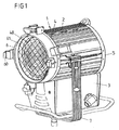
図1は、正面斜視図において、ランプハウジング2およびベーストレイ3よりなるプロジェクタハウジング1を備えたプロジェクタを示している。ランプハウジング2は、通常アルミニウム圧力ダイカストから製造された正面部4および背面部5を有している。正面部4は、正面レンズ40を含み、レンズマウント或いはアタッチメント6に接続される。アタッチメント6は、拡散板、フィルターディスク、保護ディスクなどのアタッチメント要素を受けるために、外周にわたって均等に配置された四つの保持用つめ60を含んでいるとともに、クランプ装置(さらに詳細には記述されない)を通してランプハウジング2へ接続される。プロジェクタを構成してプロジェクタを立たせる或いは吊るすことができるように、プロジェクタハウジング1をスタンド或いはリングに接続するために、保持用ブラケットがブラケットリンケージを通してランプハウジング2に接続される。図3における断面表示に対応して、ランプハウジング2は、ランプ或いはバーナー8およびレフレクタ9を囲んでいる。リフレクタ9は、ランプ或いはバーナー8によって放出される光ビームを図1による正面レンズ40の方向に反射するものである。
FIG. 1 shows a projector including a projector housing 1 including a
図1〜3、5および6にしたがい、ランプハウジング2は、ジャケットフローガイド板20および複数の冷却ダクト21〜26を含んでいる。冷却ダクト21〜26は、ジャケットフローガイド板20の周りに配置され、プロジェクタの光軸に平行に延び、ならびに、熱放出領域を増大させるために、変形されているが必ずしもうね模様のつかない外面を有している。冷却ダクト21〜26は、ギャップ10がジャケットフローガイド板20と冷却ダクト21〜26との間に形成されるように、ジャケットフローガイド板20からわずかに離間して配置される。
1-3, 5 and 6, the
熱の発散を増大させるために、ジャケットフローガイド板20は耐熱用黒ラッカーを塗布されるとともに、アルミニ鋳造合金或いは圧力ダイカスト合金からなることが好ましい。変形として、ジャケットフローガイド板20は、低反射率を有するしっかりと付着するセラミックコートを備えることができる。このコートは、耐熱性を増大させるため、プラズマ−化学作用による仕上げ工程において施される。このプラズマ−化学作用による工程は、特定の水性有機電解液内で行われる。この電解液の中で、ジャケットフローガイド板20は、アノードとして接続され、その結果、電解液中で生成される酸素プラズマの影響下においてジャケットフローガイド板20の表面上で金属が部分的に溶解して、良好な散乱特性を有するしっかりと付着する酸化セラミック/金属化合物がジャケットフローガイド板20上に生成される。
In order to increase heat dissipation, the jacket
ジャケットフローガイド板20は、ベーストレイ3の方向に開いており、図3における断面表示にしたがい、オメガ型の断面形を有している。ジャケットフローガイド板20は、ベーストレイ3の向かいに位置する表面において、複数の第一の開口部11、12、13(図3の断面および図5にしたがった縦断面の双方から推測することができる)を有している。これらの開口部は、隣接して順にプロジェクタの光軸方向に配置されるとともに、ギャップ10の間隔をあけて外側表面上に位置する冷却ダクト22、23、24、25に向かい合って配置される。
The jacket flow
第二の開口部14〜19は、冷却ダクト21〜26間、および外周方向においては冷却ダクト21〜26とベーストレイ3との間に形成される。より冷たい周囲の空気は第二の開口部を通して流れ入り、熱せられた空気は流れ出る。
The
図3による断面表示において矢印が象徴的に描かれており、この矢印は、ジャケットフローガイド板20の内部および外面における異なる空気の流れを特徴付けている。より冷たい外部の空気は、ベーストレイ3の空気入口開口部(より詳細には図示されない)を通してベーストレイ3を通るとともに、プロジェクタのイグナイタ、電気ケーブルおよび制御要素のようなベーストレイ3内に位置する電気電子部品によってそこに放出される熱を、例えば、ジャケットフローガイド板によって閉じられるランプハウジングの内部空間200へと導く。ランプ或いはバーナー8によって放出される熱放射は、循環する内部の流れすなわち第一の対流の流れK1を、ランプハウジング2のジャケットフローガイド板20の内部空間200においてさらに加熱するとともに、熱の一部をジャケットフローガイド板20へと、およびジャケットフローガイド板20の上部領域において配置された第一の開口部11、12、13を通して、ジャケットフローガイド20と冷却ガイド21〜26との間に形成されたギャップ10へと移動させる。
In the cross-sectional representation according to FIG. 3, arrows are symbolically drawn which characterize the different air flows in and on the jacket
外側の対流の流れすなわち第二の対流の流れK2のための空気は、外周方向において、外側の冷却ダクト21、26とベーストレイ3との間に形成された開口部14、19を通して吸い込まれる。対流の流れK2は、ジャケットフローガイド板20の周りに導かれて、熱負荷を部分的に冷却ダクト21〜26へ発散させるとともに、第二の開口部15、16、17、18を通して周囲へと発散させる。
The air for the outer convection flow, ie the second
冷却空気の流れK3は、ジャケットフローガイド板20の内部におよびジャケットフローガイド板20の周りに導かれる、内部および外部の対流の流れすなわち第一および第二の対流の流れK1およびK2に垂直に、冷却ダクト21〜26へと導く。これらの冷却ダクトは、図4にしたがい、冷却ダクト21から26の正面冷却ダクト開口部41〜46を通して導かれるとともに、図2にしたがい、背面冷却ダクト開口部51〜56を通して導かれる。冷却ダクト21〜26を通して導かれる冷却空気の流れK3は、プロジェクタが下方に傾いた場合は、入口開口部としての正面冷却ダクト開口部41〜46から、出口開口部としての背面冷却ダクト開口部51〜56へと方向付けられ、プロジェクタが上方に向けられた場合は、入口開口部としての背面冷却ダクト開口部51〜56から、出口開口部としての正面冷却ダクト開口部41〜45へと方向付けられる。
The cooling air flow K3 is perpendicular to the internal and external convection flows, ie the first and second convection flows K1 and K2, which are guided into and around the jacket
その上、ジャケットフローガイド板20の外側に導かれる外側の対流の流れK2は開口部50、57、58、59を通して背面部5によって周囲に流され、プロジェクタが傾く場合は、開口部50、57、58、59はプロジェクタハウジング1の背面部5において背面部5の外周上に配置が可能である。
In addition, the outer convection flow K2 guided to the outside of the jacket
さらに、覆われた空気出口スリット501、502、503は、背面部5の中央部の領域に用意することができる。ランプハウジング2の内部空間200、すなわちジャケットフローガイド板20内部に位置する熱せられた空気は、これらのスリットを通して、特にプロジェクタが傾いたときに、発散させることができる。
Further, the covered air outlet slits 501, 502, and 503 can be prepared in the central region of the
上記に言及された国際公開第2004/029507号にしたがって、ベーストレイ3上の側面に配置された冷却ダクトを提供するとともに、対流の流れのための目標とする空気の流れ導入用の直線的或いは曲面的フィンを提供することも、本発明の範囲内にある。
In accordance with the above-mentioned WO 2004/029507, a cooling duct arranged on the side surface on the
符号の一覧
1 プロジェクタハウジング
2 ランプハウジング
3 ベーストレイ
4 正面部
5 背面部
6 アタッチメント
7 保持用ブラケット
8 ランプ或いはバーナー
9 リフレクタ
10 ギャップ
11−13 第一の開口部
14−19 第二の開口部
20 ジャケットフローガイド板
21−26 冷却ダクト
40 正面レンズ
41−46 正面開口部
51−59 背面開口部
60 保持用つめ
200 内部空間
501−503 空気出口スリット
K1 第一の対流の流れ
K2 第二の対流の流れ
K3 冷却空気の流れ
Reference List 1
上記に言及された国際公開第2004/029507号にしたがって、ベーストレイ3上の側面に配置された冷却ダクトを提供するとともに、対流の流れのための目標とする空気の流れ導入用の直線的或いは曲面的フィンを提供することも、本発明の範囲内にある。
ここで、実施形態に記載された発明のうちで特許請求の範囲には記載されていない発明を以下に列挙する。
(1)請求項2に記載された発明において、
冷却ダクト(21〜26)はジャケットフローガイド板(20)から半径方向にわずかに離間して配置され、
第二の対流の流れ(K2)は、ジャケットフローガイド板(20)と冷却ダクト(21〜26)との間に形成されたギャップ(10)を通して流れるように構成されている冷却システム。
(2)請求項2に記載された発明において、
第二の開口部(14〜19)は、ランプハウジング(2)の正面から背面へ貫通するように、光軸にほぼ平行に延びるように構成されている冷却システム。
(3)請求項2に記載された発明において、
第一および第二の開口部(11〜13;14〜19)は、ランプハウジング(2)の周方向において互いに位置ずれして配置されるように構成されている冷却システム。
(4)請求項2に記載された発明において、
冷却ダクト(21〜26)はランプハウジング(2)の正面および背面において冷却ダクト開口部(41〜46;51〜56)を形成するように構成されている冷却システム。
In accordance with the above-mentioned WO 2004/029507, a cooling duct arranged on the side surface on the
Here, among the inventions described in the embodiments, the inventions not described in the claims are listed below.
(1) In the invention described in
The cooling ducts (21-26) are arranged slightly spaced radially from the jacket flow guide plate (20);
A cooling system configured to cause the second convective flow (K2) to flow through a gap (10) formed between the jacket flow guide plate (20) and the cooling ducts (21-26).
(2) In the invention described in
The second opening (14-19) is a cooling system configured to extend substantially parallel to the optical axis so as to penetrate from the front to the back of the lamp housing (2).
(3) In the invention described in
The cooling system configured such that the first and second openings (11 to 13; 14 to 19) are arranged to be displaced from each other in the circumferential direction of the lamp housing (2).
(4) In the invention described in
A cooling system in which the cooling ducts (21-26) are configured to form cooling duct openings (41-46; 51-56) at the front and back of the lamp housing (2).
Claims (14)
ランプハウジング(2)の周りであって、少なくとも部分的に周方向に循環する第二の対流の流れ(K2)のための第一の冷却デバイス(11〜20)と、
第二の対流の流れ(K2)にほぼ垂直に導かれるとともにプロジェクタの光軸に平行に流れる冷却空気の流れ(K3)のための第二の冷却デバイス(21〜26)とを特徴とする冷却システム。 A first light is conducted into the projector housing base tray and lamp housing by the light source and / or optical components or electrical and electronic components through which current flows. A projector cooling system for diverging with convection flow,
A first cooling device (11-20) for a second convection flow (K2) around the lamp housing (2) and at least partially circumferentially circulated;
Cooling characterized by a second cooling device (21-26) for a cooling air flow (K3) that is guided substantially perpendicular to the second convection flow (K2) and parallel to the optical axis of the projector system.
第一の対流の流れ(K1)は前記ジャケットフローガイド板の内部空間(200)へ導かれるとともに、第二の対流の流れ(K2)は前記ジャケットフローガイド板の周りに流れることを特徴とする請求項1に記載の冷却システム。 The first cooling device (11-20) has a jacket flow guide plate (20) arranged in the lamp housing (2),
The first convection flow (K1) is guided to the inner space (200) of the jacket flow guide plate, and the second convection flow (K2) flows around the jacket flow guide plate. The cooling system according to claim 1.
前記冷却ダクトは、前記冷却ダクトがプロジェクタの光軸に平行に延びるように、ジャケットフローガイド板(20)の周りであってこのジャケットフローガイド板から半径方向に離間してランプハウジング(2)内に配置されるとともに、冷却空気の流れ(K3)をプロジェクタハウジング(1)の長手方向に導くことを特徴とする請求項1又は2に記載の冷却システム。 Said second cooling device has cooling ducts (21-26);
The cooling duct is disposed around the jacket flow guide plate (20) and spaced radially from the jacket flow guide plate so that the cooling duct extends parallel to the optical axis of the projector. The cooling system according to claim 1 or 2, characterized in that the cooling air flow (K3) is guided in the longitudinal direction of the projector housing (1).
前記リフレクタは、光源(8)によって放出された光ビームをランプハウジング(2)の光出口開口部へ反射させるものであり、この光出口開口部は透明プレート(40)に覆われており、
重力の方向であってランプハウジング(2)の下方に配置されるほぼ立方形或いは多角形のベーストレイ(3)内に、イグナイタ、ケーブルリード線などのような電気電子部品が配置されていることを特徴とする請求項1から12の少なくとも一項に記載の冷却システム。 A light source (8) and a reflector (9) are arranged in a substantially cylindrical lamp housing (2) consisting of a jacket flow guide plate (20) and cooling ducts (21-26),
The reflector reflects the light beam emitted by the light source (8) to the light exit opening of the lamp housing (2), and the light exit opening is covered by the transparent plate (40),
Electrical and electronic parts such as igniters and cable leads are arranged in a substantially cubic or polygonal base tray (3) arranged in the direction of gravity and below the lamp housing (2). The cooling system according to at least one of claims 1 to 12.
ベーストレイ(3)内で前記機能要素によって熱せられた空気は、ベーストレイ(3)の上に配置されたランプハウジング(2)のジャケットフローガイド板(20)の内部空間(200)へ導かれることを特徴とする請求項13に記載の冷却システム。 The base tray (3) has an air inlet opening for cooling air;
The air heated by the functional element in the base tray (3) is guided to the internal space (200) of the jacket flow guide plate (20) of the lamp housing (2) disposed on the base tray (3). The cooling system according to claim 13.
Applications Claiming Priority (3)
| Application Number | Priority Date | Filing Date | Title |
|---|---|---|---|
| DE202005013244U DE202005013244U1 (en) | 2005-08-18 | 2005-08-18 | Cooling system for floodlight, has sheet metal cladding with circumferentially spaced openings provided about lamp housing and enclosed within circumferential array of cooling ducts defining another set of openings |
| DE202005013244.6 | 2005-08-18 | ||
| PCT/EP2006/008181 WO2007020108A1 (en) | 2005-08-18 | 2006-08-18 | Cooling system for a headlight |
Publications (2)
| Publication Number | Publication Date |
|---|---|
| JP2009505362A true JP2009505362A (en) | 2009-02-05 |
| JP4700734B2 JP4700734B2 (en) | 2011-06-15 |
Family
ID=35483660
Family Applications (1)
| Application Number | Title | Priority Date | Filing Date |
|---|---|---|---|
| JP2008526454A Expired - Fee Related JP4700734B2 (en) | 2005-08-18 | 2006-08-18 | Cooling system for projector |
Country Status (5)
| Country | Link |
|---|---|
| US (1) | US7857491B2 (en) |
| EP (1) | EP1915569B1 (en) |
| JP (1) | JP4700734B2 (en) |
| DE (2) | DE202005013244U1 (en) |
| WO (1) | WO2007020108A1 (en) |
Families Citing this family (7)
| Publication number | Priority date | Publication date | Assignee | Title |
|---|---|---|---|---|
| DE202006017131U1 (en) * | 2006-10-12 | 2007-01-25 | Arnold & Richter Cine Technik Gmbh & Co. Betriebs Kg | Floodlight for illuminating in films, studios, events and theaters has electrical connection that is rotationally arranged on the spotlight housing |
| WO2009113818A2 (en) * | 2008-03-12 | 2009-09-17 | Kmw Inc. | Enclosure device of wireless communication apparatus |
| FR2937403B1 (en) * | 2008-10-17 | 2013-05-03 | Rve Technologie | LIGHTING PROJECTOR WITH ENERGY DRAINAGE DEVICE |
| CN102748670A (en) * | 2012-06-21 | 2012-10-24 | 上海半导体照明工程技术研究中心 | LED (Light-Emitting Diode) projection lamp |
| CN103438385A (en) * | 2013-03-25 | 2013-12-11 | 郑运婷 | LED (light-emitting diode) streetlamp |
| CN103939809B (en) * | 2014-05-08 | 2017-02-15 | 湖州积微电子科技有限公司 | Projection lamp convenient to install |
| USD848054S1 (en) * | 2016-06-01 | 2019-05-07 | Fuzhou F&V Photographic Equipment Co., Ltd. | Spotlight |
Citations (4)
| Publication number | Priority date | Publication date | Assignee | Title |
|---|---|---|---|---|
| US4546420A (en) * | 1984-05-23 | 1985-10-08 | Wheeler Industries, Ltd. | Air cooled light fixture with baffled flow through a filter array |
| WO1993020384A2 (en) * | 1992-03-31 | 1993-10-14 | Phoenix Products Company, Inc. | Outdoor framing projector |
| JPH06162805A (en) * | 1992-09-04 | 1994-06-10 | Barry Wright Inc | Lighting fixture |
| JP2002258407A (en) * | 2001-02-14 | 2002-09-11 | Acer Communications & Multimedia Inc | Light emission device with high heat diffusion efficiency |
Family Cites Families (10)
| Publication number | Priority date | Publication date | Assignee | Title |
|---|---|---|---|---|
| US1758290A (en) * | 1928-06-29 | 1930-05-13 | Mccormack William Eugene | Lantern body for cinematograph and other projection apparatus |
| GB1201894A (en) | 1969-05-16 | 1970-08-12 | Berkey Technical U K Ltd | Improvements in or relating to studio lighting |
| US4658338A (en) * | 1985-07-03 | 1987-04-14 | Quartzcolor Ianiro S.P.A. | Lighting projectors with an intensified and accelerated air flow cooling system for photographic and motion picture studios |
| US4925295A (en) * | 1986-03-17 | 1990-05-15 | Casio Computer Co., Ltd. | Projection display apparatus |
| US5367444A (en) * | 1990-09-06 | 1994-11-22 | Vari-Lite Inc. | Thermal management techniques for lighting instruments |
| US5099399A (en) * | 1991-04-08 | 1992-03-24 | Miller Jack V | High efficiency fiber optics illuminator with thermally controlled light guide bushing |
| US5172975A (en) * | 1992-04-27 | 1992-12-22 | Mole-Richardson Co. | Light assembly with ventilated housing |
| DE19509480A1 (en) | 1995-03-16 | 1996-09-19 | Ansorg Gmbh | Lamp for office and room wall and ceiling lights |
| JP3376540B2 (en) * | 1997-09-01 | 2003-02-10 | 株式会社日立製作所 | LCD projector |
| DE20214874U1 (en) | 2002-09-20 | 2003-11-06 | Arnold & Richter Kg | headlights |
-
2005
- 2005-08-18 DE DE202005013244U patent/DE202005013244U1/en not_active Expired - Lifetime
-
2006
- 2006-08-18 DE DE502006005927T patent/DE502006005927D1/en active Active
- 2006-08-18 US US11/990,565 patent/US7857491B2/en not_active Expired - Fee Related
- 2006-08-18 EP EP06776971A patent/EP1915569B1/en not_active Expired - Fee Related
- 2006-08-18 WO PCT/EP2006/008181 patent/WO2007020108A1/en active Application Filing
- 2006-08-18 JP JP2008526454A patent/JP4700734B2/en not_active Expired - Fee Related
Patent Citations (4)
| Publication number | Priority date | Publication date | Assignee | Title |
|---|---|---|---|---|
| US4546420A (en) * | 1984-05-23 | 1985-10-08 | Wheeler Industries, Ltd. | Air cooled light fixture with baffled flow through a filter array |
| WO1993020384A2 (en) * | 1992-03-31 | 1993-10-14 | Phoenix Products Company, Inc. | Outdoor framing projector |
| JPH06162805A (en) * | 1992-09-04 | 1994-06-10 | Barry Wright Inc | Lighting fixture |
| JP2002258407A (en) * | 2001-02-14 | 2002-09-11 | Acer Communications & Multimedia Inc | Light emission device with high heat diffusion efficiency |
Also Published As
| Publication number | Publication date |
|---|---|
| EP1915569A1 (en) | 2008-04-30 |
| WO2007020108A1 (en) | 2007-02-22 |
| EP1915569B1 (en) | 2010-01-13 |
| JP4700734B2 (en) | 2011-06-15 |
| DE202005013244U1 (en) | 2005-12-01 |
| US7857491B2 (en) | 2010-12-28 |
| US20090133857A1 (en) | 2009-05-28 |
| DE502006005927D1 (en) | 2010-03-04 |
Similar Documents
| Publication | Publication Date | Title |
|---|---|---|
| JP4700734B2 (en) | Cooling system for projector | |
| US8118462B2 (en) | Automotive lamp | |
| US5138541A (en) | Lamp with ventilated housing | |
| US7559676B2 (en) | Light source module | |
| JP6199970B2 (en) | Heat dissipation structure with segmented chimney structure | |
| JP5499475B2 (en) | Lamp device and lighting device | |
| JP6125675B2 (en) | Lighting device and lighting fixture | |
| JP4661740B2 (en) | LED lights for vehicles | |
| US9121589B2 (en) | Projector | |
| JP5847574B2 (en) | High-speed illuminator | |
| JP4333375B2 (en) | Recessed ceiling fluorescent lighting | |
| WO2011107979A1 (en) | Led lamp fitting having an integral cooling fan | |
| WO2018230347A1 (en) | Led lamp | |
| TWI407240B (en) | Heat dissipation structure for dmd and projector use same | |
| JP2009076338A (en) | Lamp | |
| JP3221131U (en) | Integrated LED car light | |
| KR101883170B1 (en) | Led light device for medical usage improving radiant heatcapacity | |
| JP6849943B2 (en) | Lighting device | |
| JP6584205B2 (en) | Lighting device | |
| JP2023134081A (en) | Illuminating tool and illuminating device comprising illuminating tool | |
| JP2001229701A (en) | Illumination device | |
| JP6118665B2 (en) | Heat sink device | |
| JP2015212997A (en) | Lighting device | |
| JP2008186636A (en) | Led illumination unit, and illumination fixture using it | |
| JP3097333U (en) | LED lamp |
Legal Events
| Date | Code | Title | Description |
|---|---|---|---|
| A131 | Notification of reasons for refusal |
Free format text: JAPANESE INTERMEDIATE CODE: A131 Effective date: 20101005 |
|
| A521 | Written amendment |
Free format text: JAPANESE INTERMEDIATE CODE: A523 Effective date: 20101125 |
|
| A01 | Written decision to grant a patent or to grant a registration (utility model) |
Free format text: JAPANESE INTERMEDIATE CODE: A01 Effective date: 20110208 |
|
| A61 | First payment of annual fees (during grant procedure) |
Free format text: JAPANESE INTERMEDIATE CODE: A61 Effective date: 20110304 |
|
| R250 | Receipt of annual fees |
Free format text: JAPANESE INTERMEDIATE CODE: R250 |
|
| R250 | Receipt of annual fees |
Free format text: JAPANESE INTERMEDIATE CODE: R250 |
|
| LAPS | Cancellation because of no payment of annual fees |