EP1545121A1 - Bildcodierungseinrichtung, bildcodierungsverfahren und bildverarbeitungseinrichtung - Google Patents
Bildcodierungseinrichtung, bildcodierungsverfahren und bildverarbeitungseinrichtung Download PDFInfo
- Publication number
- EP1545121A1 EP1545121A1 EP03741377A EP03741377A EP1545121A1 EP 1545121 A1 EP1545121 A1 EP 1545121A1 EP 03741377 A EP03741377 A EP 03741377A EP 03741377 A EP03741377 A EP 03741377A EP 1545121 A1 EP1545121 A1 EP 1545121A1
- Authority
- EP
- European Patent Office
- Prior art keywords
- tile
- unit
- distortion
- coefficient
- category
- Prior art date
- Legal status (The legal status is an assumption and is not a legal conclusion. Google has not performed a legal analysis and makes no representation as to the accuracy of the status listed.)
- Withdrawn
Links
Images


Classifications
-
- H—ELECTRICITY
- H04—ELECTRIC COMMUNICATION TECHNIQUE
- H04N—PICTORIAL COMMUNICATION, e.g. TELEVISION
- H04N19/00—Methods or arrangements for coding, decoding, compressing or decompressing digital video signals
- H04N19/10—Methods or arrangements for coding, decoding, compressing or decompressing digital video signals using adaptive coding
- H04N19/102—Methods or arrangements for coding, decoding, compressing or decompressing digital video signals using adaptive coding characterised by the element, parameter or selection affected or controlled by the adaptive coding
- H04N19/103—Selection of coding mode or of prediction mode
- H04N19/105—Selection of the reference unit for prediction within a chosen coding or prediction mode, e.g. adaptive choice of position and number of pixels used for prediction
-
- H—ELECTRICITY
- H03—ELECTRONIC CIRCUITRY
- H03M—CODING; DECODING; CODE CONVERSION IN GENERAL
- H03M7/00—Conversion of a code where information is represented by a given sequence or number of digits to a code where the same, similar or subset of information is represented by a different sequence or number of digits
- H03M7/30—Compression; Expansion; Suppression of unnecessary data, e.g. redundancy reduction
- H03M7/40—Conversion to or from variable length codes, e.g. Shannon-Fano code, Huffman code, Morse code
-
- H—ELECTRICITY
- H04—ELECTRIC COMMUNICATION TECHNIQUE
- H04N—PICTORIAL COMMUNICATION, e.g. TELEVISION
- H04N19/00—Methods or arrangements for coding, decoding, compressing or decompressing digital video signals
- H04N19/10—Methods or arrangements for coding, decoding, compressing or decompressing digital video signals using adaptive coding
- H04N19/102—Methods or arrangements for coding, decoding, compressing or decompressing digital video signals using adaptive coding characterised by the element, parameter or selection affected or controlled by the adaptive coding
- H04N19/115—Selection of the code volume for a coding unit prior to coding
-
- H—ELECTRICITY
- H04—ELECTRIC COMMUNICATION TECHNIQUE
- H04N—PICTORIAL COMMUNICATION, e.g. TELEVISION
- H04N19/00—Methods or arrangements for coding, decoding, compressing or decompressing digital video signals
- H04N19/10—Methods or arrangements for coding, decoding, compressing or decompressing digital video signals using adaptive coding
- H04N19/134—Methods or arrangements for coding, decoding, compressing or decompressing digital video signals using adaptive coding characterised by the element, parameter or criterion affecting or controlling the adaptive coding
- H04N19/136—Incoming video signal characteristics or properties
- H04N19/14—Coding unit complexity, e.g. amount of activity or edge presence estimation
-
- H—ELECTRICITY
- H04—ELECTRIC COMMUNICATION TECHNIQUE
- H04N—PICTORIAL COMMUNICATION, e.g. TELEVISION
- H04N19/00—Methods or arrangements for coding, decoding, compressing or decompressing digital video signals
- H04N19/10—Methods or arrangements for coding, decoding, compressing or decompressing digital video signals using adaptive coding
- H04N19/134—Methods or arrangements for coding, decoding, compressing or decompressing digital video signals using adaptive coding characterised by the element, parameter or criterion affecting or controlling the adaptive coding
- H04N19/146—Data rate or code amount at the encoder output
- H04N19/147—Data rate or code amount at the encoder output according to rate distortion criteria
-
- H—ELECTRICITY
- H04—ELECTRIC COMMUNICATION TECHNIQUE
- H04N—PICTORIAL COMMUNICATION, e.g. TELEVISION
- H04N19/00—Methods or arrangements for coding, decoding, compressing or decompressing digital video signals
- H04N19/10—Methods or arrangements for coding, decoding, compressing or decompressing digital video signals using adaptive coding
- H04N19/169—Methods or arrangements for coding, decoding, compressing or decompressing digital video signals using adaptive coding characterised by the coding unit, i.e. the structural portion or semantic portion of the video signal being the object or the subject of the adaptive coding
- H04N19/17—Methods or arrangements for coding, decoding, compressing or decompressing digital video signals using adaptive coding characterised by the coding unit, i.e. the structural portion or semantic portion of the video signal being the object or the subject of the adaptive coding the unit being an image region, e.g. an object
- H04N19/174—Methods or arrangements for coding, decoding, compressing or decompressing digital video signals using adaptive coding characterised by the coding unit, i.e. the structural portion or semantic portion of the video signal being the object or the subject of the adaptive coding the unit being an image region, e.g. an object the region being a slice, e.g. a line of blocks or a group of blocks
-
- H—ELECTRICITY
- H04—ELECTRIC COMMUNICATION TECHNIQUE
- H04N—PICTORIAL COMMUNICATION, e.g. TELEVISION
- H04N19/00—Methods or arrangements for coding, decoding, compressing or decompressing digital video signals
- H04N19/10—Methods or arrangements for coding, decoding, compressing or decompressing digital video signals using adaptive coding
- H04N19/169—Methods or arrangements for coding, decoding, compressing or decompressing digital video signals using adaptive coding characterised by the coding unit, i.e. the structural portion or semantic portion of the video signal being the object or the subject of the adaptive coding
- H04N19/17—Methods or arrangements for coding, decoding, compressing or decompressing digital video signals using adaptive coding characterised by the coding unit, i.e. the structural portion or semantic portion of the video signal being the object or the subject of the adaptive coding the unit being an image region, e.g. an object
- H04N19/176—Methods or arrangements for coding, decoding, compressing or decompressing digital video signals using adaptive coding characterised by the coding unit, i.e. the structural portion or semantic portion of the video signal being the object or the subject of the adaptive coding the unit being an image region, e.g. an object the region being a block, e.g. a macroblock
-
- H—ELECTRICITY
- H04—ELECTRIC COMMUNICATION TECHNIQUE
- H04N—PICTORIAL COMMUNICATION, e.g. TELEVISION
- H04N19/00—Methods or arrangements for coding, decoding, compressing or decompressing digital video signals
- H04N19/60—Methods or arrangements for coding, decoding, compressing or decompressing digital video signals using transform coding
- H04N19/63—Methods or arrangements for coding, decoding, compressing or decompressing digital video signals using transform coding using sub-band based transform, e.g. wavelets
- H04N19/64—Methods or arrangements for coding, decoding, compressing or decompressing digital video signals using transform coding using sub-band based transform, e.g. wavelets characterised by ordering of coefficients or of bits for transmission
- H04N19/645—Methods or arrangements for coding, decoding, compressing or decompressing digital video signals using transform coding using sub-band based transform, e.g. wavelets characterised by ordering of coefficients or of bits for transmission by grouping of coefficients into blocks after the transform
-
- H—ELECTRICITY
- H04—ELECTRIC COMMUNICATION TECHNIQUE
- H04N—PICTORIAL COMMUNICATION, e.g. TELEVISION
- H04N19/00—Methods or arrangements for coding, decoding, compressing or decompressing digital video signals
- H04N19/90—Methods or arrangements for coding, decoding, compressing or decompressing digital video signals using coding techniques not provided for in groups H04N19/10-H04N19/85, e.g. fractals
- H04N19/91—Entropy coding, e.g. variable length coding [VLC] or arithmetic coding
-
- H—ELECTRICITY
- H04—ELECTRIC COMMUNICATION TECHNIQUE
- H04N—PICTORIAL COMMUNICATION, e.g. TELEVISION
- H04N19/00—Methods or arrangements for coding, decoding, compressing or decompressing digital video signals
- H04N19/10—Methods or arrangements for coding, decoding, compressing or decompressing digital video signals using adaptive coding
- H04N19/134—Methods or arrangements for coding, decoding, compressing or decompressing digital video signals using adaptive coding characterised by the element, parameter or criterion affecting or controlling the adaptive coding
- H04N19/146—Data rate or code amount at the encoder output
Definitions
- the present invention relates to the image coding device, the image coding method, and the image processing device, for dividing an input image into tiles of the pre-determined size, for transforming an image signal included in the individual tile to the frequency component, for quantizing the transformation coefficient obtained, for entropy coding the quantized coefficient, at the same time, for calculating a quantized distortion, and controlling a code amount of the coded data which is entropy coded using the quantized distortion.
- the point object extending method is jointly used to control the linear distortion existing at the tile border, in addition to the object extending method defined in JPEG2000.
- the two extending methods are controlled by switching from one to the other, such that it is necessary to imbed in the coded data which extending method is being used.
- This does not only leads to a problem of the increased amount of coded data, but it also causes a problem of failing to maintain the compatibility since it exceeds the range of the standard of the JPEG2000.
- the distortion of the tile border is conspicuous in the area where there is no object such as background area and the area where a texture is less.
- a small fluctuation signal of the level close to the noise is included barely as the texture (hereinafter referred to as fluctuation texture).
- fluctuation texture a small fluctuation signal of the level close to the noise
- the rate control function forming the final code data
- the sub band that corresponds to this fluctuation texture is detected, the high weight is set to that sub band by using the frequency weighting(frequency Weighting), and barely existing texture is reconstructed, and the tile border is likely be controlled by the dithering effect.
- this method adapts the identical processing to all tiles, even setting a high weight to the tile that does not originally require the high weight setting.
- a relatively low weight is set to the area of visual importance, and the image quality of that part may likely to decrease.
- the same frequency weighting processing is applied to all tiles, perhaps the tile border may be controlled, but, there is a problem that image quality degradation may occur at other visually important areas.
- JPEG2000 prepares a rate control function which controls the final amount of coded data within a fixed range, and supplies the highest image quality based on the mean squared error within the fixed range.
- a rate control function which controls the final amount of coded data within a fixed range, and supplies the highest image quality based on the mean squared error within the fixed range.
- the sub band of the wavelet transformation area that corresponds to this texture is detected, the weight of that sub band is set high, and a satisfactory texture is reconstructed.
- this method adapts the identical processing to all tiles, even setting a high weight to the tile that does not originally require the high weight setting.
- a relatively low weight is set to the area of visual importance, and the image quality of that part may likely to decrease.
- the same frequency weighting processing is applied equally to all tiles in order to improve the reconstruction of fine texture such as skin of a person, perhaps the high quality may be possible at the part of the skin of person, but there is a problem of image quality degradation occurring at other visually important areas.
- the present invention attempts to solve these problems.
- the present invention aims to supply the image coding device, the image coding method, and the image processing device, in the case of coding an input image by tile division, for flexibly controlling the coding rate of the image signal depending on the tiles, for allowing a finer image adjustment responsive to the characteristic of each tile, and for supplying a satisfactory overall playback image.
- an image coding device for dividing an input signal into tiles of a certain size, for transforming an image signal included in each tile to a frequency component and obtaining a transformation coefficient, for quantizing an obtained transformation coefficient to a qunatized coefficient, for entropy coding the qunatized coefficient, for calculating a quantized distortion upon quantizing of the transformation coefficient, and for controlling a code amount of a coded data obtained by the entropy coding using the quantized distortion, which comprises a tile classifying unit for classifying each tile based on its characteristic into a plurality of categories by referring to the transformation coefficient, and for outputting a classified result; a weighting unit for weighting the quantized distortion based on an output of the tile classifying unit; and a rate controlling unit for controlling the code amount of a code data obtained by the entropy coding, based on the quantized distortion weighted by the weighting unit.
- an image coding method for dividing an input signal into tiles of a certain size, for transforming an image signal included in each tile to a frequency component and obtaining a transformation coefficient, for quantizing an obtained transformation coefficient to a qunatized coefficient, for entropy coding the qunatized coefficient, for calculating a quantized distortion upon quantizing of the transformation coefficient, and for controlling a code amount of a coded data obtained by the entropy coding using the quantized distortion, comprises the steps of classifying each tile based on its characteristic into a plurality of categories by referring to the transformation coefficient and weighting the quantized distortion with a weight coefficient for each category; and controlling the code amount of a code data obtained by the entropy coding, based on the quantized distortion weighted with the weight coefficient.
- an image processing device comprises the image coding device of claim 1, for processing the coded data where the code amount is controlled by the image coding device.
- Fig. 1 shows a block chart of an image coding device of Embodiment 1.
- the reference numeral 101 denotes a color coordinates transforming unit for transforming the color spatial coordinates, from RGB signals to YCbCr and the like, as required.
- the reference numeral 102 denotes a tile dividing unit for dividing each color component signal into a plurality of rectangular shapes called tiles.
- the reference numeral 103 denotes a wavelet transforming unit for executing the two dimensional wavelet transformation.
- the reference numeral 104 denotes a quantization processing unit to quantize a wavelet transformation coefficient generated at the wavelet transforming unit based on a quantization step size being set.
- the reference numeral 105 denotes a coefficient modeling unit for modeling a quantized wavelet transformation coefficient for a binary arithmetic coding.
- the reference numeral 106 denotes an entropy coding unit for performing an entropy coding based on the arithmetic coding.
- the reference numeral 107 denotes a code memory for storing code data that is entropy coded.
- the reference numeral 108 denotes a distortion calculating unit for calculating a distortion in an unit of the entropy coding.
- the reference numeral 109 denotes a distortion memory for storing distortion data calculated at the distortion calculating unit 108.
- the reference numeral 110 denotes a multiplier for multiplying a desired weight coefficient and the distortion data output from the distortion memory 109.
- the reference numeral 111 denotes a complex tile deciding unit for deciding whether or not a tile is a complex tile including many complex textures based on the wavelet transformation coefficient of each tile.
- the reference numeral 112 denotes a tile classifying memory for storing an output of the complex tile deciding unit 111.
- the reference numeral 113 denotes a weight coefficient selecting unit, for selecting a corresponding weight coefficient from a plurality of weight coefficients that are being stored beforehand, based on an output of the tile classifying memory 112.
- the reference numeral 114 denotes a rate controlling unit for selecting a necessary data from the code data stored in the code memory 107 by considering a weighted distortion data output from the multiplier 110, and for controlling a rate so as to be within a target code amount being set.
- the reference numeral 301 denotes a tile classifying unit including the complex tile deciding unit 111.
- the weighting unit of the present invention is formed by the weight coefficient selecting unit 113 and the multiplier 110.
- the color spatial coordinates transformation is executed at the color coordinates transforming unit 101, as required.
- a transformation of the luminance signal (Y) and the color difference signals (Cb and Cr) is carried out.
- the RCT transformation having no loss is carried out.
- this color coordinates transforming unit is bypassed when a monochrome image signal is being input.
- each color component signal input from the color coordinates transforming unit 101 is divided into a plurality of rectangular areas called tiles. In the later processing, this tile is treated as one image.
- one tile is regarded as one image, and the two dimensional wavelet transformation is executed, and then a band division into a plurality of sub bands is executed.
- the two dimensional wavelet transformation is actualized here as combination of one dimensional wavelet transformations. In other words, they are a process where one dimensional wavelet transformation of horizontal direction is consecutively done in every line, and a process where one dimensional wavelet transformation of vertical direction is consecutively done in every line.
- Fig. 2 shows an outline example of configuration and operation of the wavelet transforming unit 103.
- Fig. 2(a) shows an example of the configuration of one dimensional wavelet transformation component in the wavelet transforming unit 103, and one dimensional wavelet transformation comprises a low pass filter, a high pass filter, and down samplers, carrying pre-determined characteristics.
- the two dimensional wavelet transformation is actualized as combination of one dimensional wavelet transformations.
- a number of taps (coefficients) for these filter processing is 9 for lossy compression low pass filter, 7 for high pass filter, 5 for lossless compression low pass filter, and 3 for high pass filter.
- the wavelet transformation is executed recursively to the low area component (the LL component) in the horizontal and vertical directions.
- Each sub band that is formed by each recursive wavelet transformation is termed a resolution level and corresponds to the numbers stated before the LL, the HL, the LH, and the HH in the drawing. That is, the LL component of the lowest resolution always corresponds to the resolution level 0, and in contrast to this, the resolution level of the high pass components HL, LH, and HH of the highest resolution is identical to the number of times of wavelet transformation. In this example shown in the drawing, since the wavelet transformation is carried out twice, the resolution level of the highest resolution component becomes 2.
- the wavelet transformation coefficient is quantized based on the quantization step size which is being set for every sub band.
- each bit plane is divided into three kinds of coding passes (the significance pass, the refinement pass, and the cleanup pass).
- the context modeling of the respective coding passes is performed for the purpose of entropy coding.
- the arithmetic coding is done by the entropy coding unit 106.
- a coded data which is formed in the entropy coding unit 106 is once stored in the code memory 107.
- the distortion calculating unit 108 the distortion is calculated for each coding pass of each code block.
- Calculated distortion data is stored in the distortion memory 109,after attaching an index that can specify the color component, the tile number, the sub band, the code block, and the coding pass, to the calculated distortion data.
- an average power Pt is calculated using the equation (1) shown below.
- C (i, j) represents a transformation coefficient of the HH component at the position (i, j).
- Jmax represents a sample number in the horizontal direction of the HH component.
- Imax represents a sample number in the vertical direction.
- a certain threshold value Tp is set, and a category of a particular tile is decided, if it is the complex tile or the simple tile, in accordance to the decision equations shown below.
- Output of the complex tile deciding unit 111 is once stored in the tile classifying memory 112.
- the code data is stored in the code memory 107
- the distortion data is stored in the distortion memory 109
- the tile category is stored in the tile classifying memory 112, which are to be stored over all tiles.
- the rate control is executed in the rate controlling unit 114.
- the distortion data Di of each code pass is output from the distortion memory 109, depending on the index of the coding pass, the code block, the sub band, the tile number, and the color component, which are outputted from the rate controlling section 114.
- the weight coefficient selected by the weight coefficient selecting unit 113 is multiplied to the distortion data Di of each coding pass.
- the weight coefficient selecting unit 113 shall be described in detail with reference to Fig. 3.
- Fig. 3 shows the detailed configuration of the weight coefficient selecting unit 113 of Fig. 1.
- the reference numeral 201 denotes a weight coefficient register group for displaying a plurality of registers that store each of a plurality of weight coefficients respectively.
- the reference numeral 202 denotes a selecting unit for selecting the desired weight coefficient on the basis of the select signal out of the plurality of weight coefficients output from the weight coefficient register group 201. Operation shall be described hereinbelow.
- the tile category is input from the tile classifying memory 112 to the selecting unit 202 of the weight coefficient selecting unit 113, and the index which shows the sub band and the color component which the coding pass belongs to, the coding pass which presently has been about to be processed, are input from the rate controlling unit 114 to the selecting unit 202 of the weight coefficient selecting unit 113. Therefore, the selecting unit 202 selects the corresponding weight coefficient on the basis of these input select signals, and outputs the selected weight coefficient to the multiplier 110.
- the multiplier 110 as mentioned previously, the weight coefficient which is selected at the weight coefficient selecting unit 113 is multiplied to the distortion data Di of each coding pass, and output.
- data storing methods in the distortion memory 109, that in the tile classifying memory 112, and that in the weight coefficient register group 201 are respectively illustrated in the drawings of Fig. 4(a), (b), and (c).
- the weighted distortion Di of each coding pass is outputted from the multiplier 110 of Fig. 1 to the rate controlling unit 114.
- the rate controlling unit 114 performs rate controlling, that is, adjusts the code amount so that the data of the coded data from the code memory 107 can be under the target code size, based on the weighted distortion Di of each coding pass, which is input from the multiplier 110, and provides the highest image quality which can be reconstructed within that target code size.
- the distortion calculating unit 108 in parallel to the entropy coding process at the entropy coding unit 106, in the distortion calculating unit 108, the square mean of the error during quantization of each coding pass is calculated as the distortion. And the weight coefficient for each tile category is multiplied to this distortion, so in the rate controlling unit 114, in order for the distortion multiplied by this weight coefficient to become minimum, the coded data is selectively acquired in each coding pass , and the highest image quality at the target code amount is provided by trying to settle the total code amount within the target code size. Furthermore, in order to simultaneously satisfy the two conditions of smallest distortion and under the target code amount, the optimization calculation becomes necessary, but as mentioned previously, Lagrange's method of the undetermined multipliers is utilized.
- each tile is classified into two categories of the complex tile and the simple tile based on its characteristic. And, it becomes possible to set weight on every sub band to suit the respective tile categories. Because of this, in comparison to the conventional system of uniform weight setting over all tile, there is an advantage that a finer image quality adjustment becomes possible, due to the fact that flexibility of the image quality setting has improved.
- Fig. 5 shows a block chart of an image coding device of Embodiment 2.
- Fig. 5 note that there are blocks having identical reference numerals as Fig. 1, and the operation of these blocks are completely same as those explained in Embodiment 1.
- Fig. 5 from Fig. 1 are a tile classifying unit 301 and a weight coefficient selecting unit 302.
- This tile classifying unit 301 classifies into three categories based on the characteristic of each tile.
- the weight coefficient selecting unit 302 selects the desired weight coefficient among the weight coefficients corresponding to the three categories.
- tile classifying unit 301 is described in detail with reference to Fig. 6.
- Fig. 6 shows a detailed configuration of the tile classifying unit 301.
- the reference numeral 111 is identical to the complex tile deciding unit 111 of Fig. 1, which is a complex tile deciding unit for deciding whether or not a particular tile is the complex tile.
- the reference numeral 401 denotes an inclined tile deciding unit which decides whether or not a particular tile is the inclined tile.
- the reference numeral 402 denotes an integrated deciding unit for receiving the outputs of the complex tile deciding unit 111 and the inclined tile deciding unit 401, and for deciding whether or not a particular tile corresponds to one of the tile categories of the complex tile, the simple tile, and the inclined tile.
- the complex tile deciding unit 111 does the completely identical operation as the operation explained in Embodiment 1.
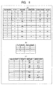
- Fig. 7 shows a detailed configuration of the inclined tile deciding unit 401.
- the reference numeral 501 denotes an auto-correlation calculating unit which calculates the auto-correlation coefficient of the desired sub band.
- the reference numeral 502 denotes a deciding unit for deciding whether or not a particular tile is the inclined tile based on the auto-correlation coefficient which is an output of the auto-correlation calculating unit 501.
- the auto-correlation calculating unit 501 calculates the auto-correlation coefficient At by using the equation (4) shown below, for the HH component having the resolution level n (the highest resolution) of the highest resolution in each tile.
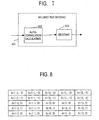
- At (x, y) represents the position of the auto-correlation coefficient of the position shown in Fig. 8.
- the deciding unit 502 decides whether or not a particular tile is the inclined tile having a strong correlation in the inclined direction, by using the auto-correlation-coefficient At (x, y). Firstly, among the 25 auto-correlation coefficients At (x, y), those that have a negative value is reset to 0. Sum 1 and sum 2 for the coefficient At (x, y) after reset are respectively calculated by using the following decider equations (5) and (6).
- the ratio between sum 1 and sum 2, and the threshold value Ta which is worked out from experiences such as experiments and simulations, are compared. For example, as shown below, if the ratio between sum 1 and sum 2 is greater than the threshold value Ta, then a particular tile is decided as the inclined tile. If the ratio between sum 1 and sum 2 is smaller than the threshold value Ta, then a particular tile is decided as the non-inclined tile. '
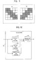
- Fig. 9 is a chart simply explaining which auto-correlation coefficients are summed for calculation of the sum 1 and the sum 2, respectively.
- a sum of the auto-correlation coefficients of the right side going down indicated by shade shows the sum 1.
- a sum of the auto-correlation coefficients of the right side going up indicated by shade shows the sum 2.
- the present decision if there is any deviation in one of the sum 1 or the sum 2, then it is decided as the inclined tile.
- the integrated deciding unit 402 receives the decision outputs of the complex tile deciding unit 111 and the inclined tile deciding unit 401. For example, as shown below, if there is no input of the decision output of the complex tile, the category is decided as the simple tile. And, if there is an input of the decision output of the complex tile, then depending on the availability of an input of the decision output of the inclined tile, the category is decided as the complex tile if there is no input of the inclined tile. The category is decided as the inclined tile if there is an input of the inclined tile. The integrated deciding unit 402 decides the category of a particular tile as either one of the complicated tile, the simple tile, and the inclined tile.
- a tile to be finally decided as the inclined tile has the condition that the average power of the HH component is relatively high.
- the weight coefficient selecting unit 302 of Embodiment 2 beforehand stores the weight coefficients of every sub band corresponding to the complex tile, the simple tile, and the inclined tile.
- the weight coefficient selecting unit 302 regards the tile category of the focussed tile from the tile classifying memory 112 and the index showing the color component and sub band where the coding pass belongs, the coding pass of which presently has been about to be processed, from the rate controlling unit 114, as the select signal. And the weight coefficient selecting unit 302 selects the weight coefficients of every sub band based on the select signal.
- the weight coefficient that corresponds to the distortion data outputted from the distortion memory 109 is selected in the weight coefficient selecting unit 302, and is output to the multiplier 110.
- the distortion data and the corresponding weight coefficient is multiplied, and after that, in the rate controlling unit 114, in the similar manner as Embodiment 1, the code amount of the coded data is controlled; namely, the rate control is performed.
- each tile is classified into three categories of the complex tile, the simple tile, and the inclined tile, based on its characteristic. And, it becomes possible to set weight to every sub band suitable for the respective tile categories. Because of this, similar to the case of Embodiment 1, in comparison to the conventional method of setting uniform weight over all tiles, since flexibility of the image quality setting has improved further, there is an effect that a finer image quality adjustment becomes possible.
- the basic configuration block diagram is identical to the one explained in Fig. 5 of Embodiment 2.
- the configuration of the tile classifying unit 301 of Fig. 5 is different in Embodiment 3. Specifically, a flesh color tile detection processing is newly added.
- the configuration and operation of the tile classifying unit of Embodiment 3 is described with reference to Fig. 10.
- Fig. 10 shows the detailed configuration of the tile deciding unit 301 of Embodiment 3.
- the reference numeral 111 denotes a complex tile deciding unit which is same as those shown in Figs. 1 and 6.
- the reference numeral 401 denotes a inclined tile deciding unit which is same as that shown in Fig. 6.
- the reference numeral 801 denotes a flesh color tile deciding unit for detecting whether or not a particular tile contains much flesh color.
- the reference numeral 802 denotes an integrated deciding unit for receiving the outputs of the complex tile deciding unit 111, the inclined tile deciding unit 401, and the flesh color tile deciding unit 801, and for deciding whether or not a particular tile corresponds to either one of the 4 categories which shall be described later in the specification.
- the flesh color tile deciding unit 801 detects whether or not each coefficient is the flesh color. Specifically, the RGB signals are converted to the signal of the HSL color coordinates system at the color coordinates transforming unit 101. When the 0LL component after the wavelet transformation is within the range of a certain threshold value, for all the color components of H (hue), S (chroma), L (lightness), it is decided as the flesh color. Provided that the upper and lower limits of the threshold values for the respective color components are designated as the subscripts max and min, then this decision can be indicated as follows.
- the flesh color tile deciding unit 801 counts the flesh color coefficients detected accordingly. If the count value is greater than the pre-determined threshold value, then the flesh color tile deciding unit decides it as the flesh color tile and outputs.
- the complex tile deciding unit 111 and the inclined tile deciding unit 401 operate in the likewise manner as the cases of Embodiments 1 and 2 described previously.
- the decision outputs of the complex tile deciding unit 111, the inclined tile deciding unit 401, and the flesh color tile deciding unit 801 are input.
- the integrated deciding unit 802 decides to which category a particular tile belongs among the complex tile, the simple tile, the inclined tile, and the flesh color tile , for example, in a following manner. In other words, if the decision output of the flesh color tile has been input, it is decided as the flesh color tile category. If the decision output of the flesh color tile has not been input, then depending on the availability of the input of the decision output of the complex tile, it is decided as the simple tile category if no decision output of the complex tile is being input.
- the decision output of the complex tile is being input, then depending on the availability of the input of the decision output of the inclined tile, it is decided as the complex tile category if no decision output of the inclined tile is being input, and it is decided as the inclined tile category if the decision output of the inclined tile is being input.
- the weight coefficient selecting unit 302 of Embodiment 3 beforehand stores the weight coefficients of each sub band, corresponding to the complex tile, the simple tile, the inclined tile and the flesh color tile. In the likewise manner as the cases of Embodiments 1 and 2, it is selected by the select signal and the like, showing the tile category and the sub band. Furthermore, in the weight coefficient selecting unit 302 of Embodiment 2 described previously, the weight coefficients corresponding to 3 types of tiles of the complex tile, the simple tile, and the inclined tile are being stored. However, in Embodiment 3, the weight coefficients corresponding to 4 types of tiles of the complex tile, the simple tile, the inclined tile, and the flesh color tile are being stored.
- the weight coefficient which corresponds to the distortion data output from the distortion memory 109 is selected from the weight coefficient selecting unit 302, and is outputted to the multiplier 110.
- the rate control is performed in the rate controlling unit 114.
- each tile is classified into 4 categories of the complex tile, the simple tile, the inclined tile, and the flesh color tile, based on its characteristic. And, it becomes possible to set weight to every sub band as suit to the respective tile types. Because of this, similar to the cases of Embodiments 1 and 2, a finer image quality adjustment is possible due to the fact that flexibility of the image quality setting has improved in comparison to the conventional system of setting the uniform weight over all tiles.
- An image showing a person can be given as an example.
- the image showing a person because a fine texture existing on the skin of the person (especially the face) and hair having an inclined direction respectively show its character in different sub band from each other, after the wavelet transformation, it is difficult to have satisfactory quality of image on both simultaneously.
- Embodiment 3 firstly, a high weight is set to the sub band corresponding to the texture exists in the flesh color tile, a high weight is set also to the sub band related to the inclined tile such as inclined hair. Weights are set to the simple tile identified as the background area and the complex tile not identified as the background area, in the likewise manner as the cases described in Embodiments 1 and 2. This way, there are advantages to satisfy the quality of image both on the texture of flesh color and the inclined hair simultaneously, and to control the linear distortions occurring at the tile borders.
- the inclined tile deciding unit 401 described in Embodiment 2 has the configuration that refers to the surrounding 24 pixels, as shown in Fig. 8.
- Embodiment 4 for example, as shown in Fig. 11, it is characterized by the configuration that refers to the surrounding 8 pixels for detecting the inclined direction.
- the decision processing at the deciding unit 502 of the inclined tile deciding unit 401 in the likewise manner as the case of Embodiment 2, is firstly to reset to 0 for those have negative value among 9 auto-correlation coefficients At (x, y) . Then, for the coefficient At (x, y) after reset, sum 1 and sum 2 are obtained from the decider equations 7 and 8, respectively.
- the ratio between the sum1 and sum 2, and the threshold value Ta obtained from experiences such as experiments and simulations, are compared. For example, if the ratio between sum 1 and sum 2 is greater than the threshold value Ta, as shown below, then a particular tile is decided as the inclined tile. If the ratio between the sum1 and sum 2 is less than the threshold value Ta, then it is decided as the non-inclined tile.
- sum1 At(-1,-1) + At(1,1);
- sum2 At(1,-1) + At(1,-1);
- Embodiment 4 because only a detection of inclined direction of 45 degrees is needed , although the detection precision of the inclined tile somewhat goes down, it is possible to demonstrate the effect that is almost similar to Embodiment 2. Furthermore, because an amount of calculations involved in calculating the auto-correlation coefficient (equation 4) is reduced by decreasing the referring wavelet transformation coefficient, this is effective in reducing the circuit scale, as well as in improving the speed of the decision processing.
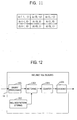
- the inclined tile is detected by using a different method from the inclined tile detecting method described in Embodiment 2.
- an inclined tile deciding unit 401 of Embodiment 5 is described with reference to Fig. 12.
- Fig. 12 shows a detailed configuration of the inclined tile deciding unit 401 of Embodiment 5.
- the reference numeral 1001 denotes a binary processing unit for binary processing the wavelet transformation coefficient being input.
- the reference numeral 1002 denotes an inclined pattern storing unit for storing the binary patterns of the pre-determined inclined direction.
- the reference numeral 1003 denotes a matching unit for collating the outputs of the binary processing unit 1001 and the inclined pattern storing unit 1002, and for identifying whether or not the focussed coefficient has the inclined directivity.
- the reference numeral 1004 denotes a counting unit for counting a number of times the coefficient has matched the binary pattern of the inclined direction.
- the reference numeral 1005 denotes a deciding unit for deciding whether or not a particular tile is the inclined tile based on the final number of coefficients of the inclined pattern.
- the binary processing unit 1001 processes the binary processing of each tile, by comparing, for example, the HH component Ct (x, y) having the resolution level n (the highest resolution) of the highest resolution and the threshold value Tc, as indicated below.
- a result of this binary proessing Bt (x, y) is matched to the binary patterns of the inclined direction which are stored beforehand the inclined pattern storing unit 1002. If it matches, 1 is output. If it does not match, then 0 is output.
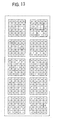
- Fig. 13 shows some of the examples of the binary patterns of the inclined direction which are stored beforehand in the inclined pattern storing unit 1002.
- the " x " in each binary pattern of the inclined direction shown in Fig. 13 displays a binary processing results which is not referred (Don't Care).
- the counting unit 1004 adds + 1 to the count value Nt, and if it isn't 1, the counting unit 1004 does not add at all. In this way, the numbers of coefficients Nt that are matched to the inclined pattern are counted for each tile.
- the deciding unit 1005 decides whether or not a particular tile is the inclined tile by comparing the final count value Nt and the threshold value Tn, as shown below.
- Embodiment 5 by binary processing the HH component of the resolution level n (the highest resolution) of the highest resolution in each tile, and by matching it with the binary pattern of the inclined direction ,which are registered in advance, it is possible to detect the inclined tile and demonstrate the effect that is similar to Embodiment 2.
- Embodiment 2 it is necessary to carry out the multiplication 25 times in order to calculate the auto-correlation coefficient, but according to the configuration which is explained in Embodiment 5, by storing the pre-determined inclined patterns, the inclined tile can be decided with just a processing of the pattern matching. In comparison to Embodiment 2, a smaller H / W scale is possible. At the same time, there is an effect that high-speed decision is possible.
- the inclined tile deciding unit 401 described in Embodiment 5, is configured to refer to the surrounding 24 pixels, as shown in Fig. 13.
- Embodiment 6 is characterized to refer to the surrounding 8 pixels and detect the inclined direction, as shown in Fig. 14
- the calculation of the degree of complexity of the complex tile deciding unit 111 has been described as the average power of the HH component, but it is not limited to this.
- the sub band to be referred is not limited to the HH component. All of the high frequency components of HL, LH and HH can be used.
- the degree of complexity can be calculated not with the average power, but with an absolute value of the coefficient or a variance of the coefficient, for instance. Especially, if the absolute value is used, there is no need to perform the square calculation such that the H / W scale can be small.
- the inclined tile deciding units 401 have been described to carry out calculations by referring to the HH component of the resolution level of the highest resolution. However, it is not limited to this. Other sub bands like HL, LL can be referred for the inclined tile detection.
- the inclined patterns which are shown in Figs. 13 and 14 described in Embodiments 5 and 6 are just some of the examples. It is not limited to this. Especially, in the same drawings, the inclined line (or the inclined edge) of 1 dot line width is illustrated, but it is allowable to detect those having line width of 2 dots, for example.
- the frequency weighting technology (the Frequency Weighting) is used, by multiplying the weight set to each sub band to the distortion.
- the image quality control which emphasizes the desired sub band by multiplying the weight set to each sub band to the wavelet transformation coefficient which is the output of the wavelet transforming unit 103.
- the distortion which is the output of the distortion memory 109 is directly input to the rate controlling unit 114 as it is, and the weight coefficient from the weight coefficient selecting unit 113 is input to the new multiplier which is installed between the wavelet transforming unit 103 and the quantizing unit 104 on the quantizing unit 104 side from the diverging point to the tile classifying unit 301. Because of this, for example, under the environment where the playback image is viewed from some distance away, since there is no need of the fine resolution, therefore, a lower weight is set to the highest resolution component of the wavelet transformation coefficient, and the amount of information can be effectively allocated to other low resolution transformation coefficients.
- the wavelet transforming unit 103 which is standardized in JPEG2000 and the like has been described as one example, however, according to the present invention, it is not limited to the wavelet transforming unit 103. Anything will do as long as it is the transforming system that can transform the image signal to the frequency component.
- the image coding device described in Embodiments 1 to 6 can be applied as LSI, and its image coding method described in Embodiments 1 to 6 can be applied as a software, to the image processing devices such as digital camera, security camera, and image scanner, which processes the static image as the input image.
- This image processing device can conduct various kinds of image processing of coded data where the code amount is controlled by the image coding device, and can conduct transmitting and receiving through a communication processing unit.
- each tile is classified into a plurality of categories according to its characteristic by referring to the transformation coefficient, the quantized distortion is weighted for each category, and the code amount of code data which is entropy coded is controlled based on the quantized distortion weighed with the weight coefficient. Therefore, in the case of coding the input image through the-tile division, the coding rate of the image signal is flexibly controlled for each tile.
Landscapes
- Engineering & Computer Science (AREA)
- Multimedia (AREA)
- Signal Processing (AREA)
- Theoretical Computer Science (AREA)
- Compression Or Coding Systems Of Tv Signals (AREA)
- Compression Of Band Width Or Redundancy In Fax (AREA)
- Compression, Expansion, Code Conversion, And Decoders (AREA)
Applications Claiming Priority (3)
| Application Number | Priority Date | Filing Date | Title |
|---|---|---|---|
| JP2002282402 | 2002-09-27 | ||
| JP2002282402A JP4045913B2 (ja) | 2002-09-27 | 2002-09-27 | 画像符号化装置、画像符号化方法、および画像処理装置 |
| PCT/JP2003/008901 WO2004030343A1 (ja) | 2002-09-27 | 2003-07-14 | 画像符号化装置、画像符号化方法、および画像処理装置 |
Publications (2)
| Publication Number | Publication Date |
|---|---|
| EP1545121A1 true EP1545121A1 (de) | 2005-06-22 |
| EP1545121A4 EP1545121A4 (de) | 2009-03-04 |
Family
ID=32040537
Family Applications (1)
| Application Number | Title | Priority Date | Filing Date |
|---|---|---|---|
| EP03741377A Withdrawn EP1545121A4 (de) | 2002-09-27 | 2003-07-14 | Bildcodierungseinrichtung, bildcodierungsverfahren und bildverarbeitungseinrichtung |
Country Status (7)
| Country | Link |
|---|---|
| US (1) | US7333661B2 (de) |
| EP (1) | EP1545121A4 (de) |
| JP (1) | JP4045913B2 (de) |
| KR (1) | KR100611705B1 (de) |
| CN (1) | CN1287584C (de) |
| TW (1) | TWI222327B (de) |
| WO (1) | WO2004030343A1 (de) |
Families Citing this family (24)
| Publication number | Priority date | Publication date | Assignee | Title |
|---|---|---|---|---|
| US7574063B2 (en) * | 2003-07-23 | 2009-08-11 | Canon Kabushiki Kaisha | Image coding method and apparatus |
| DE10354226B4 (de) * | 2003-11-20 | 2006-04-06 | Siemens Ag | Verfahren und Vorrichtung zum Laden eines in einem Archiv befindlichen Bildes mittels Pipeline Verarbeitung des in Chunks zerlegten Bildes mit Darstellung von Zwischenergebnissen in inkrementell erhöhter Auflösung |
| JP2005184511A (ja) | 2003-12-19 | 2005-07-07 | Nec Access Technica Ltd | デジタル画像符号化装置及びその方法並びにデジタル画像復号化装置及びその方法 |
| JP2006121645A (ja) * | 2004-09-24 | 2006-05-11 | Fuji Photo Film Co Ltd | 画像圧縮装置および画像圧縮プログラム |
| CN1917645B (zh) * | 2005-08-15 | 2012-12-19 | 华为技术有限公司 | 对系数块进行编码的方法 |
| JP2009531967A (ja) * | 2006-03-29 | 2009-09-03 | トムソン ライセンシング | マルチビュービデオ符号化方法および装置 |
| KR100809301B1 (ko) * | 2006-07-20 | 2008-03-04 | 삼성전자주식회사 | 엔트로피 부호화/복호화 방법 및 장치 |
| TWI323128B (en) | 2006-10-03 | 2010-04-01 | Quanta Comp Inc | Image processing apparatus and method |
| US8260068B2 (en) * | 2007-05-17 | 2012-09-04 | Sony Corporation | Encoding and decoding device and associated methodology for obtaining a decoded image with low delay |
| JP4569840B2 (ja) * | 2007-09-12 | 2010-10-27 | ソニー株式会社 | 画像符号化装置、画像符号化方法 |
| CN101335892B (zh) * | 2008-04-25 | 2010-06-09 | 太原科技大学 | 基于帧内模式决策的混合分布式视频编码方法 |
| US8218633B2 (en) * | 2008-06-18 | 2012-07-10 | Kiu Sha Management Limited Liability Company | Bidirectionally decodable Wyner-Ziv video coding |
| US8675210B2 (en) | 2009-03-13 | 2014-03-18 | Asml Netherlands B.V. | Level sensor, lithographic apparatus, and substrate surface positioning method |
| US8488107B2 (en) | 2009-03-13 | 2013-07-16 | Asml Netherlands B.V. | Lithographic apparatus and device manufacturing method involving a level sensor having multiple projection units and detection units |
| US8351024B2 (en) | 2009-03-13 | 2013-01-08 | Asml Netherlands B.V. | Lithographic apparatus and device manufacturing method involving a level sensor having a detection grating including three or more segments |
| JP5652658B2 (ja) * | 2010-04-13 | 2015-01-14 | ソニー株式会社 | 信号処理装置および方法、符号化装置および方法、復号装置および方法、並びにプログラム |
| JP5469127B2 (ja) * | 2011-05-30 | 2014-04-09 | 富士フイルム株式会社 | 画像データ符号化装置ならびにその動作制御方法およびそのプログラム |
| US20160140407A1 (en) * | 2013-06-17 | 2016-05-19 | Quantumrgb Ltd. | System and method for biometric identification |
| US10405002B2 (en) * | 2015-10-03 | 2019-09-03 | Tektronix, Inc. | Low complexity perceptual visual quality evaluation for JPEG2000 compressed streams |
| JP6857973B2 (ja) * | 2016-06-14 | 2021-04-14 | キヤノン株式会社 | 画像符号化装置及びその制御方法 |
| JP7001383B2 (ja) | 2017-07-28 | 2022-01-19 | キヤノン株式会社 | 符号化装置、符号化方法、及び、プログラム |
| US11423582B2 (en) * | 2019-03-01 | 2022-08-23 | Tencent America LLC | Method and apparatus for point cloud compression |
| CN113840145B (zh) * | 2021-09-23 | 2023-06-09 | 鹏城实验室 | 一种面向人眼观看和视觉分析联合优化的图像压缩方法 |
| CN118266210A (zh) * | 2021-12-29 | 2024-06-28 | 北京达佳互联信息技术有限公司 | 用于基于上下文的自适应二进制算术编码的概率计算的方法和设备 |
Family Cites Families (19)
| Publication number | Priority date | Publication date | Assignee | Title |
|---|---|---|---|---|
| USRE35781E (en) | 1989-01-31 | 1998-05-05 | Mitsubishi Denki Kabushiki Kaisha | Coding method of image information |
| JPH0834432B2 (ja) | 1989-01-31 | 1996-03-29 | 三菱電機株式会社 | 符号化装置及び符号化方法 |
| JPH02308672A (ja) | 1989-05-23 | 1990-12-21 | Fujitsu Ltd | カラー画像データ符号化方式 |
| JP2545302B2 (ja) * | 1989-12-25 | 1996-10-16 | 三菱電機株式会社 | 高能率符号化装置 |
| DE69032177T2 (de) | 1989-12-25 | 1998-11-12 | Mitsubishi Electric Corp | Kodierungsgerät |
| JPH0834434B2 (ja) | 1990-02-26 | 1996-03-29 | 三菱電機株式会社 | 符号化装置及び符号化方法 |
| JPH07154798A (ja) | 1993-05-31 | 1995-06-16 | Canon Inc | 画像符号化装置および画像符号化方法 |
| JP3115199B2 (ja) | 1994-12-16 | 2000-12-04 | 松下電器産業株式会社 | 画像圧縮符号化装置 |
| JP3213584B2 (ja) * | 1997-09-19 | 2001-10-02 | シャープ株式会社 | 画像符号化装置及び画像復号装置 |
| JP2001217718A (ja) | 2000-02-02 | 2001-08-10 | Canon Inc | 画像処理装置及び方法及び記憶媒体 |
| JP4254017B2 (ja) * | 2000-03-10 | 2009-04-15 | ソニー株式会社 | 画像符号化装置及び方法 |
| US6549674B1 (en) * | 2000-10-12 | 2003-04-15 | Picsurf, Inc. | Image compression based on tiled wavelet-like transform using edge and non-edge filters |
| US6668090B1 (en) | 2000-05-26 | 2003-12-23 | Eastman Kodak Company | Producing a compressed digital image organized into layers corresponding to increasing visual quality levels and providing rate-control of such compressed digital image |
| JP2002064719A (ja) * | 2000-08-17 | 2002-02-28 | Canon Inc | 画像処理装置およびその方法 |
| JP2002101311A (ja) | 2000-09-25 | 2002-04-05 | Jiro Adachi | 色毎に圧縮率を変える画像データ非可逆圧縮装置。 |
| JP3702778B2 (ja) * | 2000-11-27 | 2005-10-05 | ソニー株式会社 | 画像符号化装置及び方法 |
| US6895121B2 (en) * | 2001-07-03 | 2005-05-17 | Eastman Kodak Company | Method for utilizing subject content analysis for producing a compressed bit stream from a digital image |
| JP3615162B2 (ja) * | 2001-07-10 | 2005-01-26 | 日本電気株式会社 | 画像符号化方法及び画像符号化装置 |
| JP2003101794A (ja) * | 2001-09-25 | 2003-04-04 | Canon Inc | 画像符号化装置、及び画像符号化方法、並びにプログラム、記憶媒体 |
-
2002
- 2002-09-27 JP JP2002282402A patent/JP4045913B2/ja not_active Expired - Fee Related
-
2003
- 2003-06-27 TW TW92117535A patent/TWI222327B/zh not_active IP Right Cessation
- 2003-07-14 KR KR20047007959A patent/KR100611705B1/ko not_active Expired - Fee Related
- 2003-07-14 US US10/489,180 patent/US7333661B2/en not_active Expired - Lifetime
- 2003-07-14 CN CNB03801629XA patent/CN1287584C/zh not_active Expired - Fee Related
- 2003-07-14 WO PCT/JP2003/008901 patent/WO2004030343A1/ja not_active Ceased
- 2003-07-14 EP EP03741377A patent/EP1545121A4/de not_active Withdrawn
Also Published As
| Publication number | Publication date |
|---|---|
| TWI222327B (en) | 2004-10-11 |
| KR20040058323A (ko) | 2004-07-03 |
| TW200405730A (en) | 2004-04-01 |
| US20040240742A1 (en) | 2004-12-02 |
| KR100611705B1 (ko) | 2006-08-11 |
| WO2004030343A1 (ja) | 2004-04-08 |
| EP1545121A4 (de) | 2009-03-04 |
| CN1596536A (zh) | 2005-03-16 |
| JP2004120466A (ja) | 2004-04-15 |
| US7333661B2 (en) | 2008-02-19 |
| CN1287584C (zh) | 2006-11-29 |
| JP4045913B2 (ja) | 2008-02-13 |
Similar Documents
| Publication | Publication Date | Title |
|---|---|---|
| US7333661B2 (en) | Image coding device image coding method and image processing device | |
| Wu | An algorithmic study on lossless image compression | |
| US6157749A (en) | Image processing apparatus and method, and storing medium | |
| EP0827346B1 (de) | Verfahren und Vorrichtung zur Bildqualitätsvorhersage und -kontrolle | |
| EP0982949B1 (de) | Bildverarbeitungsverfahren und -vorrichtung | |
| EP0785669B1 (de) | Bildverarbeitungsverfahren und -vorrichtung | |
| US7916961B2 (en) | Compression encoder, compression encoding method and program | |
| EP0530022B1 (de) | Bildsignalkodierungsvorrichtung | |
| US6961462B2 (en) | Image processing method and image processor | |
| US8750638B2 (en) | Image processing apparatus, image processing method, and computer program | |
| US5454052A (en) | Method and apparatus for converting halftone images | |
| EP0584741A2 (de) | Vorrichtung zur Bildsignalkodierung | |
| US8351721B2 (en) | Image encoding device | |
| JPH0556282A (ja) | 画像符号化装置 | |
| EP0555095B1 (de) | Verfahren zur Komprimierung und Erweiterung eines Bildes durch Orthogonaltransformation und Kodierung des Bildes | |
| AU762996B2 (en) | An image compression system and method of determining quantisation parameters therefor | |
| KR100389893B1 (ko) | 영상 특성 분류법을 이용한 영상 부호화 장치 | |
| US7570821B2 (en) | Apparatus and method for image coding | |
| CN117097900A (zh) | 图像帧编码方法、装置、电子设备及计算机可读存储介质 | |
| JPH06350992A (ja) | データ圧縮回路 | |
| EP0544258B1 (de) | Bilddatenkompressionsmethode | |
| JP2002290763A (ja) | 画像処理方法及び画像処理装置 | |
| JP3489620B2 (ja) | 画質予測装置および画質制御装置 | |
| JP4424672B2 (ja) | 画像処理装置、画像処理方法、プログラム及び情報記録媒体 | |
| JPH08153199A (ja) | 画像処理装置 |
Legal Events
| Date | Code | Title | Description |
|---|---|---|---|
| PUAI | Public reference made under article 153(3) epc to a published international application that has entered the european phase |
Free format text: ORIGINAL CODE: 0009012 |
|
| 17P | Request for examination filed |
Effective date: 20040318 |
|
| AK | Designated contracting states |
Kind code of ref document: A1 Designated state(s): AT BE BG CH CY CZ DE DK EE ES FI FR GB GR HU IE IT LI LU MC NL PT RO SE SI SK TR |
|
| RBV | Designated contracting states (corrected) |
Designated state(s): DE FR GB |
|
| RAP1 | Party data changed (applicant data changed or rights of an application transferred) |
Owner name: MITSUBISHI DENKI KABUSHIKI KAISHA |
|
| A4 | Supplementary search report drawn up and despatched |
Effective date: 20090130 |
|
| RIC1 | Information provided on ipc code assigned before grant |
Ipc: H04N 1/41 20060101ALI20090126BHEP Ipc: H04N 7/26 20060101AFI20090126BHEP Ipc: H03M 7/30 20060101ALI20090126BHEP |
|
| 17Q | First examination report despatched |
Effective date: 20090507 |
|
| STAA | Information on the status of an ep patent application or granted ep patent |
Free format text: STATUS: THE APPLICATION HAS BEEN WITHDRAWN |
|
| 18W | Application withdrawn |
Effective date: 20181119 |