EP1544689B1 - Detent escapement for watches - Google Patents
Detent escapement for watches Download PDFInfo
- Publication number
- EP1544689B1 EP1544689B1 EP03028877A EP03028877A EP1544689B1 EP 1544689 B1 EP1544689 B1 EP 1544689B1 EP 03028877 A EP03028877 A EP 03028877A EP 03028877 A EP03028877 A EP 03028877A EP 1544689 B1 EP1544689 B1 EP 1544689B1
- Authority
- EP
- European Patent Office
- Prior art keywords
- finger
- locking
- tooth
- pallet
- wheel
- Prior art date
- Legal status (The legal status is an assumption and is not a legal conclusion. Google has not performed a legal analysis and makes no representation as to the accuracy of the status listed.)
- Expired - Lifetime
Links
- 230000000630 rising effect Effects 0.000 claims abstract description 4
- 239000004575 stone Substances 0.000 claims abstract 12
- 230000000903 blocking effect Effects 0.000 claims abstract 4
- 230000009194 climbing Effects 0.000 claims description 4
- 230000000694 effects Effects 0.000 description 6
- 230000010355 oscillation Effects 0.000 description 5
- 230000035939 shock Effects 0.000 description 5
- 230000008901 benefit Effects 0.000 description 4
- 210000003323 beak Anatomy 0.000 description 3
- 238000010420 art technique Methods 0.000 description 1
- 238000010276 construction Methods 0.000 description 1
- 238000000605 extraction Methods 0.000 description 1
- 238000005303 weighing Methods 0.000 description 1
Images


Classifications
-
- G—PHYSICS
- G04—HOROLOGY
- G04B—MECHANICALLY-DRIVEN CLOCKS OR WATCHES; MECHANICAL PARTS OF CLOCKS OR WATCHES IN GENERAL; TIME PIECES USING THE POSITION OF THE SUN, MOON OR STARS
- G04B15/00—Escapements
- G04B15/06—Free escapements
Definitions
- the present invention relates to a detent escapement for a timepiece comprising an escape wheel provided with teeth, a balance wheel on the axis of which are fixed a large plate equipped with a pulse pallet and a first actuating finger and a small plate on the circular periphery of which a notch is made, and a wedge-shaped blocker articulated on an axis, this blocker carrying a locking device of the escape wheel and a second actuating finger .
- a detent escapement broadly in line with the above description has already been proposed and described in the old Swiss patent CH-3299 due to Emile James.
- the proposed arrangement shows a trigger-rocker pivoted at one of its ends according to a conventional construction of this kind of exhaust.
- the axis of the balance carries a large plate, a first small plate carrying a notch and a second small plate carrying an actuating finger.
- the weighing lever has a locking device for the escape wheel - in this case a pallet of rest -, a pin, a spout and a leaf spring.
- the trigger-rocker is brought to rest by a spiral return spring. As the actuating finger lifts the trigger with the leaf spring, the nose enters the notch at the same time as the escape wheel advances one step. During the additional arc, the beak is clear of the notch and is near the circular periphery of the first small plateau.
- This arrangement has the advantage of preventing a tooth of the wheel from leaving the pallet rest when the timepiece receives a shock. At this time indeed, the spout is pressed briefly against the circular periphery of the first small plate, which stops the trigger-rocker which is immediately returned to rest by the spiral spring return.
- the detent escapement is suitable for large timepieces which make it possible to have large balance wheels with a large reserve of energy and a high torque for actuating the elastic member acting on the trigger. .
- the object of the present invention is to propose a timepiece of small dimensions, for example a wristwatch that is equipped with a detent escapement to replace, for example, the classic anchor escapement and to benefit from the advantages conferred by this escapement relaxation.
- a timepiece of small dimensions for example a wristwatch that is equipped with a detent escapement to replace, for example, the classic anchor escapement and to benefit from the advantages conferred by this escapement relaxation.
- the expansion escapement of the present invention is remarkable in that there is no elastic member acting on the trigger.
- the detent escapement of the invention in addition to meeting the definition of the first paragraph of this description, is characterized in that the first and second actuating fingers are shaped in such a way that when the large and small trays rotate in a first direction, the first finger causes the second finger which bypasses a first side said first finger to disengage the locking device of the escape wheel, the second finger being then driven by a rising edge which is provided with the notch of the small plate to reengage the locking device in the escape wheel, and such that when the large and small trays rotate in a second direction, opposite the first direction, the first finger causes the second finger which bypasses a second side, opposite the first, of said first finger to maintain the engagement of the locking device in the escape wheel.
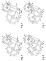
- the Figures 1 to 3 illustrate the escapement relaxation object of the present invention according to a first embodiment.
- the exhaust comprises an escape wheel 2 provided with teeth 3. Without being shown in the drawings, the escape wheel is driven by the wheel of the timepiece which receives its driving force from a cylinder.
- On the axis 16 of the balance (not shown) is fixed a large plate 4 which is equipped with a pulse pallet 5 and a first actuating finger 14.
- On the same axis 16 is fixed a small plate 23 with a circular periphery 24 and a notch 22.
- the figures also show that the exhaust comprises a blocker 6 in the form of rocker hinged on an axis 8.
- the blocker 6 carries a locking device or a pallet 7 and a second finger actuator 11.
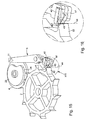
- first and second actuating fingers 14 and 11 are shaped such that, when the large and small trays 4 and 23 rotate in a second direction b, opposite to the first, the first finger 14 drives the second finger 11 bypassing a second side 21 , opposite the first, of said first finger 14, which has the effect of maintaining the engagement of the pallet rest 7 in the escape wheel 2.
- tooth 62 has come into contact with the rest pallet 7.
- the tip of the tooth 62 pushed by the kinetic energy of the wheel 2, is housed on a rest line 33 of which the pallet 7 is provided.
- the face 30 (see also figures 1 and 2 ) against which abuts a tooth of the wheel 2 comprises a first rest plane 31 located at the front of the pallet 7 and a second rest plane 32 located at the rear, this second plane being inclined relative to the first for
- the point of the tooth 62 by pulling effect is housed on the line of rest 33 and stops there, the second rest plane 32 standing in front of it. preventing him from continuing his journey. It will be observed that this device allows to do without stop pin that is generally available to limit the frog of the blocker.
- the different phases of operation remain the same as those exposed and illustrated in Figures 4 to 13 .
- the tip of the tooth 62 by pulling effect is housed on the line of rest 44 and stops there, the second rest plane 43 standing in front of it, preventing it from continuing on its way.
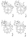
- the Figures 17 to 19 illustrate the detent escapement according to a third embodiment.
- the single pallet of the first embodiment has been replaced by first and second pallets 50 and 51 cooperating respectively with first and second teeth 62 and 63 of the escape wheel 2.
- the first and second pallets rest respectively have first and second rest planes 52 and 53 inclined relative to each other.
- the locking device is interposed between the teeth of the escape wheel, it is the first rest plane 52 of the first pallet 50 which intercepts the first tooth 62 of the wheel 2.
- This wheel is then blocked while done when the second rest plane 53 of the second pallet 51 comes into contact with the second tooth 63 of the wheel 2, the inclination of the rest plane 52 being chosen such that the climbing of the tooth 63 along said plan 52 is not possible.
- the second tooth 63 climbs the second rest plane 53 of the second blade 51 forcing the wheel 2 to move back slightly against the driving force that exercise on it.
- the second tooth 63 finally returns to the first point of contact of the second rest plane 53 with the second tooth 63, when the second finger 11 leaves the first finger 14.
Landscapes
- Physics & Mathematics (AREA)
- General Physics & Mathematics (AREA)
- Micromachines (AREA)
- Electric Clocks (AREA)
- Thermotherapy And Cooling Therapy Devices (AREA)
- Finger-Pressure Massage (AREA)
- Feeding And Watering For Cattle Raising And Animal Husbandry (AREA)
- Portable Nailing Machines And Staplers (AREA)
- Inorganic Insulating Materials (AREA)
- Compounds Of Unknown Constitution (AREA)
Abstract
Description
La présente invention est relative à un échappement à détente pour pièce d'horlogerie comprenant une roue d'échappement munie de dents, un balancier sur l'axe duquel sont fixés un grand plateau équipé d'une palette d'impulsion et d'un premier doigt d'actionnement et un petit plateau sur le pourtour circulaire duquel est pratiquée une entaille, et un bloqueur en forme de bascule articulée sur un axe, ce bloqueur portant un dispositif de blocage de la roue d'échappement et un second doigt d'actionnement.The present invention relates to a detent escapement for a timepiece comprising an escape wheel provided with teeth, a balance wheel on the axis of which are fixed a large plate equipped with a pulse pallet and a first actuating finger and a small plate on the circular periphery of which a notch is made, and a wedge-shaped blocker articulated on an axis, this blocker carrying a locking device of the escape wheel and a second actuating finger .
Un échappement à détente répondant dans les grandes lignes à la description ci-dessus a déjà été proposé et décrit dans l'ancien brevet suisse
Cette disposition a l'avantage d'empêcher qu'une dent de la roue ne quitte la palette de repos lorsque la pièce d'horlogerie reçoit un choc. A ce moment en effet, le bec vient appuyer un court instant contre le pourtour circulaire du premier petit plateau, ce qui arrête la détente-bascule qui est tout de suite ramenée au repos par le ressort spiral de rappel.This arrangement has the advantage of preventing a tooth of the wheel from leaving the pallet rest when the timepiece receives a shock. At this time indeed, the spout is pressed briefly against the circular periphery of the first small plate, which stops the trigger-rocker which is immediately returned to rest by the spiral spring return.
Ce qui vient d'être dit met le doigt sur une faiblesse affectant l'échappement à détente, à savoir celle d'être sensible aux chocs, aussi cet échappement est-il réservé surtout aux chronomètres de grande dimension ou aux chronomètres de marine peu sollicités mécaniquement, cet échappement ayant la réputation de ne pas bien convenir aux montres-bracelets.What has just been said points to a weakness affecting the detent escapement, namely that of being sensitive to shocks, so this escapement is reserved especially for large chronometers or marine chronometers little solicited mechanically, this exhaust has the reputation of not being well suited to wristwatches.
Dans ce que propose le brevet suisse cité, on remarque cependant que l'extraction du bec hors de l'entaille n'est possible que grâce au ressort spiral qui exerce un effort de rappel sur la détente-bascule. En effet, l'entaille porte des flancs abrupts, quasi radiaux empêchant toute sortie du bec qui serait provoquée par la seule rotation du plateau lui-même.In the proposed Swiss patent cited, however, it is noted that the extraction of the beak out of the notch is possible only through the spiral spring which exerts a return force on the trigger-rocker. Indeed, the notch has abrupt, almost radial flanks preventing any exit of the beak that would be caused by the only rotation of the plate itself.
Un autre échappement à détente répondant partiellement à la description du premier paragraphe de ce texte a été proposé par Breguet et fait l'objet d'une illustration (figure 402) parue dans l'ouvrage de George Daniels intitulé l'Art de Breguet (Londres 1975). Il s'agit d'un échappement de chronomètre à détente pivotée faisant appel à un bloqueur en forme de bascule pivotée sur un axe. Une branche de la bascule est équipée d'une palette de repos coopérant avec les dents de la roue d'échappement. L'autre branche coopère avec un dispositif à ressort monté sur le plateau solidaire du balancier. Ce dispositif à ressort est une lame très courte susceptible à la fois d'actionner la bascule quand le plateau tourne dans un sens et de rester sans effet sur ladite bascule lorsque le plateau tourne dans le sens opposé. On trouve donc là le principe de tout échappement à détente dans lequel l'impulsion au balancier n'est donnée qu'une fois pas oscillation pendant laquelle la roue d'échappement progresse d'un pas angulaire tandis que, dans l'échappement à ancre, ladite roue avance d'un demi-pas à chaque alternance. On mesure ici un des avantages apporté par l'échappement à détente puisque l'énergie perdue par suite de l'inertie de la roue d'échappement n'intervient qu'une fois par oscillation au lieu d'une fois par alternance.Another escapement with a relaxation partially corresponding to the description of the first paragraph of this text was proposed by Breguet and is the object of an illustration (figure 402) published in the book of George Daniels entitled the Art of Breguet (London 1975). It is a revolving stopwatch escapement using a rocker blocker pivoted on an axle. A branch of the rocker is equipped with a pallet of rest cooperating with the teeth of the escape wheel. The other branch cooperates with a spring device mounted on the plate secured to the balance. This spring device is a very short blade capable both to actuate the latch when the plate rotates in one direction and to remain without effect on said latch when the plate rotates in the opposite direction. We thus find there the principle of any escapement with expansion in which the impulse to the balance is given only once oscillation during which the escape wheel progresses of an angular step while, in the escapement with anchor said wheel advances by half a step at each alternation. Here, one of the advantages of the detent escapement is measured since the energy lost as a result of the inertia of the escape wheel only occurs once per oscillation instead of once alternately.
On a dit plus haut que l'échappement à détente convient à des pièces d'horlogerie de grande dimension qui permettent de disposer de balanciers importants présentant une grande réserve d'énergie et un fort couple pour actionner l'organe élastique qui agit sur la détente. Lors d'une alternance en effet, il faut tendre l'organe élastique pour dégager la palette de repos, alors qu'à l'alternance suivante il faut détendre le même organe élastique pour l'amener à contourner la détente qui n'est alors pas actionnée.It has been said above that the detent escapement is suitable for large timepieces which make it possible to have large balance wheels with a large reserve of energy and a high torque for actuating the elastic member acting on the trigger. . During an alternation indeed, it is necessary to stretch the elastic member to release the pallet rest, while the following alternation it is necessary to relax the same elastic member to cause it to bypass the trigger which is then not operated.
Le but de la présente invention est de proposer une pièce d'horlogerie de petites dimensions, par exemple une montre-bracelet qui soit équipée d'un échappement à détente pour remplacer, par exemple, l'échappement à ancre classique et pour bénéficier des avantages conférés par cet échappement à détente. On comprendra cependant qu'utiliser les techniques antérieures connues et décrites ci-dessus conduirait à un échec puisque l'énergie développée par le balancier d'une montre-bracelet est bien inférieure à celle développée par une montre-chronomètre, ce balancier se montrant donc incapable de vaincre les forces agissant sur la détente.The object of the present invention is to propose a timepiece of small dimensions, for example a wristwatch that is equipped with a detent escapement to replace, for example, the classic anchor escapement and to benefit from the advantages conferred by this escapement relaxation. However, it will be understood that using the prior art techniques known and described above would lead to a failure since the energy developed by the pendulum of a wristwatch is much lower than that developed by a chronometer-watch, this pendulum thus showing itself unable to defeat the forces acting on the trigger.
Ainsi l'échappement à détente de la présente invention est-il remarquable en ce qu'il se passe d'organe élastique agissant sur la détente. Dans ce but, l'échappement à détente de l'invention, en plus qu'il répond à la définition du premier paragraphe de cette description, est caractérisé en ce que les premier et second doigts d'actionnement sont conformés de telle façon que lorsque les grand et petit plateaux tournent dans un premier sens, le premier doigt entraîne le second doigt lequel contourne un premier côté dudit premier doigt pour dégager le dispositif de blocage de la roue d'échappement, le second doigt étant entraîné ensuite par un flanc montant dont est pourvue l'entaille du petit plateau pour réengager le dispositif de blocage dans la roue d'échappement, et de telle façon que lorsque les grand et petit plateaux tournent dans un second sens, opposé au premier sens, le premier doigt entraîne le second doigt lequel contourne un second côté, opposé au premier, dudit premier doigt pour maintenir l'engagement du dispositif de blocage dans la roue d'échappement.Thus, the expansion escapement of the present invention is remarkable in that there is no elastic member acting on the trigger. For this purpose, the detent escapement of the invention, in addition to meeting the definition of the first paragraph of this description, is characterized in that the first and second actuating fingers are shaped in such a way that when the large and small trays rotate in a first direction, the first finger causes the second finger which bypasses a first side said first finger to disengage the locking device of the escape wheel, the second finger being then driven by a rising edge which is provided with the notch of the small plate to reengage the locking device in the escape wheel, and such that when the large and small trays rotate in a second direction, opposite the first direction, the first finger causes the second finger which bypasses a second side, opposite the first, of said first finger to maintain the engagement of the locking device in the escape wheel.
L'invention va être expliquée maintenant en détail ci-dessous par plusieurs modes d'exécution donnés à titre d'exemple, ces exécutions étant illustrées par les dessins annexés dans lesquels :
- la
figure 1 est une vue en plan d'un premier mode d'exécution de l'échappement selon l'invention, - la
figure 2 est une vue en perspective de l'échappement montré enfigure 1 , - la
figure 3 est un agrandissement de la zone III de lafigure 2 , - les
figures 4 à 13 sont des vues en plan explicitant plusieurs phases de fonctionnement de l'échappement selon l'invention, - la
figure 14 est une vue en plan d'un deuxième mode d'exécution selon l'invention, - la
figure 15 est une vue en perspective de l'échappement montré enfigure 14 , - la
figure 16 est un agrandissement de la zone XVI de lafigure 15 , - la
figure 17 est une vue en plan d'un troisième mode d'exécution de l'invention, - la
figure 18 est une vue en perspective de l'échappement montré enfigure 17 , et - la
figure 19 est un agrandissement de la zone XIX de lafigure 18 .
- the
figure 1 is a plan view of a first embodiment of the escapement according to the invention, - the
figure 2 is a perspective view of the exhaust shown infigure 1 , - the
figure 3 is an enlargement of zone III of thefigure 2 , - the
Figures 4 to 13 are plan views explaining several operating phases of the escapement according to the invention, - the
figure 14 is a plan view of a second embodiment according to the invention, - the
figure 15 is a perspective view of the exhaust shown infigure 14 , - the
figure 16 is an enlargement of the XVI zone of thefigure 15 , - the
figure 17 is a plan view of a third embodiment of the invention, - the
figure 18 is a perspective view of the exhaust shown infigure 17 , and - the
figure 19 is an enlargement of the XIX zone of thefigure 18 .
Les
Comme il a été dit plus haut, l'échappement à détente de la présente invention est remarquable en ce qu'il se passe d'organe élastique agissant sur le bloqueur ou détente 6. Pour parvenir à ce résultat, les
Comme on l'a rappelé plus haut, on retrouve bien là le principe de l'échappement à détente dans lequel l'impulsion au balancier n'est donnée qu'une fois par oscillation. On vient de voir en effet que la roue d'échappement est libérée lorsque les plateaux tournent dans un sens alors qu'elle reste bloquée lorsque ces plateaux tournent dans l'autre sens.As we recalled above, we find here the principle of the escapement trigger in which the impulse to the balance is given only once per oscillation. It has just been seen that the escape wheel is released when the trays rotate in one direction while it remains blocked when these trays turn in the other direction.
On va décrire maintenant en détail le fonctionnement de l'échappement à détente réalisé selon l'invention en s'aidant des
En
En
En
En
En
En
En
En
La
En
En
Les
Pour le reste, les différentes phases de fonctionnement restent les mêmes que celles exposées et illustrées en
Les
Pour le reste, les différentes phases de fonctionnement restent les mêmes que celles expliquées à propos des
Pour que le système décrit fonctionne correctement, il est indispensable que les premier et second doigts d'actionnement 14 et 11 soient conformés de façon à glisser aisément l'un sur l'autre puisque, on l'a vu, le doigt 14 entraîne le doigt 11 en parcourant un tour complet autour de ce dernier. Plusieurs formes peuvent être envisagées pour parvenir à ce but. Les figures illustrant cette description montrent que le premier doigt d'actionnement 14 présente une section parallélépipédique et que le second doigt d'actionnement présente une section triangulaire dont les angles sont arrondis. L'invention n'est bien sûr pas limitée à ces formes, par exemple ce peut très bien être le premier doigt 14 qui présente une section triangulaire avec angles arrondis alors que le second doigt 11 montre une section parallélépipédique.For the described system to function properly, it is essential for the first and
L'échappement décrit ci-dessus paraît entièrement nouveau en ce sens qu'il fonctionne sans l'aide d'aucun organe élastique et qu'en ce sens il est économe en énergie consommée au balancier. En ce sens également, il convient parfaitement à équiper de petites pièces d'horlogerie, par exemple une montre-bracelet pourvue naturellement d'un balancier de petite taille livrant peu d'énergie. En fait, l'échappement décrit peut-il s'appeler échappement à détente alors qu'une détente présuppose un organe élastique pour l'actionner ? De l'échappement à détente subsiste encore, dans la présente invention, l'action directe de la roue d'échappement sur le balancier ainsi que l'impulsion unique conférée au balancier pour une oscillation de ce dernier.The exhaust described above seems entirely new in the sense that it operates without the help of any elastic member and that in this sense it is energy efficient consumed balance. In this sense also, it is ideal for equipping small timepieces, for example a wristwatch naturally provided with a small beam delivering little energy. In fact, can the escapement described be called detent escapement while a relaxation presupposes an elastic member to actuate it? The detent escapement still remains, in the present invention, the direct action of the escape wheel on the balance and the single pulse imparted to the balance for an oscillation of the latter.
On remarquera encore en terminant que tout l'échappement décrit n'est pas plus encombrant qu'un échappement à ancre monté sur une montre-bracelet, sinon moins, alors que les échappements à détente connus prennent beaucoup de place, raison pour laquelle on limite leur emploi aux montres de grandes dimensions.Finally, we will notice that all the exhaust described is not more bulky than an anchor escapement mounted on a wristwatch, if not less, while the known detent escapements take up a lot of space, which is why we limit their use in large watches.
Claims (7)
- Detent escapement for a timepiece including an escapement wheel (2) fitted with teeth (3), a balance, on the pin (16) of which are fixed a large roller (4) fitted with an impulse pallet-stone (5) and a first actuating finger (14) and a small roller (23) on the circular periphery (24) of which there is made a notch (22), and a blocking member in the form of a lever (6) hinged on a pin (8), said blocking member carrying a locking device (7; 40, 41; 50, 51) of the escapement wheel (2) and a second actuating finger (11), characterised in that said first and second fingers are shaped such that when the large and small rollers (4 and 23) rotate in a first direction (a), the first finger (14) drives the second finger (11) which moves around a first side (20) of said first finger (14) to release the device locking the escapement wheel (2), the second finger (11) being then driven by a rising flank (25) of the notch (22) of the small roller (23) to re-engage the locking device in the escapement wheel (2), and such that when the large and small rollers (4 and 23) rotate in a second direction (b) opposite to the first, the first finger (14) drives the second finger (11) which moves around a second side (21), opposite to the first side, of said first finger (14) to keep the locking device engaged in the escapement wheel (2).
- Escapement according to claim 1, characterised in that the locking device is a locking pallet-stone (7) including a face (30) against which a tooth (62) of the escapement wheel (2) abuts, said face (30) including a first locking face (31) located in the front position of the pallet-stone (7) and a second locking face (32) located in the rear position, the second face being inclined with respect to the first to form a locking line (33) on which the tooth (62) of the wheel (2) rests, the first locking face (31) intercepting the tooth (62) of the wheel (2) when the pallet-stone (7) is inserted between two teeth (60 and 62), said tooth (62) climbing over said second locking face (32) when the first finger (14) drives by its second side (21) the second finger (11) said tooth (62) finally returning to the locking line (33) when the second finger (11) leaves the first finger (14).
- Escapement according to claim 1, characterised in that locking device includes first (40) and second (41) locking pallet-stones arranged one above each other and respectively having first (42) and second (43) locking faces inclined in relation to each other to form a locking line (44) on which the tooth (62) of the wheel (2) rests, the first locking face (42) intercepting the tooth (62) of the wheel (2) when the first pallet-stone (40) is inserted between two teeth (60 and 62), said tooth (62) climbing over the second face (43) of the second pallet-stone (41) when the first finger (14) drives the second finger (11), via its second side (21), said tooth (62) finally returning to the locking line (44) when the second finger (11) leaves the first finger (14).
- Escapement according to claim 1, characterised in that the locking device includes first (50) and second (51) locking faces respectively cooperating with first (62) and second (63) teeth of the escapement wheel (2), said first and second locking pallet-stones respectively having first (52) and second (53) locking faces inclined in relation to each other, the first locking face (52) of the first pallet-stone (50) intercepting the first tooth (62) of the wheel (2) when the locking device is inserted between the teeth of said wheel, the latter being locked when the second locking face (53) of the second pallet-stone (51) enters into contact with the second tooth (63), said second tooth (63) climbing over said second locking face (53) of said second pallet (51) when said first finger (14) drives said second finger (11) via its second sides (21) said second finger (63) finally returning to the point of contact of the second locking face (53) with the second tooth (63) when the second finger (11) leaves the first finger (14).
- Escapement according to any of claims 2 to 4, characterised in that the blocking member (6) is arranged such that the second finger (11) is immobilised in proximity to, but without touching, the circular periphery (24) of the small roller (23), when the locking device locks the escapement wheel (2).
- Escapement according to claim 1, characterised in that the first actuating finger (14) has a parallelepiped cross section and in that the second actuating finger (11) has a triangular cross section whose angles are rounded.
- Escapement according to claim 1, characterised in that the first actuating finger (14) has a triangular cross section whose angles are rounded and in that the second actuating finger (11) has a parallelepiped cross section.
Priority Applications (8)
| Application Number | Priority Date | Filing Date | Title |
|---|---|---|---|
| EP03028877A EP1544689B1 (en) | 2003-12-16 | 2003-12-16 | Detent escapement for watches |
| DE60331447T DE60331447D1 (en) | 2003-12-16 | 2003-12-16 | Chronometer escapement for watches |
| AT03028877T ATE459026T1 (en) | 2003-12-16 | 2003-12-16 | CHRONOMETER ESCAPEMENT FOR WATCHES |
| US11/000,379 US7192180B2 (en) | 2003-12-16 | 2004-12-01 | Detent escapement for timepiece |
| SG200407838A SG113030A1 (en) | 2003-12-16 | 2004-12-07 | Detent escapement for timepiece |
| CNB2004101012214A CN100549873C (en) | 2003-12-16 | 2004-12-15 | The escapement of clock and watch |
| JP2004362958A JP4444809B2 (en) | 2003-12-16 | 2004-12-15 | Watch detent escapement |
| HK05106308.9A HK1073893B (en) | 2003-12-16 | 2005-07-25 | Detent escapement for timepiece |
Applications Claiming Priority (1)
| Application Number | Priority Date | Filing Date | Title |
|---|---|---|---|
| EP03028877A EP1544689B1 (en) | 2003-12-16 | 2003-12-16 | Detent escapement for watches |
Publications (2)
| Publication Number | Publication Date |
|---|---|
| EP1544689A1 EP1544689A1 (en) | 2005-06-22 |
| EP1544689B1 true EP1544689B1 (en) | 2010-02-24 |
Family
ID=34486216
Family Applications (1)
| Application Number | Title | Priority Date | Filing Date |
|---|---|---|---|
| EP03028877A Expired - Lifetime EP1544689B1 (en) | 2003-12-16 | 2003-12-16 | Detent escapement for watches |
Country Status (7)
| Country | Link |
|---|---|
| US (1) | US7192180B2 (en) |
| EP (1) | EP1544689B1 (en) |
| JP (1) | JP4444809B2 (en) |
| CN (1) | CN100549873C (en) |
| AT (1) | ATE459026T1 (en) |
| DE (1) | DE60331447D1 (en) |
| SG (1) | SG113030A1 (en) |
Families Citing this family (25)
| Publication number | Priority date | Publication date | Assignee | Title |
|---|---|---|---|---|
| ATE390653T1 (en) | 2005-03-30 | 2008-04-15 | Montres Breguet Sa | CHRONOMETER ESCAPEMENT FOR WATCHES |
| ATE390652T1 (en) * | 2005-03-30 | 2008-04-15 | Montres Breguet Sa | CHRONOMETER ESCAPEMENT FOR WATCHES |
| EP1770452A1 (en) * | 2005-09-30 | 2007-04-04 | Peter Baumberger | Detent escapement for timepieces |
| ATE447731T1 (en) * | 2007-04-18 | 2009-11-15 | Eta Sa Mft Horlogere Suisse | ANCHOR ESCAPEMENT COMPRISING TWO ESCUPATION GEARS |
| DE602007003445D1 (en) * | 2007-04-18 | 2010-01-07 | Eta Sa Mft Horlogere Suisse | Inhibition, which includes two escapement wheels |
| DE602007004446D1 (en) * | 2007-04-18 | 2010-03-11 | Eta Sa Mft Horlogere Suisse | Direct impulse inhibition for watches |
| DE602007004447D1 (en) * | 2007-04-18 | 2010-03-11 | Eta Sa Mft Horlogere Suisse | Anchor escapement for watches |
| JP5366319B2 (en) | 2009-09-14 | 2013-12-11 | セイコーインスツル株式会社 | Detent escapement and mechanical watch having the same |
| JP5441168B2 (en) * | 2010-03-10 | 2014-03-12 | セイコーインスツル株式会社 | Detent escapement and mechanical watch |
| EP2407830B1 (en) * | 2010-07-15 | 2014-11-05 | Rolex Sa | Timepiece |
| JP5729666B2 (en) | 2010-09-14 | 2015-06-03 | セイコーインスツル株式会社 | Watch detent escapement and mechanical watch |
| JP5729665B2 (en) * | 2010-09-14 | 2015-06-03 | セイコーインスツル株式会社 | Watch detent escapement and mechanical watch |
| EP2450755B1 (en) | 2010-11-04 | 2015-01-21 | Nivarox-FAR S.A. | Synchronous escapement for clockwork |
| JP5740766B2 (en) * | 2011-03-09 | 2015-07-01 | セイコーインスツル株式会社 | Watch detent escapement and mechanical watch |
| JP5794613B2 (en) * | 2011-03-11 | 2015-10-14 | セイコーインスツル株式会社 | Watch detent escapement and mechanical watch |
| CN106462105B (en) * | 2014-01-13 | 2019-05-17 | 洛桑联邦理工学院 | Mechanical isotropic harmonic oscillator, system including the same and timing device |
| CN107250925B (en) * | 2014-01-13 | 2020-06-23 | 洛桑联邦理工学院 | Mechanical isotropic harmonic oscillator and oscillator system |
| EP2947522B1 (en) * | 2014-05-20 | 2017-05-03 | Société anonyme de la Manufacture d'Horlogerie Audemars Piguet & Cie | Timepiece pallet for mechanical oscillator and timer-controlled timepiece trigger mechanism |
| US9538975B2 (en) * | 2015-04-08 | 2017-01-10 | Toshiba Medical Systems Corporation | Scatter correction method and apparatus for computed tomography imaging |
| EP3121660B1 (en) * | 2015-07-21 | 2018-02-14 | Cartier International AG | Detent escapement mechanism and timepiece comprising such a mechanism |
| US12265359B2 (en) | 2016-07-06 | 2025-04-01 | Ecole Polytechnique Federale De Lausanne (Epfl) | General 2 degree of freedom isotropic harmonic oscillator and associated time base without escapement or with simplified escapement |
| EP3273308B1 (en) * | 2016-07-18 | 2019-06-12 | Sowind S.A. | Exhaust mechanism |
| EP3336613B1 (en) * | 2016-12-16 | 2020-03-11 | Association Suisse pour la Recherche Horlogère | Timepiece resonator with two balances arranged to oscillate in a single plane |
| JP6901876B2 (en) * | 2017-03-13 | 2021-07-14 | セイコーインスツル株式会社 | Escapement, watch movements and watches |
| JP7428556B2 (en) * | 2020-03-16 | 2024-02-06 | セイコーウオッチ株式会社 | Watch parts, movements and watches |
Family Cites Families (10)
| Publication number | Priority date | Publication date | Assignee | Title |
|---|---|---|---|---|
| CH64175A (en) | 1913-05-20 | 1914-03-16 | Bernhard Pitzing | shovel |
| US3538705A (en) * | 1968-11-07 | 1970-11-10 | Hamilton Watch Co | Escapement |
| CH578754B5 (en) * | 1972-10-12 | 1976-08-13 | Favre Marc & Co Sa | |
| CH599585B5 (en) * | 1975-08-05 | 1978-05-31 | Ebauchesfabrik Eta Ag | |
| US3975962A (en) * | 1975-08-13 | 1976-08-24 | Les Fabriques D'assortiments Reunies | Click work for a watch movement |
| EP0018796B1 (en) * | 1979-04-30 | 1984-11-07 | George Daniels | Watches, clocks and chronometers and escapements therefor |
| CN1040698C (en) * | 1994-07-26 | 1998-11-11 | 矫大羽 | rotary escapement governor |
| EP1221637B1 (en) * | 2001-01-09 | 2008-03-12 | Ulysse Nardin S.A. | Escapement for timekeeper |
| DE60334916D1 (en) * | 2003-12-04 | 2010-12-23 | Montres Breguet Sa | Chronometer escapement for watches |
| EP1538490B1 (en) * | 2003-12-04 | 2007-05-30 | Montres Breguet S.A. | Detent escapement for wrist-watches |
-
2003
- 2003-12-16 EP EP03028877A patent/EP1544689B1/en not_active Expired - Lifetime
- 2003-12-16 AT AT03028877T patent/ATE459026T1/en not_active IP Right Cessation
- 2003-12-16 DE DE60331447T patent/DE60331447D1/en not_active Expired - Lifetime
-
2004
- 2004-12-01 US US11/000,379 patent/US7192180B2/en not_active Expired - Lifetime
- 2004-12-07 SG SG200407838A patent/SG113030A1/en unknown
- 2004-12-15 CN CNB2004101012214A patent/CN100549873C/en not_active Expired - Lifetime
- 2004-12-15 JP JP2004362958A patent/JP4444809B2/en not_active Expired - Lifetime
Also Published As
| Publication number | Publication date |
|---|---|
| JP2005181318A (en) | 2005-07-07 |
| JP4444809B2 (en) | 2010-03-31 |
| US20050128880A1 (en) | 2005-06-16 |
| DE60331447D1 (en) | 2010-04-08 |
| CN100549873C (en) | 2009-10-14 |
| US7192180B2 (en) | 2007-03-20 |
| EP1544689A1 (en) | 2005-06-22 |
| CN1629751A (en) | 2005-06-22 |
| ATE459026T1 (en) | 2010-03-15 |
| HK1073893A1 (en) | 2005-10-21 |
| SG113030A1 (en) | 2005-07-28 |
Similar Documents
| Publication | Publication Date | Title |
|---|---|---|
| EP1544689B1 (en) | Detent escapement for watches | |
| EP1538491B1 (en) | Detent escapement for watches | |
| EP1708046B1 (en) | Detent escapement for timepieces | |
| EP1983388B1 (en) | Direct-pulse escapement for timepiece | |
| EP2453322B1 (en) | Fast time quantity indicator corrector for a timepiece | |
| EP1983389B1 (en) | Escapement comprising two escape wheels | |
| EP1041459B1 (en) | Escapement for timepiece | |
| EP1967919B1 (en) | Exhaust with tangential impulses | |
| EP1538490B1 (en) | Detent escapement for wrist-watches | |
| EP1983391B1 (en) | Lever escapement for timepiece | |
| WO2008145539A1 (en) | Lever escapement for timepiece | |
| EP1983390B1 (en) | Lever escapement comprising two escape wheels | |
| CH702930A2 (en) | Exhaust watch to protection against shocks. | |
| EP1708047B1 (en) | Detent escapement for timepieces | |
| EP4198641B1 (en) | Natural escapement for timepiece movement and timepiece movement comprising such an escapement | |
| EP3818417B1 (en) | Timepiece escapement mechanism | |
| EP1122617B1 (en) | Locking device for timepiece | |
| EP3510449B1 (en) | Escapement mechanism | |
| CH696944A5 (en) | Detent escapement for e.g. wristwatch, has finger driven by flank to re-engage locking device, and another finger to drive former finger surrounding side of latter finger to maintain engagement of device in escape wheel when rollers turn | |
| EP3584641B1 (en) | Automatically starting and secured detent escapement for timepieces | |
| EP1276021B1 (en) | Escape for timekeeper | |
| EP3475765B1 (en) | Clock escapement | |
| CH712288A1 (en) | Bi-functional sting, locking and securing device for timepiece, and watch exhaust. | |
| EP3982203A1 (en) | Timepiece escapement with semi-direct pulse | |
| CH696942A5 (en) | Detent escapement for e.g. wrist watch, has escape wheel provided with teeth, plate integrated to balance, and elastic member i.e. balance spring, having large length including coils coiled around center and assembled on plate |
Legal Events
| Date | Code | Title | Description |
|---|---|---|---|
| PUAI | Public reference made under article 153(3) epc to a published international application that has entered the european phase |
Free format text: ORIGINAL CODE: 0009012 |
|
| AK | Designated contracting states |
Kind code of ref document: A1 Designated state(s): AT BE BG CH CY CZ DE DK EE ES FI FR GB GR HU IE IT LI LU MC NL PT RO SE SI SK TR |
|
| AX | Request for extension of the european patent |
Extension state: AL LT LV MK |
|
| 17P | Request for examination filed |
Effective date: 20051222 |
|
| AKX | Designation fees paid |
Designated state(s): AT BE BG CH CY CZ DE DK EE ES FI FR GB GR HU IE IT LI LU MC NL PT RO SE SI SK TR |
|
| GRAP | Despatch of communication of intention to grant a patent |
Free format text: ORIGINAL CODE: EPIDOSNIGR1 |
|
| GRAS | Grant fee paid |
Free format text: ORIGINAL CODE: EPIDOSNIGR3 |
|
| GRAA | (expected) grant |
Free format text: ORIGINAL CODE: 0009210 |
|
| AK | Designated contracting states |
Kind code of ref document: B1 Designated state(s): AT BE BG CH CY CZ DE DK EE ES FI FR GB GR HU IE IT LI LU MC NL PT RO SE SI SK TR |
|
| REG | Reference to a national code |
Ref country code: GB Ref legal event code: FG4D Free format text: NOT ENGLISH |
|
| REG | Reference to a national code |
Ref country code: CH Ref legal event code: EP Ref country code: CH Ref legal event code: NV Representative=s name: ICB INGENIEURS CONSEILS EN BREVETS SA |
|
| REG | Reference to a national code |
Ref country code: IE Ref legal event code: FG4D Free format text: LANGUAGE OF EP DOCUMENT: FRENCH |
|
| REF | Corresponds to: |
Ref document number: 60331447 Country of ref document: DE Date of ref document: 20100408 Kind code of ref document: P |
|
| REG | Reference to a national code |
Ref country code: NL Ref legal event code: VDEP Effective date: 20100224 |
|
| PG25 | Lapsed in a contracting state [announced via postgrant information from national office to epo] |
Ref country code: PT Free format text: LAPSE BECAUSE OF FAILURE TO SUBMIT A TRANSLATION OF THE DESCRIPTION OR TO PAY THE FEE WITHIN THE PRESCRIBED TIME-LIMIT Effective date: 20100625 |
|
| PG25 | Lapsed in a contracting state [announced via postgrant information from national office to epo] |
Ref country code: SI Free format text: LAPSE BECAUSE OF FAILURE TO SUBMIT A TRANSLATION OF THE DESCRIPTION OR TO PAY THE FEE WITHIN THE PRESCRIBED TIME-LIMIT Effective date: 20100224 Ref country code: FI Free format text: LAPSE BECAUSE OF FAILURE TO SUBMIT A TRANSLATION OF THE DESCRIPTION OR TO PAY THE FEE WITHIN THE PRESCRIBED TIME-LIMIT Effective date: 20100224 Ref country code: AT Free format text: LAPSE BECAUSE OF FAILURE TO SUBMIT A TRANSLATION OF THE DESCRIPTION OR TO PAY THE FEE WITHIN THE PRESCRIBED TIME-LIMIT Effective date: 20100224 |
|
| REG | Reference to a national code |
Ref country code: IE Ref legal event code: FD4D |
|
| PG25 | Lapsed in a contracting state [announced via postgrant information from national office to epo] |
Ref country code: SE Free format text: LAPSE BECAUSE OF FAILURE TO SUBMIT A TRANSLATION OF THE DESCRIPTION OR TO PAY THE FEE WITHIN THE PRESCRIBED TIME-LIMIT Effective date: 20100224 Ref country code: IE Free format text: LAPSE BECAUSE OF FAILURE TO SUBMIT A TRANSLATION OF THE DESCRIPTION OR TO PAY THE FEE WITHIN THE PRESCRIBED TIME-LIMIT Effective date: 20100224 Ref country code: GR Free format text: LAPSE BECAUSE OF FAILURE TO SUBMIT A TRANSLATION OF THE DESCRIPTION OR TO PAY THE FEE WITHIN THE PRESCRIBED TIME-LIMIT Effective date: 20100525 Ref country code: ES Free format text: LAPSE BECAUSE OF FAILURE TO SUBMIT A TRANSLATION OF THE DESCRIPTION OR TO PAY THE FEE WITHIN THE PRESCRIBED TIME-LIMIT Effective date: 20100604 Ref country code: CY Free format text: LAPSE BECAUSE OF FAILURE TO SUBMIT A TRANSLATION OF THE DESCRIPTION OR TO PAY THE FEE WITHIN THE PRESCRIBED TIME-LIMIT Effective date: 20100224 Ref country code: EE Free format text: LAPSE BECAUSE OF FAILURE TO SUBMIT A TRANSLATION OF THE DESCRIPTION OR TO PAY THE FEE WITHIN THE PRESCRIBED TIME-LIMIT Effective date: 20100224 Ref country code: NL Free format text: LAPSE BECAUSE OF FAILURE TO SUBMIT A TRANSLATION OF THE DESCRIPTION OR TO PAY THE FEE WITHIN THE PRESCRIBED TIME-LIMIT Effective date: 20100224 Ref country code: RO Free format text: LAPSE BECAUSE OF FAILURE TO SUBMIT A TRANSLATION OF THE DESCRIPTION OR TO PAY THE FEE WITHIN THE PRESCRIBED TIME-LIMIT Effective date: 20100224 |
|
| PG25 | Lapsed in a contracting state [announced via postgrant information from national office to epo] |
Ref country code: CZ Free format text: LAPSE BECAUSE OF FAILURE TO SUBMIT A TRANSLATION OF THE DESCRIPTION OR TO PAY THE FEE WITHIN THE PRESCRIBED TIME-LIMIT Effective date: 20100224 Ref country code: SK Free format text: LAPSE BECAUSE OF FAILURE TO SUBMIT A TRANSLATION OF THE DESCRIPTION OR TO PAY THE FEE WITHIN THE PRESCRIBED TIME-LIMIT Effective date: 20100224 Ref country code: BG Free format text: LAPSE BECAUSE OF FAILURE TO SUBMIT A TRANSLATION OF THE DESCRIPTION OR TO PAY THE FEE WITHIN THE PRESCRIBED TIME-LIMIT Effective date: 20100524 |
|
| PLBE | No opposition filed within time limit |
Free format text: ORIGINAL CODE: 0009261 |
|
| STAA | Information on the status of an ep patent application or granted ep patent |
Free format text: STATUS: NO OPPOSITION FILED WITHIN TIME LIMIT |
|
| PG25 | Lapsed in a contracting state [announced via postgrant information from national office to epo] |
Ref country code: DK Free format text: LAPSE BECAUSE OF FAILURE TO SUBMIT A TRANSLATION OF THE DESCRIPTION OR TO PAY THE FEE WITHIN THE PRESCRIBED TIME-LIMIT Effective date: 20100224 |
|
| 26N | No opposition filed |
Effective date: 20101125 |
|
| PG25 | Lapsed in a contracting state [announced via postgrant information from national office to epo] |
Ref country code: IT Free format text: LAPSE BECAUSE OF FAILURE TO SUBMIT A TRANSLATION OF THE DESCRIPTION OR TO PAY THE FEE WITHIN THE PRESCRIBED TIME-LIMIT Effective date: 20100224 |
|
| BERE | Be: lapsed |
Owner name: MONTRES BREGUET S.A. Effective date: 20101231 |
|
| PG25 | Lapsed in a contracting state [announced via postgrant information from national office to epo] |
Ref country code: MC Free format text: LAPSE BECAUSE OF NON-PAYMENT OF DUE FEES Effective date: 20101231 |
|
| PG25 | Lapsed in a contracting state [announced via postgrant information from national office to epo] |
Ref country code: BE Free format text: LAPSE BECAUSE OF NON-PAYMENT OF DUE FEES Effective date: 20101231 |
|
| PG25 | Lapsed in a contracting state [announced via postgrant information from national office to epo] |
Ref country code: HU Free format text: LAPSE BECAUSE OF FAILURE TO SUBMIT A TRANSLATION OF THE DESCRIPTION OR TO PAY THE FEE WITHIN THE PRESCRIBED TIME-LIMIT Effective date: 20100825 Ref country code: LU Free format text: LAPSE BECAUSE OF NON-PAYMENT OF DUE FEES Effective date: 20101216 |
|
| PG25 | Lapsed in a contracting state [announced via postgrant information from national office to epo] |
Ref country code: TR Free format text: LAPSE BECAUSE OF FAILURE TO SUBMIT A TRANSLATION OF THE DESCRIPTION OR TO PAY THE FEE WITHIN THE PRESCRIBED TIME-LIMIT Effective date: 20100224 |
|
| REG | Reference to a national code |
Ref country code: FR Ref legal event code: PLFP Year of fee payment: 13 |
|
| REG | Reference to a national code |
Ref country code: FR Ref legal event code: PLFP Year of fee payment: 14 |
|
| REG | Reference to a national code |
Ref country code: FR Ref legal event code: PLFP Year of fee payment: 15 |
|
| PGFP | Annual fee paid to national office [announced via postgrant information from national office to epo] |
Ref country code: GB Payment date: 20221116 Year of fee payment: 20 Ref country code: FR Payment date: 20221123 Year of fee payment: 20 Ref country code: DE Payment date: 20220616 Year of fee payment: 20 |
|
| PGFP | Annual fee paid to national office [announced via postgrant information from national office to epo] |
Ref country code: CH Payment date: 20230101 Year of fee payment: 20 |
|
| P01 | Opt-out of the competence of the unified patent court (upc) registered |
Effective date: 20230611 |
|
| REG | Reference to a national code |
Ref country code: DE Ref legal event code: R071 Ref document number: 60331447 Country of ref document: DE |
|
| REG | Reference to a national code |
Ref country code: CH Ref legal event code: PL |
|
| REG | Reference to a national code |
Ref country code: GB Ref legal event code: PE20 Expiry date: 20231215 |
|
| PG25 | Lapsed in a contracting state [announced via postgrant information from national office to epo] |
Ref country code: GB Free format text: LAPSE BECAUSE OF EXPIRATION OF PROTECTION Effective date: 20231215 |
|
| PG25 | Lapsed in a contracting state [announced via postgrant information from national office to epo] |
Ref country code: GB Free format text: LAPSE BECAUSE OF EXPIRATION OF PROTECTION Effective date: 20231215 |