EP1544394A2 - Vorrichtung zum Feststellen eines Flügels, insbesondere einer Tür oder eines Fensters - Google Patents
Vorrichtung zum Feststellen eines Flügels, insbesondere einer Tür oder eines Fensters Download PDFInfo
- Publication number
- EP1544394A2 EP1544394A2 EP04028656A EP04028656A EP1544394A2 EP 1544394 A2 EP1544394 A2 EP 1544394A2 EP 04028656 A EP04028656 A EP 04028656A EP 04028656 A EP04028656 A EP 04028656A EP 1544394 A2 EP1544394 A2 EP 1544394A2
- Authority
- EP
- European Patent Office
- Prior art keywords
- lever
- overload
- door
- spring
- slider
- Prior art date
- Legal status (The legal status is an assumption and is not a legal conclusion. Google has not performed a legal analysis and makes no representation as to the accuracy of the status listed.)
- Granted
Links
Images
Classifications
-
- E—FIXED CONSTRUCTIONS
- E05—LOCKS; KEYS; WINDOW OR DOOR FITTINGS; SAFES
- E05F—DEVICES FOR MOVING WINGS INTO OPEN OR CLOSED POSITION; CHECKS FOR WINGS; WING FITTINGS NOT OTHERWISE PROVIDED FOR, CONCERNED WITH THE FUNCTIONING OF THE WING
- E05F3/00—Closers or openers with braking devices, e.g. checks; Construction of pneumatic or liquid braking devices
- E05F3/22—Additional arrangements for closers, e.g. for holding the wing in opened or other position
- E05F3/221—Mechanical power-locks, e.g. for holding the wing open or for free-moving zones
- E05F3/222—Mechanical power-locks, e.g. for holding the wing open or for free-moving zones electrically operated
-
- E—FIXED CONSTRUCTIONS
- E05—LOCKS; KEYS; WINDOW OR DOOR FITTINGS; SAFES
- E05F—DEVICES FOR MOVING WINGS INTO OPEN OR CLOSED POSITION; CHECKS FOR WINGS; WING FITTINGS NOT OTHERWISE PROVIDED FOR, CONCERNED WITH THE FUNCTIONING OF THE WING
- E05F1/00—Closers or openers for wings, not otherwise provided for in this subclass
- E05F1/002—Closers or openers for wings, not otherwise provided for in this subclass controlled by automatically acting means
- E05F1/006—Closers or openers for wings, not otherwise provided for in this subclass controlled by automatically acting means by emergency conditions, e.g. fire
-
- E—FIXED CONSTRUCTIONS
- E05—LOCKS; KEYS; WINDOW OR DOOR FITTINGS; SAFES
- E05F—DEVICES FOR MOVING WINGS INTO OPEN OR CLOSED POSITION; CHECKS FOR WINGS; WING FITTINGS NOT OTHERWISE PROVIDED FOR, CONCERNED WITH THE FUNCTIONING OF THE WING
- E05F5/00—Braking devices, e.g. checks; Stops; Buffers
- E05F5/12—Braking devices, e.g. checks; Stops; Buffers specially for preventing the closing of a wing before another wing has been closed
-
- E—FIXED CONSTRUCTIONS
- E05—LOCKS; KEYS; WINDOW OR DOOR FITTINGS; SAFES
- E05F—DEVICES FOR MOVING WINGS INTO OPEN OR CLOSED POSITION; CHECKS FOR WINGS; WING FITTINGS NOT OTHERWISE PROVIDED FOR, CONCERNED WITH THE FUNCTIONING OF THE WING
- E05F3/00—Closers or openers with braking devices, e.g. checks; Construction of pneumatic or liquid braking devices
- E05F3/22—Additional arrangements for closers, e.g. for holding the wing in opened or other position
- E05F2003/228—Arrangements where the end of the closer arm is sliding in a track
-
- E—FIXED CONSTRUCTIONS
- E05—LOCKS; KEYS; WINDOW OR DOOR FITTINGS; SAFES
- E05Y—INDEXING SCHEME ASSOCIATED WITH SUBCLASSES E05D AND E05F, RELATING TO CONSTRUCTION ELEMENTS, ELECTRIC CONTROL, POWER SUPPLY, POWER SIGNAL OR TRANSMISSION, USER INTERFACES, MOUNTING OR COUPLING, DETAILS, ACCESSORIES, AUXILIARY OPERATIONS NOT OTHERWISE PROVIDED FOR, APPLICATION THEREOF
- E05Y2201/00—Constructional elements; Accessories therefor
- E05Y2201/20—Brakes; Disengaging means; Holders; Stops; Valves; Accessories therefor
- E05Y2201/218—Holders
- E05Y2201/22—Locks
-
- E—FIXED CONSTRUCTIONS
- E05—LOCKS; KEYS; WINDOW OR DOOR FITTINGS; SAFES
- E05Y—INDEXING SCHEME ASSOCIATED WITH SUBCLASSES E05D AND E05F, RELATING TO CONSTRUCTION ELEMENTS, ELECTRIC CONTROL, POWER SUPPLY, POWER SIGNAL OR TRANSMISSION, USER INTERFACES, MOUNTING OR COUPLING, DETAILS, ACCESSORIES, AUXILIARY OPERATIONS NOT OTHERWISE PROVIDED FOR, APPLICATION THEREOF
- E05Y2201/00—Constructional elements; Accessories therefor
- E05Y2201/40—Motors; Magnets; Springs; Weights; Accessories therefor
- E05Y2201/404—Function thereof
- E05Y2201/41—Function thereof for closing
-
- E—FIXED CONSTRUCTIONS
- E05—LOCKS; KEYS; WINDOW OR DOOR FITTINGS; SAFES
- E05Y—INDEXING SCHEME ASSOCIATED WITH SUBCLASSES E05D AND E05F, RELATING TO CONSTRUCTION ELEMENTS, ELECTRIC CONTROL, POWER SUPPLY, POWER SIGNAL OR TRANSMISSION, USER INTERFACES, MOUNTING OR COUPLING, DETAILS, ACCESSORIES, AUXILIARY OPERATIONS NOT OTHERWISE PROVIDED FOR, APPLICATION THEREOF
- E05Y2900/00—Application of doors, windows, wings or fittings thereof
- E05Y2900/10—Application of doors, windows, wings or fittings thereof for buildings or parts thereof
- E05Y2900/13—Type of wing
- E05Y2900/132—Doors
Definitions
- the invention relates to a device for detecting a wing, in particular a door or a window according to the preamble of claim 1.
- U1 is a locking device for one with a door closer provided door, with a arranged between the door leaf and frame Sliding arm, which at its end at the wing or the frame joint stored and arranged at its other end in a frame or on the door Guide rail is slidably guided with a slider.
- an electrically lockable holding device with a movable Latch, which under the action of a spring in the path of movement of the sliding arm is urged, as well as with a movable bearing on which the spring is supported is, and with an electromagnet, whose sliding anchor plate with cooperates with the movable bearing.
- the movable bearing is a cross to the Sliding pivotal recording, about its pivot axis in the recording recorded with a sliding edge cooperating with the slider limited from the recording outstanding catch in both directions against the pressure of the spring supported in the receptacle in the same Direction is pivotable.
- the recording works on a parallel to Slideway arranged and the electromagnet penetrating bolt with arranged transversely to the slide, parallel to the sliding track slidable anchor plate together.
- the locking device can not be used for different holding forces be because the spring force is not adjustable. Maybe the arrangement can jam the locking lug in the receiving housing.
- From DE 38 06 662 C2 is a locking device for one with a door closer provided door, with a arranged between the door and the frame Sliding arm, with a slider, in one on the frame or on the door arranged guide rail is slidably guided and with an electromagnet interacts.
- the locking device has a movable stop element on, which with the electromagnet on one in the guide rail is mounted permanently mountable first carriage. That as a stop lever trained movable stop member projects under the action of a spring in the Guideway of the slider into it, wherein the stop lever with a second Carriage cooperates, which slidably mounted in the first carriage is, and a cooperating with the electromagnet anchor plate carries.
- This arrangement is complicated by a variety of components.
- the invention has the object of providing a locking device, which works safely.
- Electromagnetic locking devices are often used with Door operators provided to keep door leaves of fire doors open. Thereby Hallways can be freely committed, in case of fire, the locking device can be automatically lifted, causing the door leaves through the door drives getting closed. Often these are two-leaved, with a closing sequence control provided doors, whereby the inactive leaf before the with an overlap, the Fold, provided active leaf closes.
- the vane-side glider is activated a triggering device which cooperates with a locking device which acting on the aisle side door closer. This will make the closing of the active leaf prevented when the inactive leaf in an at least partially is open position.
- the inventive device is for small to very large holding forces, which depending on the door leaf sizes and weights are suitable. It is simple and easy to adjust. By the overload protection the door system is prevented from being damaged by operating the door leaves protected locking device, and the door wings can through Pass over the locking device to be closed manually.
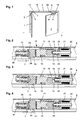
- Fig. 1 is a two-leaf door with a moving leaf 1 and a stationary leaf 2, with one above the door 1, 2 in or on the door frame arranged slide 9, in which the on the slide arms 5, 6 of the door drives 3, 4 arranged slider 7, 8 are guided. Furthermore, the closing sequence regulation a triggering device 10, a locking device 11 and for keeping open the door 1, 2, the locking devices 12, which with the sliders 7, 8 cooperate, arranged within the slide rail 9.
- the locking device 12 is identical for both doors 1, 2.
- FIG. 2 shows the basic position, in which projects a stop element 14 in the movement path of the slider 7, 8.
- the locking device 12 can be activated to keep the door leaf 1, 2 open be.
- the locking device 12 has a receptacle 13, which in the slide rail 9 to determine the desired hold-open position of the door 1, 2 moved and with a clamping element, not shown, for example a Clamping screw, can be specified.
- a clamping element not shown, for example a Clamping screw
- the rod 19 has the other end a blocking element 15, which acts on an elastic element, the return spring 22 is, whereby the armature plate 20 is applied to the electromagnet 21 becomes.
- the blocking element 15 is guided in the receptacle 13, wherein these in the area the guide through a material insert or a coating for improved Sliding properties can be formed.
- a Rotary axis 18 pivotable lever 17 is arranged at the receptacle 13 .
- For the rotation axis 18 are provided a plurality of positions, whereby the locking device 12 for various Door weights are adjusted to different locking forces can.
- the lever 17 has a recess 16 which cooperates with the blocking element 15.
- the recess 16 may also have a coating or formed as a material used to improve sliding properties be.
- the electromagnet 21 pivots the acted upon by the door drive 3, 4 slider 7, 8, the lever 17th on the slope on the stop element 14 in the release position, as shown in the Fig. 3 is shown.
- pivoting the lever 17 is the by switching off the electromagnet 21 slidable locking element 15 from the recess 16 urged against the spring 22.
- the slider 7, 8, the stopper element 14 underrun, after which the lever 17 by the locking member 15, which is inserted by the spring 22 in the recess 16, in the normal position pivots back as shown in FIG.
- the anchor plate 20 comes into abutment with the electromagnet 21, and the locking device can by energizing the electromagnet to be activated.
- the locking device 12 has an overload protection, which by pivoting the door 1, 2 can be triggered. This will damage on the door wings 1, 2 and the door operators 3, 4 avoided, and it is also a deliberate driving over the locking device 12, bypassing the electrical Triggering possible.
- Fig. 4 shows the overload release, wherein the electromagnet 21 is energized and the lever 17 through the blocking element 15 on Pivoting is prevented.
- the stop element 14 acts with a by an elastic Element, such as an overload spring 25, overload element overloaded 23 together, which in a recess 24 of the stop element 14 engages.
- the bias of the overload spring 25 can be adjusted by an adjusting screw 26 are adjusted.
- the overload protection triggers by an increased force of the slider 7, 8 on the stop element 14, wherein the overload element 23 from the recess 24 is urged and the stop element 14 on the slider 7, the eighth pushes. If the slider 7, 8 from the area below the stop element 14th moved away, so the overload element 23 engages by the overload spring 25 in the recess 24, whereby the stop member 14 in the locked position returns.
Landscapes
- Engineering & Computer Science (AREA)
- Mechanical Engineering (AREA)
- Business, Economics & Management (AREA)
- Emergency Management (AREA)
- Power-Operated Mechanisms For Wings (AREA)
Abstract
Description
- Fig. 1
- eine zweiflügelige, mit Türschließern und einer Schließfolgeregelung versehene Tür, mit in einer Gleitschiene angeordneten Feststellvorrichtungen zum Offenhalten der Türflügel;
- Fig. 2
- eine Ansicht einer der Feststellvorrichtungen gemäß Fig. 1 in geschnittener Darstellung, wobei sich die Feststellvorrichtung in der den Flügel offenhaltenden Stellung befindet;
- Fig. 3
- eine Ansicht gemäß Fig. 2, wobei sich die Feststellvorrichtung in Freigabestellung befindet;
- Fig. 4
- eine Ansicht gemäß Fig. 2, wobei die Feststellvorrichtung durch Überlast überfahren wird.
- 1
- Gangflügel
- 2
- Standflügel
- 3
- gangflügelseitiger Türantrieb
- 4
- standflügelseitiger Türantrieb
- 5
- Gleitarm gangflügelseitiger Türantrieb
- 6
- Gleitarm standflügelseitiger Türantrieb
- 7
- gangflügelseitiger Gleiter
- 8
- standflügelseitiger Gleiter
- 9
- Gleitschiene
- 10
- Auslösevorrichtung
- 11
- Sperrvorrichtung
- 12
- Feststellvorrichtung
- 13
- Aufnahme
- 14
- Anschlagelement
- 15
- Sperrelement
- 16
- Aussparung
- 17
- Hebel
- 18
- Drehachse
- 19
- Stange
- 20
- Ankerplatte
- 21
- Elektromagnet
- 22
- Rückholfeder
- 23
- Überlastelement
- 24
- Aussparung
- 25
- Überlastfeder
- 26
- Einstellschraube
Claims (8)
- Vorrichtung zum Feststellen eines Flügels, insbesondere einer Tür oder eines Fensters, mit einem Antrieb, wobei der Antrieb einen Gleitarm aufweist, an welchem ein in einer Gleitschiene geführter Gleiter angeordnet ist, der durch einen in oder an der Führungsschiene vorgesehenen, an einem schwenkbaren Hebel angeordneten, bewegbaren federbeaufschlagten Anschlagelement in der Gleitschiene in seiner Bewegung blockiert werden kann, wobei der schwenkbare Hebel mit einem Elektromagneten zusammenwirkt, indem ein Sperrelement kraftschlüssig mit dem Hebel verbindbar ist,
dadurch gekennzeichnet, dass dem Hebel (17) eine Überlastsicherung (23, 25, 26) zugeordnet ist, wobei eine Überlastfeder (25) auf ein Überlastelement (23) wirkt, welches kraftschlüssig mit dem Anschlagelement (14) verbindbar ist, wobei die Federkraft der Überlastfeder (25) in der Gleitschiene (9) zugänglich einstellbar ist. - Vorrichtung nach Anspruch 1,
dadurch gekennzeichnet, dass die Auslösekraft der Überlastsicherung (23, 24, 25, 26) durch eine Einstellschraube (26) einstellbar ist. - Vorrichtung nach Anspruch 1,
dadurch gekennzeichnet, dass das Überlastelement (23) im Kraftschlussbereich kegelförmig ausgebildet ist. - Vorrichtung nach Anspruch 1,
dadurch gekennzeichnet, dass das Anschlagelement (14) durch den Gleiter (7, 8) annähernd senkrecht zur Bewegungsbahn des Gleiters (7, 8) verschiebbar ist. - Vorrichtung nach Anspruch 1,
dadurch gekennzeichnet, dass das Anschlagelement (14) der Feststellvorrichtung (12) vom Gleiter (7, 8) vollständig überfahrbar ist. - Vorrichtung nach Anspruch 1,
dadurch gekennzeichnet, dass die Drehachse (18) des Hebels (17) in ihrer Lage zur Auswahl unterschiedlicher Feststellkräfte verändert werden kann. - Vorrichtung nach Anspruch 1,
dadurch gekennzeichnet, dass das Sperrelement (15) bei der Beaufschlagung durch den Elektromagneten (21) den Hebel (17) in seine den Türflügel (1 bzw. 2) feststellende Stellung verschwenkt. - Vorrichtung nach Anspruch 1,
dadurch gekennzeichnet, dass das Sperrelement (15) durch ein elastisches Element (22) in Richtung auf die den Hebel (17) blockierende Stellung beaufschlagt ist.
Applications Claiming Priority (2)
| Application Number | Priority Date | Filing Date | Title |
|---|---|---|---|
| DE10359979A DE10359979B4 (de) | 2003-12-18 | 2003-12-18 | Vorrichtung zum Feststellen eines Flügels, insbesondere einer Tür oder eines Fensters |
| DE10359979 | 2003-12-18 |
Publications (3)
| Publication Number | Publication Date |
|---|---|
| EP1544394A2 true EP1544394A2 (de) | 2005-06-22 |
| EP1544394A3 EP1544394A3 (de) | 2010-01-13 |
| EP1544394B1 EP1544394B1 (de) | 2012-02-01 |
Family
ID=34485525
Family Applications (1)
| Application Number | Title | Priority Date | Filing Date |
|---|---|---|---|
| EP04028656A Expired - Lifetime EP1544394B1 (de) | 2003-12-18 | 2004-12-03 | Vorrichtung zum Feststellen eines Flügels, insbesondere einer Tür oder eines Fensters |
Country Status (3)
| Country | Link |
|---|---|
| EP (1) | EP1544394B1 (de) |
| AT (1) | ATE543976T1 (de) |
| DE (1) | DE10359979B4 (de) |
Cited By (7)
| Publication number | Priority date | Publication date | Assignee | Title |
|---|---|---|---|---|
| CN102437522A (zh) * | 2011-04-27 | 2012-05-02 | 上海市电力公司 | 用于防止柜门误关闭的专用小门挡栓 |
| EP2434078A3 (de) * | 2010-09-23 | 2015-11-18 | Assa Abloy Sicherheitstechnik GmbH | Arretiereinheit zum Feststellen einer Tür in einer Haltestellung, Türschließsystem mit einer solchen Arretiereinheit und Verfahren zum Betrieb einer solchen Arretiereinheit |
| EP2735681A3 (de) * | 2012-11-26 | 2017-09-13 | GEZE GmbH | Antrieb für einen Flügel einer Tür oder eines Fensters |
| CN109098579A (zh) * | 2018-09-29 | 2018-12-28 | 苏州市富尔达科技股份有限公司 | 一种防火窗用闭窗器 |
| EP3489445A1 (de) | 2017-11-22 | 2019-05-29 | dormakaba Deutschland GmbH | Verriegelungsvorrichtung, insbesondere offenhaltevorrichtung, für eine türbetätigeranordnung |
| US20220090422A1 (en) * | 2020-09-21 | 2022-03-24 | Abloy Oy | Hold-open arrester arrangement having a hold-open function to hold a door open |
| EP4520908A1 (de) * | 2023-09-08 | 2025-03-12 | GEZE GmbH | Schliessersystem sowie zweiflügelige tür |
Families Citing this family (6)
| Publication number | Priority date | Publication date | Assignee | Title |
|---|---|---|---|---|
| DE102005001315B4 (de) * | 2005-01-11 | 2007-05-24 | Dorma Gmbh + Co. Kg | Elektromechanische Feststellvorrichtung für einen Türantrieb |
| DE102005040659B4 (de) * | 2005-08-26 | 2008-07-24 | Dorma Gmbh + Co. Kg | Elektromechanische Feststellvorrichtung für Türflügel |
| DE102008022715A1 (de) | 2008-05-07 | 2009-11-12 | Dorma Gmbh + Co. Kg | Feststellvorrichtung für eine Tür |
| DE102008056214B4 (de) * | 2008-11-06 | 2014-09-25 | Assa Abloy Sicherheitstechnik Gmbh | Arretiereinheit für einen Türschließer, Türschließsystem, Verwendung einer Arretiereinheit und Verfahren zum Arretieren einer Tür |
| DE102014211549B4 (de) | 2014-06-17 | 2018-06-14 | Geze Gmbh | Feststellvorrichtung für einen Flügel |
| DE102015210949B3 (de) * | 2015-06-15 | 2016-10-06 | Geze Gmbh | Feststellvorrichtung für einen Flügel |
Family Cites Families (7)
| Publication number | Priority date | Publication date | Assignee | Title |
|---|---|---|---|---|
| US4656690A (en) * | 1984-10-18 | 1987-04-14 | Ryobi Limited | Fireproof door closer and holder having a solenoid and a toggle mechanism |
| DE3806662C2 (de) * | 1987-03-05 | 1999-06-10 | Geze Grundstueck Beteiligung | Feststellvorrichtung für eine mit einem Türschließer versehene Tür |
| DE3916216A1 (de) * | 1989-05-18 | 1990-11-22 | Geze Gmbh & Co | Feststellvorrichtung fuer eine tuer, wobei die haltekraft einstellbar ist |
| DE9303973U1 (de) * | 1993-03-18 | 1994-07-14 | Gretsch-Unitas GmbH, 71254 Ditzingen | Türschließer |
| DE9306539U1 (de) * | 1993-04-30 | 1993-07-08 | Eco Schulte GmbH & Co KG, 5750 Menden | Feststellvorrichtung für eine mit einem Türschließer versehene Tür |
| DE29623040U1 (de) * | 1996-02-21 | 1997-09-18 | Dorma Gmbh + Co. Kg, 58256 Ennepetal | Elektromechanische Feststellvorrichtung für Türflügel mit einem Türschließer |
| US6499185B1 (en) * | 2000-10-30 | 2002-12-31 | Dorma Door Controls, Inc | Apparatus for holding a door open |
-
2003
- 2003-12-18 DE DE10359979A patent/DE10359979B4/de not_active Withdrawn - After Issue
-
2004
- 2004-12-03 EP EP04028656A patent/EP1544394B1/de not_active Expired - Lifetime
- 2004-12-03 AT AT04028656T patent/ATE543976T1/de active
Cited By (10)
| Publication number | Priority date | Publication date | Assignee | Title |
|---|---|---|---|---|
| EP2434078A3 (de) * | 2010-09-23 | 2015-11-18 | Assa Abloy Sicherheitstechnik GmbH | Arretiereinheit zum Feststellen einer Tür in einer Haltestellung, Türschließsystem mit einer solchen Arretiereinheit und Verfahren zum Betrieb einer solchen Arretiereinheit |
| CN102437522A (zh) * | 2011-04-27 | 2012-05-02 | 上海市电力公司 | 用于防止柜门误关闭的专用小门挡栓 |
| CN102437522B (zh) * | 2011-04-27 | 2014-11-12 | 上海市电力公司 | 用于防止柜门误关闭的专用小门挡栓 |
| EP2735681A3 (de) * | 2012-11-26 | 2017-09-13 | GEZE GmbH | Antrieb für einen Flügel einer Tür oder eines Fensters |
| EP3489445A1 (de) | 2017-11-22 | 2019-05-29 | dormakaba Deutschland GmbH | Verriegelungsvorrichtung, insbesondere offenhaltevorrichtung, für eine türbetätigeranordnung |
| CN109098579A (zh) * | 2018-09-29 | 2018-12-28 | 苏州市富尔达科技股份有限公司 | 一种防火窗用闭窗器 |
| CN109098579B (zh) * | 2018-09-29 | 2024-02-20 | 苏州市富尔达科技股份有限公司 | 一种防火窗用闭窗器 |
| US20220090422A1 (en) * | 2020-09-21 | 2022-03-24 | Abloy Oy | Hold-open arrester arrangement having a hold-open function to hold a door open |
| US11619087B2 (en) * | 2020-09-21 | 2023-04-04 | Abloy Oy | Hold-open arrester arrangement having a hold-open function to hold a door open |
| EP4520908A1 (de) * | 2023-09-08 | 2025-03-12 | GEZE GmbH | Schliessersystem sowie zweiflügelige tür |
Also Published As
| Publication number | Publication date |
|---|---|
| DE10359979B4 (de) | 2008-10-16 |
| DE10359979A1 (de) | 2005-07-28 |
| EP1544394A3 (de) | 2010-01-13 |
| ATE543976T1 (de) | 2012-02-15 |
| EP1544394B1 (de) | 2012-02-01 |
Similar Documents
| Publication | Publication Date | Title |
|---|---|---|
| EP0726379A1 (de) | Schliessfolgeregler für eine zweiflügelige Tür | |
| DE102008048994B4 (de) | Feststellvorrichtung für einen Flügel einer Tür | |
| EP1544394A2 (de) | Vorrichtung zum Feststellen eines Flügels, insbesondere einer Tür oder eines Fensters | |
| EP1830024A2 (de) | Beschlag für Fenster oder Türen | |
| EP3032017B1 (de) | Vorrichtung zur beeinflussung der öffnungs- und/oder schliessbewegung eines tür- oder fensterflügels | |
| EP0324075B1 (de) | Vorrichtung zur Regelung der Schliessfolge von zweiflügeligen Türen | |
| DE202016001634U1 (de) | Ausstellvorrichtung für einen zumindest parallelabstellbaren und in dieser Lage horizontal verschiebbaren Flügel eines Fensters oder einer Tür | |
| EP3109380A1 (de) | Vorrichtung zum verhindern des schliessens einer tür | |
| WO1999047778A2 (de) | Schiebetür mit notöffnungs- oder notschliesseinrichtung | |
| DE102011057063A1 (de) | Vorrichtung für das Steuern der Schließfolge von zweiflügeligen Schwenktüren | |
| DE102009031490A1 (de) | Schließfolgeregelung | |
| WO2017144193A1 (de) | Aushebeschutzeinrichtung für einen parallel verschiebbaren flügel als schiebekippflügel oder schiebeflügel | |
| EP1544397A2 (de) | Vorrichtung zur Feststellen eines Flügels, insbesondere einer Tür oder eines Fensters | |
| EP1801336A1 (de) | Schliessfolgeregelung | |
| EP0846825B1 (de) | Verriegelungsvorrichtung für ein in einer Zarge bewegbares Tür- oder Torblatt | |
| EP1612358B1 (de) | Vorrichtung zur Schliessfolgeregelung für zweiflügelige Drehtüren | |
| DE10360036B4 (de) | Vorrichtung zur Schließfolgeregelung | |
| EP1544398B1 (de) | Vorrichtung zur Schliessfolgeregelung für zweiflügelige Drehtüren | |
| EP1544395B1 (de) | Vorrichtung zur Schliessfolgeregelung für zweiflügelige Drehtüren | |
| EP1247931B1 (de) | Schliessfolgeregler | |
| DE102005062051B4 (de) | Vorrichtung zur Schließfolgeregelung für zweiflügelige Drehtüren | |
| DE3609565A1 (de) | Schliessfolgeregelvorrichtung fuer eine zweifluegelige tuer | |
| DE10107884B4 (de) | Schließfolgeregler | |
| DE10152676B4 (de) | Schließfolgeregler | |
| DE10107787B4 (de) | Schließfolgeregler |
Legal Events
| Date | Code | Title | Description |
|---|---|---|---|
| PUAI | Public reference made under article 153(3) epc to a published international application that has entered the european phase |
Free format text: ORIGINAL CODE: 0009012 |
|
| AK | Designated contracting states |
Kind code of ref document: A2 Designated state(s): AT BE BG CH CY CZ DE DK EE ES FI FR GB GR HU IE IS IT LI LT LU MC NL PL PT RO SE SI SK TR |
|
| AX | Request for extension of the european patent |
Extension state: AL BA HR LV MK YU |
|
| PUAL | Search report despatched |
Free format text: ORIGINAL CODE: 0009013 |
|
| AK | Designated contracting states |
Kind code of ref document: A3 Designated state(s): AT BE BG CH CY CZ DE DK EE ES FI FR GB GR HU IE IS IT LI LT LU MC NL PL PT RO SE SI SK TR |
|
| AX | Request for extension of the european patent |
Extension state: AL BA HR LV MK YU |
|
| 17P | Request for examination filed |
Effective date: 20100621 |
|
| 17Q | First examination report despatched |
Effective date: 20100721 |
|
| AKX | Designation fees paid |
Designated state(s): AT BE BG CH CY CZ DE DK EE ES FI FR GB GR HU IE IS IT LI LT LU MC NL PL PT RO SE SI SK TR |
|
| GRAP | Despatch of communication of intention to grant a patent |
Free format text: ORIGINAL CODE: EPIDOSNIGR1 |
|
| GRAS | Grant fee paid |
Free format text: ORIGINAL CODE: EPIDOSNIGR3 |
|
| GRAA | (expected) grant |
Free format text: ORIGINAL CODE: 0009210 |
|
| AK | Designated contracting states |
Kind code of ref document: B1 Designated state(s): AT BE BG CH CY CZ DE DK EE ES FI FR GB GR HU IE IS IT LI LT LU MC NL PL PT RO SE SI SK TR |
|
| REG | Reference to a national code |
Ref country code: GB Ref legal event code: FG4D Free format text: NOT ENGLISH |
|
| REG | Reference to a national code |
Ref country code: AT Ref legal event code: REF Ref document number: 543976 Country of ref document: AT Kind code of ref document: T Effective date: 20120215 Ref country code: CH Ref legal event code: EP |
|
| REG | Reference to a national code |
Ref country code: DE Ref legal event code: R096 Ref document number: 502004013270 Country of ref document: DE Effective date: 20120329 |
|
| REG | Reference to a national code |
Ref country code: NL Ref legal event code: VDEP Effective date: 20120201 |
|
| LTIE | Lt: invalidation of european patent or patent extension |
Effective date: 20120201 |
|
| PG25 | Lapsed in a contracting state [announced via postgrant information from national office to epo] |
Ref country code: LT Free format text: LAPSE BECAUSE OF FAILURE TO SUBMIT A TRANSLATION OF THE DESCRIPTION OR TO PAY THE FEE WITHIN THE PRESCRIBED TIME-LIMIT Effective date: 20120201 Ref country code: NL Free format text: LAPSE BECAUSE OF FAILURE TO SUBMIT A TRANSLATION OF THE DESCRIPTION OR TO PAY THE FEE WITHIN THE PRESCRIBED TIME-LIMIT Effective date: 20120201 Ref country code: IS Free format text: LAPSE BECAUSE OF FAILURE TO SUBMIT A TRANSLATION OF THE DESCRIPTION OR TO PAY THE FEE WITHIN THE PRESCRIBED TIME-LIMIT Effective date: 20120601 |
|
| REG | Reference to a national code |
Ref country code: IE Ref legal event code: FD4D |
|
| PG25 | Lapsed in a contracting state [announced via postgrant information from national office to epo] |
Ref country code: PT Free format text: LAPSE BECAUSE OF FAILURE TO SUBMIT A TRANSLATION OF THE DESCRIPTION OR TO PAY THE FEE WITHIN THE PRESCRIBED TIME-LIMIT Effective date: 20120601 Ref country code: FI Free format text: LAPSE BECAUSE OF FAILURE TO SUBMIT A TRANSLATION OF THE DESCRIPTION OR TO PAY THE FEE WITHIN THE PRESCRIBED TIME-LIMIT Effective date: 20120201 Ref country code: PL Free format text: LAPSE BECAUSE OF FAILURE TO SUBMIT A TRANSLATION OF THE DESCRIPTION OR TO PAY THE FEE WITHIN THE PRESCRIBED TIME-LIMIT Effective date: 20120201 Ref country code: GR Free format text: LAPSE BECAUSE OF FAILURE TO SUBMIT A TRANSLATION OF THE DESCRIPTION OR TO PAY THE FEE WITHIN THE PRESCRIBED TIME-LIMIT Effective date: 20120502 |
|
| PG25 | Lapsed in a contracting state [announced via postgrant information from national office to epo] |
Ref country code: CY Free format text: LAPSE BECAUSE OF FAILURE TO SUBMIT A TRANSLATION OF THE DESCRIPTION OR TO PAY THE FEE WITHIN THE PRESCRIBED TIME-LIMIT Effective date: 20120201 |
|
| PG25 | Lapsed in a contracting state [announced via postgrant information from national office to epo] |
Ref country code: RO Free format text: LAPSE BECAUSE OF FAILURE TO SUBMIT A TRANSLATION OF THE DESCRIPTION OR TO PAY THE FEE WITHIN THE PRESCRIBED TIME-LIMIT Effective date: 20120201 Ref country code: CZ Free format text: LAPSE BECAUSE OF FAILURE TO SUBMIT A TRANSLATION OF THE DESCRIPTION OR TO PAY THE FEE WITHIN THE PRESCRIBED TIME-LIMIT Effective date: 20120201 Ref country code: SE Free format text: LAPSE BECAUSE OF FAILURE TO SUBMIT A TRANSLATION OF THE DESCRIPTION OR TO PAY THE FEE WITHIN THE PRESCRIBED TIME-LIMIT Effective date: 20120201 Ref country code: DK Free format text: LAPSE BECAUSE OF FAILURE TO SUBMIT A TRANSLATION OF THE DESCRIPTION OR TO PAY THE FEE WITHIN THE PRESCRIBED TIME-LIMIT Effective date: 20120201 Ref country code: IE Free format text: LAPSE BECAUSE OF FAILURE TO SUBMIT A TRANSLATION OF THE DESCRIPTION OR TO PAY THE FEE WITHIN THE PRESCRIBED TIME-LIMIT Effective date: 20120201 Ref country code: SI Free format text: LAPSE BECAUSE OF FAILURE TO SUBMIT A TRANSLATION OF THE DESCRIPTION OR TO PAY THE FEE WITHIN THE PRESCRIBED TIME-LIMIT Effective date: 20120201 Ref country code: EE Free format text: LAPSE BECAUSE OF FAILURE TO SUBMIT A TRANSLATION OF THE DESCRIPTION OR TO PAY THE FEE WITHIN THE PRESCRIBED TIME-LIMIT Effective date: 20120201 |
|
| PG25 | Lapsed in a contracting state [announced via postgrant information from national office to epo] |
Ref country code: IT Free format text: LAPSE BECAUSE OF FAILURE TO SUBMIT A TRANSLATION OF THE DESCRIPTION OR TO PAY THE FEE WITHIN THE PRESCRIBED TIME-LIMIT Effective date: 20120201 Ref country code: SK Free format text: LAPSE BECAUSE OF FAILURE TO SUBMIT A TRANSLATION OF THE DESCRIPTION OR TO PAY THE FEE WITHIN THE PRESCRIBED TIME-LIMIT Effective date: 20120201 |
|
| PLBE | No opposition filed within time limit |
Free format text: ORIGINAL CODE: 0009261 |
|
| STAA | Information on the status of an ep patent application or granted ep patent |
Free format text: STATUS: NO OPPOSITION FILED WITHIN TIME LIMIT |
|
| 26N | No opposition filed |
Effective date: 20121105 |
|
| REG | Reference to a national code |
Ref country code: DE Ref legal event code: R097 Ref document number: 502004013270 Country of ref document: DE Effective date: 20121105 |
|
| PG25 | Lapsed in a contracting state [announced via postgrant information from national office to epo] |
Ref country code: ES Free format text: LAPSE BECAUSE OF FAILURE TO SUBMIT A TRANSLATION OF THE DESCRIPTION OR TO PAY THE FEE WITHIN THE PRESCRIBED TIME-LIMIT Effective date: 20120512 |
|
| BERE | Be: lapsed |
Owner name: GEZE G.M.B.H. Effective date: 20121231 |
|
| PG25 | Lapsed in a contracting state [announced via postgrant information from national office to epo] |
Ref country code: BG Free format text: LAPSE BECAUSE OF FAILURE TO SUBMIT A TRANSLATION OF THE DESCRIPTION OR TO PAY THE FEE WITHIN THE PRESCRIBED TIME-LIMIT Effective date: 20120501 Ref country code: MC Free format text: LAPSE BECAUSE OF NON-PAYMENT OF DUE FEES Effective date: 20121231 |
|
| PG25 | Lapsed in a contracting state [announced via postgrant information from national office to epo] |
Ref country code: BE Free format text: LAPSE BECAUSE OF NON-PAYMENT OF DUE FEES Effective date: 20121231 |
|
| PG25 | Lapsed in a contracting state [announced via postgrant information from national office to epo] |
Ref country code: TR Free format text: LAPSE BECAUSE OF FAILURE TO SUBMIT A TRANSLATION OF THE DESCRIPTION OR TO PAY THE FEE WITHIN THE PRESCRIBED TIME-LIMIT Effective date: 20120201 |
|
| PG25 | Lapsed in a contracting state [announced via postgrant information from national office to epo] |
Ref country code: LU Free format text: LAPSE BECAUSE OF NON-PAYMENT OF DUE FEES Effective date: 20121203 |
|
| PG25 | Lapsed in a contracting state [announced via postgrant information from national office to epo] |
Ref country code: HU Free format text: LAPSE BECAUSE OF FAILURE TO SUBMIT A TRANSLATION OF THE DESCRIPTION OR TO PAY THE FEE WITHIN THE PRESCRIBED TIME-LIMIT Effective date: 20041203 |
|
| REG | Reference to a national code |
Ref country code: FR Ref legal event code: PLFP Year of fee payment: 12 |
|
| REG | Reference to a national code |
Ref country code: FR Ref legal event code: PLFP Year of fee payment: 13 |
|
| REG | Reference to a national code |
Ref country code: FR Ref legal event code: PLFP Year of fee payment: 14 |
|
| PGFP | Annual fee paid to national office [announced via postgrant information from national office to epo] |
Ref country code: GB Payment date: 20221222 Year of fee payment: 19 Ref country code: AT Payment date: 20221222 Year of fee payment: 19 |
|
| PGFP | Annual fee paid to national office [announced via postgrant information from national office to epo] |
Ref country code: CH Payment date: 20221213 Year of fee payment: 19 |
|
| P01 | Opt-out of the competence of the unified patent court (upc) registered |
Effective date: 20230510 |
|
| PGFP | Annual fee paid to national office [announced via postgrant information from national office to epo] |
Ref country code: FR Payment date: 20231221 Year of fee payment: 20 Ref country code: DE Payment date: 20231231 Year of fee payment: 20 |
|
| REG | Reference to a national code |
Ref country code: CH Ref legal event code: PL |
|
| REG | Reference to a national code |
Ref country code: AT Ref legal event code: MM01 Ref document number: 543976 Country of ref document: AT Kind code of ref document: T Effective date: 20231203 |
|
| GBPC | Gb: european patent ceased through non-payment of renewal fee |
Effective date: 20231203 |
|
| PG25 | Lapsed in a contracting state [announced via postgrant information from national office to epo] |
Ref country code: GB Free format text: LAPSE BECAUSE OF NON-PAYMENT OF DUE FEES Effective date: 20231203 |
|
| PG25 | Lapsed in a contracting state [announced via postgrant information from national office to epo] |
Ref country code: CH Free format text: LAPSE BECAUSE OF NON-PAYMENT OF DUE FEES Effective date: 20231231 |
|
| PG25 | Lapsed in a contracting state [announced via postgrant information from national office to epo] |
Ref country code: AT Free format text: LAPSE BECAUSE OF NON-PAYMENT OF DUE FEES Effective date: 20231203 |
|
| PG25 | Lapsed in a contracting state [announced via postgrant information from national office to epo] |
Ref country code: GB Free format text: LAPSE BECAUSE OF NON-PAYMENT OF DUE FEES Effective date: 20231203 Ref country code: CH Free format text: LAPSE BECAUSE OF NON-PAYMENT OF DUE FEES Effective date: 20231231 Ref country code: AT Free format text: LAPSE BECAUSE OF NON-PAYMENT OF DUE FEES Effective date: 20231203 |
|
| REG | Reference to a national code |
Ref country code: DE Ref legal event code: R071 Ref document number: 502004013270 Country of ref document: DE |