EP1544016B1 - KFZ-Dichtungsprofil - Google Patents
KFZ-Dichtungsprofil Download PDFInfo
- Publication number
- EP1544016B1 EP1544016B1 EP04029884A EP04029884A EP1544016B1 EP 1544016 B1 EP1544016 B1 EP 1544016B1 EP 04029884 A EP04029884 A EP 04029884A EP 04029884 A EP04029884 A EP 04029884A EP 1544016 B1 EP1544016 B1 EP 1544016B1
- Authority
- EP
- European Patent Office
- Prior art keywords
- base portion
- fitting base
- seal
- foaming material
- weather strip
- Prior art date
- Legal status (The legal status is an assumption and is not a legal conclusion. Google has not performed a legal analysis and makes no representation as to the accuracy of the status listed.)
- Expired - Lifetime
Links
Images

Classifications
-
- B—PERFORMING OPERATIONS; TRANSPORTING
- B60—VEHICLES IN GENERAL
- B60J—WINDOWS, WINDSCREENS, NON-FIXED ROOFS, DOORS, OR SIMILAR DEVICES FOR VEHICLES; REMOVABLE EXTERNAL PROTECTIVE COVERINGS SPECIALLY ADAPTED FOR VEHICLES
- B60J10/00—Sealing arrangements
- B60J10/80—Sealing arrangements specially adapted for opening panels, e.g. doors
-
- B—PERFORMING OPERATIONS; TRANSPORTING
- B60—VEHICLES IN GENERAL
- B60J—WINDOWS, WINDSCREENS, NON-FIXED ROOFS, DOORS, OR SIMILAR DEVICES FOR VEHICLES; REMOVABLE EXTERNAL PROTECTIVE COVERINGS SPECIALLY ADAPTED FOR VEHICLES
- B60J10/00—Sealing arrangements
- B60J10/15—Sealing arrangements characterised by the material
- B60J10/16—Sealing arrangements characterised by the material consisting of two or more plastic materials having different physical or chemical properties
-
- B—PERFORMING OPERATIONS; TRANSPORTING
- B60—VEHICLES IN GENERAL
- B60J—WINDOWS, WINDSCREENS, NON-FIXED ROOFS, DOORS, OR SIMILAR DEVICES FOR VEHICLES; REMOVABLE EXTERNAL PROTECTIVE COVERINGS SPECIALLY ADAPTED FOR VEHICLES
- B60J10/00—Sealing arrangements
- B60J10/30—Sealing arrangements characterised by the fastening means
-
- Y—GENERAL TAGGING OF NEW TECHNOLOGICAL DEVELOPMENTS; GENERAL TAGGING OF CROSS-SECTIONAL TECHNOLOGIES SPANNING OVER SEVERAL SECTIONS OF THE IPC; TECHNICAL SUBJECTS COVERED BY FORMER USPC CROSS-REFERENCE ART COLLECTIONS [XRACs] AND DIGESTS
- Y10—TECHNICAL SUBJECTS COVERED BY FORMER USPC
- Y10T—TECHNICAL SUBJECTS COVERED BY FORMER US CLASSIFICATION
- Y10T428/00—Stock material or miscellaneous articles
- Y10T428/13—Hollow or container type article [e.g., tube, vase, etc.]
-
- Y—GENERAL TAGGING OF NEW TECHNOLOGICAL DEVELOPMENTS; GENERAL TAGGING OF CROSS-SECTIONAL TECHNOLOGIES SPANNING OVER SEVERAL SECTIONS OF THE IPC; TECHNICAL SUBJECTS COVERED BY FORMER USPC CROSS-REFERENCE ART COLLECTIONS [XRACs] AND DIGESTS
- Y10—TECHNICAL SUBJECTS COVERED BY FORMER USPC
- Y10T—TECHNICAL SUBJECTS COVERED BY FORMER US CLASSIFICATION
- Y10T428/00—Stock material or miscellaneous articles
- Y10T428/24—Structurally defined web or sheet [e.g., overall dimension, etc.]
- Y10T428/24008—Structurally defined web or sheet [e.g., overall dimension, etc.] including fastener for attaching to external surface
Definitions
- the present invention relates to a weather strip applied to the joints of an automobile door or a roof side, for example.
- Weather strips are installed around the outer peripheral edges of automobile doors and the like.
- a weather strip having a hollow seal portion (main seal portion) and a weather strip having a seal lip (sub-seal portion) may be applied to respective parts corresponding to the upper side of a door.
- these two pieces of weather strips have to be produced separately from each other and installed independently of each other.
- the fitting base portion of the sub-seal member is formed of solid material, for example, with the one side portion securely latched to the retainer while the other side portion (main seal member side) is not securely latched thereto, so that latching the one side portion to the retainer serves as latching the other side portion thereto; that is, the other side portion is dependent on latching of the fitting base portion of the main seal portion made of foamed material to the retainer.
- the difference in foaming rate between the main seal member and the sub-seal member and the difference in expansion rate therebetween may cause a warp to be produced in the weather strip in case both the members are integrally molded.
- the fitting base portion of the sub-seal portion is hard to expand to the extent that the fitting base portion thereof is formed of solid material when the weather strip is extrusion-molded and the main seal member is rather easy to expand. Consequently, the weather strip may warp immediately after the extrusion (at the time of vulcanization and the like) , so that the installation workability may be worsened instead.
- US 5,207,029 which forms the preamble of claim 1, discloses a weather strip having a first seal which is a hollow seal portion and a second seal formed by a lip seal portion. A connecting portion is provided between the base portions of these two seal portions.
- the base portions are made of hard material
- the hollow seal portion is made in its entirety of sponge rubber
- the second seal has two layers, namely one made of sponge rubber and one of solid rubber.
- An object of the invention made in view of the circumstances above is to provide a weather strip feasible for reducing'the number of man-hours, restraining the generation of a warp and improving installation workability.
- the weather strip comprises a first seal member having a first fitting base portion and a main seal portion formed integrally with the first fitting base portion, a second seal member having a second fitting base portion and a sub-seal portion formed integrally with the second fitting base portion, a coupling portion for coupling the first seal member and the second seal member, wherein the greater part or the whole part of the second fitting base portion is formed of solid material or fine foaming material; and the main seal portion and the sub-seal portion are formed of foaming material, and is characterized in that at least part of the first fitting base portion is formed of the solid material or the fine foaming material.
- the first seal member and the second seal member are coupled via the coupling portion, so that the number of man-hours necessary for the manufacture of them is reducible in comparison with a case where they are separately molded.
- the greater part or the whole part of the second fitting base portion is formed of the solid material or the fine foaming material according to the means 1. Consequently, the installed condition as a whole can be maintained with stability by relatively securely installing the first seal member by relatively securely latching one side portion of the second fitting base portion even without securely latching the other side portion on the first seal member side. Therefore, the installation work is greatly simplified by adopting an installation mode like this.
- the greater part or the whole part of the second fitting base portion is formed of the solid material or the fine foaming material
- at least part of the first fitting base portion is also formed of the solid material or the fine foaming material.
- the foaming material is a relatively soft sponge material; more specifically, it is preferable that the foaming quantity (the volume of foam accounting for a percentage of the total volume) is greater than 25% and that the hardness is less than 65 degrees in the JIS-A type.
- EPDM ethylene-diene-propylene copolymer
- TPO olefin thermoplastic elastomer
- sold material and the fine foaming material are relatively hard and have prescribed rigidity to the extent that their own shapes are maintained.
- the solid material and the fine foaming material have a hardness of not less than 65 degrees and not greater than 85 degrees in the JIS-A type and in the case of the fine foaming material, what has a foaming quantity of not greater than 25% is preferable.
- raw materials EPDM, TPO, PP (polypropylene) and so on are enumerated.
- the weather strip comprises a first seal member having a first fitting base portion in the form of a substantially flat plate and a hollow seal portion formed integrally with the first fitting base portion, a second seal member having a second fitting base portion in the form of a substantially flat plate and a seal lip formed integrally with the second fitting base portion, a coupling portion for coupling the first seal member and the second seal member, wherein the greater part or the whole part of the second fitting base portion is formed of solid material or fine foaming material; and the hollow seal portion and the seal lip are formed of foaming material, and is characterized in that at least part of the first fitting base portion is formed of the solid material or the fine foaming material.
- both the first fitting base portions are in the form of a substantially flat plate, the merit is that they are easily inserted (fitted) into the depression (e.g., a hook-shaped mating portion) of the fitting means such as retainers.
- Means 3 The weather strip as described in the means 1 and 2, wherein a part not directly related to installation or sealing out of the first fitting base portion is formed of the solid material or the fine foaming material.
- a part not directly related to installation or sealing out of the first fitting base portion is formed of the solid material or the fine foaming material and any other part is formed of the foaming material and relatively easily deformed; when the part is fitted (fitted into the fitting member such as a retainer or fixed to a jig such as a clip, for example) ,an improvement inworkability is offeredin security, which results in never impeding sealability.
- the 'part not directly related to installation' means mainly a part not in direct contact with the fitting member or the fitting jig and the 'part not directly related to sealing' means mainly a part without contact against an opposing member as an object for sealing.
- Means 4 The weather strip as described above, wherein the rate of the cross section of the portion formed of the solid material or the fine foaming material out of the second fitting base portion to the cross section of the portion formed of the solid material or the fine foaming material out of the first fitting base portion is not less than one third and not greater than one.
- the means 4 it is ensured that the warp is hardly produced.
- the rate of the cross section is less than one third, on the contrary, the effect of preventing the generation of the warp may be demonstrated.
- the rate of the cross section is greater than one, the installation of the first fitting base portion may be impeded and the first fitting base portion will have to become huge in size.
- the 'rate of the cross section' may be set 'not less than one half and not greater than one' or 'not less than two thirds and not greater than one.'
- Means 5 the weather strip as described above, wherein at least both sides of the first fitting base portion are latched to fitting means so as to be fixedly installed; and at least the one side thereof is formed of the foamingmaterial.
- the first fitting base portion is fixed; in this case, since at least one side portion thereof is formed of the foaming material, it is readily be latched thereto without resistance on latching the other side portion thereto first. Thus, a further improvement in the installation workability can be attempted.
- Means 6 the weather strip as described above, wherein a surface region visually confirmable from the outside in an installed condition is formed of the foaming material.
- Means 7 the weather strip as described above, wherein the coupling portion is formed of the foaming material.
- a prescribed gap is generally set between the first seal member and the second seal member and as the coupling portion for coupling both of them is formed of the foaming material according to the means 7, so that the coupling portion is excellent in follow-up characteristic as it is relatively easy to elongate. Assuming that a number of installation errors exist in each of the means for installing the first fitting base portion and the second fitting base portion, such errors can be absorbed. Consequently, the installation workability is prevented from being deteriorated and even after the installation, the stabilization of the installed condition can be attempted.
- Means 8 the weather strip as described above wherein the first fitting base portion is latched by a clip and the part unaffected by incorporating the clip is formed of the solid material or the fine foaming material.
- the first fitting base portion is latched by the clip.
- the part unaffected by incorporating the clip is formed of the solid material or the fine foaming material, whereby the operation/working-effect become effective.
- the clip is relatively easily fitted as the part affected by incorporating the clip, or the periphery of the part where the insertion of the clip is made is formed of the foaming material.
- the presence of the solid material or the fine foaming material results in increasing rigidity, whereby sealing between the weather strip and an opposing part (e.g., a door frame) is further stabilized.
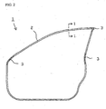
- Automobiles are provided with open-and-close front doors and a weather strip 1 is installed along the outer periphery of such a front door as shown in Fig. 2 .
- the greater part of the weather strip 1 along the longer direction is formed by an extrusion molding portion 2.
- corner portions are formed with die-molded sections 3.
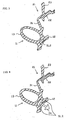
- the extrusion-molded portion 2 in the upper side portion has a main seal member 11 as a first seal member, a sub-seal member 21 as a second seal member and a coupling portion 31 for coupling both the seal members 11 and 21.
- the main seal member 11 has a substantially flat platelike first fitting base portion 12 fitted to the first retainer 41 of a door frame 40, and a hollow seal portion 13 formed integrally with the first fitting base portion 12 and protruded in an expanded condition toward the open peripheral edge of a body 42.
- the hollow seal portion 13 is formed of EPDM (ethylene-diene-propylene copolymer) sponge rubber.
- the sub-seal member 21 has a substantially flat platelike second fitting base portion 22 fitted to a second retainer 43 positioned on the outer body side of the first retainer 41, and a seal lip 23 formed integrally with the second fitting base portion 22 and projected toward the open peripheral edge of the body 42.
- the seal lip 23 is formed of EPDM (ethylene-diene-propylene copolymer) sponge rubber. More specifically, the seal lip 23, the coupling portion 31 and the hollow seal portion 13 are formed of EPDM sponge rubber consecutively by monolithic molding.
- the hollow seal portion 13 and the seal lip 23 come into contact with the open peripheral edge of the body 42 and are deformed when the front door is shut whereby to seal up the gap between the body 42 and the front door (door frame 40).
- the greater part of the substantially flat platelike second fitting base portion 22 of the sub-seal member 21 is formed of EPDM solid rubber as a solid material according to the embodiment of the invention.
- the one-side (on the outer body side) is made to be inserted into a mating depression in the latching part on the outer body side (in the right upper portion of Fig. 1 ) of the second retainer 43 and securely latched inside, whereas the side portion on the side of the main seal member 11 is made not to be so securely latched.
- the greater part is formed of the EPDM sponge rubber.
- the region visually confirmable from the outside is totally formed of the EPDM sponge rubber, so that it is attempted to prevent the quality of the external appearance from being deteriorated because of a difference in material.
- the central part of the first fitting base portion 12 (the portion shown by SL1 in Fig. 1 ) is formed of the EPDM solid rubber as well.
- the central part is a part that is not directly related to sealing and both its sides, that is, the portion directed related to the latching with respect to the first retainer 41, are formed of the EPDM sponge rubber.
- the ratio of the cross section of the portion formed of the solid material out of the first fitting base portion 12 to the cross section of the portion formed of the solid material out of the second fitting base portion 22 is set to not less than one third and not greater than one.
- the main seal member 11 and the sub-seal member 21 are integrated via the coupling portion 31 according to the embodiment of the invention, so that the number of man-hours necessary for the manufacture of them is reducible in comparison with a case where they are separately molded.
- the greater part of the second fitting base portion 22 is formed of the EPDM solid rubber. Consequently, by relatively securely inserting the side portion on the outer body side of the second fitting base portion 22 into the depression of the second retainer 43 without securely latching the other side portion on the side of the main seal member 11, the main seal member 11 is relatively securely fitted to the first retainer 41, so that the installed condition of the weather strip as a whole can be maintained with stability. Therefore, the installation work is greatly simplified by adopting an installation mode like this.
- the greater part of the second fitting base portion 22 is formed of the EPDM solid rubber
- the central part of the first fitting base portion 12 is also formed of the EPDM solid rubber according to the embodiment of the invention.
- the EPDM solid rubber is especially provided in the central part not directly related to installation as well as sealing out of the first fitting base portion 12 and any portion other than the central part is formed of the EPDM sponge rubber. Therefore, both sides of the first fitting base portion 12 are relatively easily subjected to deformation and can be fitted to the first retainer 41 without any impediment in particular.
- the region visually confirmable from the outside is totally formed of the EPDM sponge rubber, whereby nonconformity resulting from the lowering of the quality of the external appearance caused by employing different material is made preventable.
- the coupling portion 31 for coupling them 11 and 21 is formed of the EPDM sponge rubber according to the embodiment of the invention, so that the coupling portion 31 is excellent in follow-up characteristic as it is relatively easy to elongate. Assuming that a number of installation errors exist in regard to the first retainer 41 and the second retainer 43, installation can be completed with a sufficient time margin on absorbing such errors. Consequently, it is ensured that the installation workability is prevented from being deteriorated and even after the installation, the stabilization of the installed condition can be attempted.
- any other solid material or fine foaming material may be employed; more specifically, what has a hardness of not less than 65 degrees and not greater than 85 degrees in the JIS-A type is preferable and in the case of the fine foaming material, what has a foaming quantity of not greater than 25% is preferable.
- raw material TPO, PP and so on are enumerated.
Landscapes
- Engineering & Computer Science (AREA)
- Mechanical Engineering (AREA)
- Seal Device For Vehicle (AREA)
Claims (4)
- Dichtungsstreifen mit
einem ersten Dichtungselement (11) mit einem ersten Basisanschlussbereich (12) und einem Haüptdichtungsbereich (13), der integral mit dem ersten Basisanschlussbereich (12) ausgebildet ist, der in Form einer im Wesentlichen flachen Platte bereitgestellt ist, wobei der Hauptdichtungsbereich (13) durch einen Hohldichtungsbereich gebildet ist, der integral mit dem ersten Basisanschlussbereich ausgebildet ist, und wobei zumindest beide Seiten des ersten Basisanschlussbereichs so mit einem Anschlusselement (41) verriegelt sind, dass sie fest angebracht sind;
einem zweiten Dichtungselement (21), das einen zweiten Basisanschlussbereich (22) und einen Hilfsdichtungsbereich (23) aufweist, der aus Schaummaterial integral mit dem zweiten Basisanschlussbereich ausgebildet ist, wobei der zweite Basisanschlussbereich (22) in der Form einer im Wesentlichen flachen Platte bereitgestellt ist und der Hilfsdichtungsbereich (23) durch eine Dichtungslippe gebildet ist, die integral mit dem zweiten Basisanschlussbereich ausgebildet ist, und
einem Verbindungsbereich (31) zum Verbinden des ersten Dichtungselements (11) und des zweiten Dichtungselements (21),
dadurch gekennzeichnet, dass ein Großteil des oder der gesamte zweite Basisanschlussbereich (22) aus massivem Material oder feinem Schaummaterial ausgebildet ist, der Hauptdichtungsbereich und der Hilfsdichtungsbereich (23) aus Schaummaterial ausgebildet sind, ein Teil des ersten Basisanschlussbereichs (12), der, nachdem er installiert ist, nicht in direktem Kontakt mit dem Anschlusselement ist und beim Abdichten nicht in Kontakt mit einem gegenüberliegenden Element ist, aus dem massiven Material oder dem feinen Schaummaterial ausgebildet ist, und wobei ein Verhältnis aus einem Querschnitt des Bereichs aus dem massiven Material oder dem feinen Schaummaterial des zweiten Basisanschlussbereichs (22) zu einem Querschnitt des Bereichs aus dem massivem Material oder dem feinen Schaummaterial des ersten Basisanschlussbereichs (12) nicht weniger als ein Drittel und nicht größer als Eins ist, und
zumindest eine der Seiten des ersten Basisanschlussbereichs (12) aus dem Schaummaterial ausgebildet ist. - Dichtungsstreifen nach Anspruch 1, bei dem eine Oberfläche des ersten (12) und zweiten (22) Basisanschlussbereichs, die in einem montierten Zustand von außen sichtbar ist, aus dem Schaummaterial ausgebildet ist.
- Dichtungsstreifen nach einem der Ansprüche 1 oder 2, bei dem der Verbindungsbereich (31) aus dem Schaummaterial ausgebildet ist.
- Dichtungsstreifen nach einem der Ansprüche 1 bis 3, bei dem der erste Basisanschlussbereich (12) durch eine Klammer (44) verriegelt ist und ein Teil, der nach dem Montieren nicht in Kontakt mit der Klammer ist, aus dem massiven Material oder dem feinen Schaummaterial ausgebildet ist.
Applications Claiming Priority (2)
| Application Number | Priority Date | Filing Date | Title |
|---|---|---|---|
| JP2003419095 | 2003-12-17 | ||
| JP2003419095A JP4292975B2 (ja) | 2003-12-17 | 2003-12-17 | ウエザストリップ |
Publications (3)
| Publication Number | Publication Date |
|---|---|
| EP1544016A2 EP1544016A2 (de) | 2005-06-22 |
| EP1544016A3 EP1544016A3 (de) | 2007-07-18 |
| EP1544016B1 true EP1544016B1 (de) | 2010-02-10 |
Family
ID=34510630
Family Applications (1)
| Application Number | Title | Priority Date | Filing Date |
|---|---|---|---|
| EP04029884A Expired - Lifetime EP1544016B1 (de) | 2003-12-17 | 2004-12-16 | KFZ-Dichtungsprofil |
Country Status (5)
| Country | Link |
|---|---|
| US (1) | US20050136199A1 (de) |
| EP (1) | EP1544016B1 (de) |
| JP (1) | JP4292975B2 (de) |
| CN (1) | CN100360329C (de) |
| DE (1) | DE602004025446D1 (de) |
Families Citing this family (10)
| Publication number | Priority date | Publication date | Assignee | Title |
|---|---|---|---|---|
| JP2008184040A (ja) * | 2007-01-30 | 2008-08-14 | Toyoda Gosei Co Ltd | ドアウエザストリップ |
| JP2008184092A (ja) * | 2007-01-31 | 2008-08-14 | Toyoda Gosei Co Ltd | ドアウエザストリップ及びその製造方法 |
| JP5057237B2 (ja) * | 2008-04-24 | 2012-10-24 | 豊田合成株式会社 | 自動車用ドアウエザストリップ |
| JP5110382B2 (ja) * | 2008-07-31 | 2012-12-26 | 豊田合成株式会社 | ドアウエザストリップの製造方法 |
| US8701352B2 (en) * | 2011-09-15 | 2014-04-22 | Ford Global Technologies, Llc | Two-shot secondary seal with clip |
| JP6429524B2 (ja) * | 2014-07-30 | 2018-11-28 | 鬼怒川ゴム工業株式会社 | ドアウエザーストリップ |
| JP6902927B2 (ja) * | 2017-05-23 | 2021-07-14 | 西川ゴム工業株式会社 | 自動車用グラスランの取付構造 |
| JP6858740B2 (ja) | 2018-11-29 | 2021-04-14 | 西川ゴム工業株式会社 | ウェザーストリップ、ウェザーストリップの取付構造、およびウェザーストリップの取付方法 |
| CN112124056A (zh) * | 2020-10-19 | 2020-12-25 | 建新赵氏科技有限公司 | 一种双c型密封条结构 |
| KR102700262B1 (ko) * | 2023-06-26 | 2024-08-29 | 케이지모빌리티 주식회사 | 차량용 도어 프레임의 조립 구조 |
Family Cites Families (14)
| Publication number | Priority date | Publication date | Assignee | Title |
|---|---|---|---|---|
| GB2200390B (en) * | 1987-01-23 | 1991-04-10 | Draftex Ind Ltd | A closure sealing arrangement |
| JPH0714043Y2 (ja) * | 1989-09-30 | 1995-04-05 | 豊田合成株式会社 | ガラスラン |
| FR2670162A1 (fr) * | 1990-12-07 | 1992-06-12 | Hutchinson Sa | Dispositif d'etancheite pour cadre de baie a vitre coulissante ou fixe. |
| JP2543917Y2 (ja) * | 1991-07-10 | 1997-08-13 | 豊田合成株式会社 | ウェザストリップ |
| JP2988192B2 (ja) * | 1992-08-24 | 1999-12-06 | 豊田合成株式会社 | 自動車用ルーフサイドウエザストリップ |
| GB2296522B (en) * | 1994-12-29 | 1998-02-18 | Standard Prod Ltd | Sealing device |
| JPH08216687A (ja) * | 1995-02-16 | 1996-08-27 | Nishikawa Rubber Co Ltd | ドアウエザーストリップ |
| US5950366A (en) * | 1997-04-21 | 1999-09-14 | General Motors Corporation | Seal structure for removable roof |
| JPH10324160A (ja) * | 1997-05-26 | 1998-12-08 | Nishikawa Rubber Co Ltd | ウェザストリップ |
| JP3861606B2 (ja) * | 2001-02-21 | 2006-12-20 | 豊田合成株式会社 | 自動車用ウエザストリップ |
| JP3879420B2 (ja) * | 2001-03-21 | 2007-02-14 | 豊田合成株式会社 | ウエザーストリップ及びその取付構造 |
| JP2002307952A (ja) * | 2001-04-12 | 2002-10-23 | Toyo Tire & Rubber Co Ltd | ドアウエザストリップの取付構造 |
| US6601246B2 (en) * | 2001-07-31 | 2003-08-05 | Conair Corporation | Bubbling bath mat |
| JP3626125B2 (ja) * | 2001-09-04 | 2005-03-02 | 本田技研工業株式会社 | 自動車用サッシュドアのモール取付構造 |
-
2003
- 2003-12-17 JP JP2003419095A patent/JP4292975B2/ja not_active Expired - Lifetime
-
2004
- 2004-12-16 DE DE602004025446T patent/DE602004025446D1/de not_active Expired - Lifetime
- 2004-12-16 EP EP04029884A patent/EP1544016B1/de not_active Expired - Lifetime
- 2004-12-16 US US11/012,727 patent/US20050136199A1/en not_active Abandoned
- 2004-12-17 CN CNB2004100818524A patent/CN100360329C/zh not_active Expired - Fee Related
Also Published As
| Publication number | Publication date |
|---|---|
| CN100360329C (zh) | 2008-01-09 |
| CN1629000A (zh) | 2005-06-22 |
| US20050136199A1 (en) | 2005-06-23 |
| JP2005178455A (ja) | 2005-07-07 |
| JP4292975B2 (ja) | 2009-07-08 |
| EP1544016A3 (de) | 2007-07-18 |
| DE602004025446D1 (de) | 2010-03-25 |
| EP1544016A2 (de) | 2005-06-22 |
Similar Documents
| Publication | Publication Date | Title |
|---|---|---|
| CA1322216C (en) | Window pane sealing strip having a rigid non-reinforced glass-run channel | |
| US6679003B2 (en) | Door frame structure of motor vehicle | |
| US7685777B2 (en) | Weather strip for motor vehicle | |
| US10549618B2 (en) | Weather strip | |
| US7578098B2 (en) | Door weather strip for motor vehicle | |
| EP1544016B1 (de) | KFZ-Dichtungsprofil | |
| US20040216384A1 (en) | Door weather strip | |
| US7172239B2 (en) | Sealing structure for vehicle door | |
| JP4788909B2 (ja) | ガラスラン | |
| US6647667B2 (en) | Trim and seal member | |
| US5106149A (en) | Weatherstrip for hardtop-type or framed door windows | |
| US20040088925A1 (en) | Door seal structure of motor vehicle | |
| US6969111B2 (en) | Sealing structure of sliding roof of motor vehicle | |
| US8807641B2 (en) | Roof weather strip for motor vehicle | |
| US20030159358A1 (en) | Weather strip for motor vehicle | |
| JP4924894B2 (ja) | ドアウエザストリップ | |
| CN119384365A (zh) | 密封型材条和用于滑动窗的密封装置 | |
| JP2002240565A (ja) | 自動車用ドア | |
| US6112468A (en) | Door weatherstripping for motor vehicle and method of manufacturing the same | |
| JP2006298204A (ja) | ウエザストリップ | |
| JP4062530B2 (ja) | 自動車用スライドウインドガラスラン | |
| JP7437224B2 (ja) | 自動車用シール材 | |
| JP2011025855A (ja) | 自動車用ドアの吸い出され防止構造 | |
| JP4238704B2 (ja) | ウエザーストリップ | |
| JP3707344B2 (ja) | トリム及びシール部品 |
Legal Events
| Date | Code | Title | Description |
|---|---|---|---|
| PUAI | Public reference made under article 153(3) epc to a published international application that has entered the european phase |
Free format text: ORIGINAL CODE: 0009012 |
|
| 17P | Request for examination filed |
Effective date: 20041216 |
|
| AK | Designated contracting states |
Kind code of ref document: A2 Designated state(s): AT BE BG CH CY CZ DE DK EE ES FI FR GB GR HU IE IS IT LI LT LU MC NL PL PT RO SE SI SK TR |
|
| AX | Request for extension of the european patent |
Extension state: AL BA HR LV MK YU |
|
| PUAL | Search report despatched |
Free format text: ORIGINAL CODE: 0009013 |
|
| AK | Designated contracting states |
Kind code of ref document: A3 Designated state(s): AT BE BG CH CY CZ DE DK EE ES FI FR GB GR HU IE IS IT LI LT LU MC NL PL PT RO SE SI SK TR |
|
| AX | Request for extension of the european patent |
Extension state: AL BA HR LV MK YU |
|
| 17Q | First examination report despatched |
Effective date: 20070927 |
|
| AKX | Designation fees paid |
Designated state(s): DE FR GB |
|
| GRAP | Despatch of communication of intention to grant a patent |
Free format text: ORIGINAL CODE: EPIDOSNIGR1 |
|
| GRAS | Grant fee paid |
Free format text: ORIGINAL CODE: EPIDOSNIGR3 |
|
| RIN1 | Information on inventor provided before grant (corrected) |
Inventor name: AOKI, SHIGENORIC/O TOYODA GOSEI CO., LTD. Inventor name: YOSHIOKA, SHINICHIC/O TOYODA GOSEI CO., LTD. Inventor name: SUZUKI, SATOSHIC/O TOYODA GOSEI CO., LTD. Inventor name: MORITA, TAKAFUMIC/O TOYODA GOSEI CO., LTD. |
|
| GRAA | (expected) grant |
Free format text: ORIGINAL CODE: 0009210 |
|
| AK | Designated contracting states |
Kind code of ref document: B1 Designated state(s): DE FR GB |
|
| REG | Reference to a national code |
Ref country code: GB Ref legal event code: FG4D |
|
| REF | Corresponds to: |
Ref document number: 602004025446 Country of ref document: DE Date of ref document: 20100325 Kind code of ref document: P |
|
| PLBE | No opposition filed within time limit |
Free format text: ORIGINAL CODE: 0009261 |
|
| STAA | Information on the status of an ep patent application or granted ep patent |
Free format text: STATUS: NO OPPOSITION FILED WITHIN TIME LIMIT |
|
| 26N | No opposition filed |
Effective date: 20101111 |
|
| REG | Reference to a national code |
Ref country code: GB Ref legal event code: 746 Effective date: 20131017 |
|
| REG | Reference to a national code |
Ref country code: DE Ref legal event code: R084 Ref document number: 602004025446 Country of ref document: DE Effective date: 20131022 |
|
| REG | Reference to a national code |
Ref country code: FR Ref legal event code: PLFP Year of fee payment: 12 |
|
| REG | Reference to a national code |
Ref country code: FR Ref legal event code: PLFP Year of fee payment: 13 |
|
| REG | Reference to a national code |
Ref country code: FR Ref legal event code: PLFP Year of fee payment: 14 |
|
| PGFP | Annual fee paid to national office [announced via postgrant information from national office to epo] |
Ref country code: DE Payment date: 20191203 Year of fee payment: 16 |
|
| PGFP | Annual fee paid to national office [announced via postgrant information from national office to epo] |
Ref country code: GB Payment date: 20191213 Year of fee payment: 16 |
|
| PGFP | Annual fee paid to national office [announced via postgrant information from national office to epo] |
Ref country code: FR Payment date: 20201112 Year of fee payment: 17 |
|
| REG | Reference to a national code |
Ref country code: DE Ref legal event code: R119 Ref document number: 602004025446 Country of ref document: DE |
|
| GBPC | Gb: european patent ceased through non-payment of renewal fee |
Effective date: 20201216 |
|
| PG25 | Lapsed in a contracting state [announced via postgrant information from national office to epo] |
Ref country code: DE Free format text: LAPSE BECAUSE OF NON-PAYMENT OF DUE FEES Effective date: 20210701 Ref country code: GB Free format text: LAPSE BECAUSE OF NON-PAYMENT OF DUE FEES Effective date: 20201216 |
|
| PG25 | Lapsed in a contracting state [announced via postgrant information from national office to epo] |
Ref country code: FR Free format text: LAPSE BECAUSE OF NON-PAYMENT OF DUE FEES Effective date: 20211231 |