EP1543255B1 - Arbres rotatifs a amortisseur de torsion - Google Patents
Arbres rotatifs a amortisseur de torsion Download PDFInfo
- Publication number
- EP1543255B1 EP1543255B1 EP03748283A EP03748283A EP1543255B1 EP 1543255 B1 EP1543255 B1 EP 1543255B1 EP 03748283 A EP03748283 A EP 03748283A EP 03748283 A EP03748283 A EP 03748283A EP 1543255 B1 EP1543255 B1 EP 1543255B1
- Authority
- EP
- European Patent Office
- Prior art keywords
- inertia mass
- axis
- shaft
- cavity
- housing
- Prior art date
- Legal status (The legal status is an assumption and is not a legal conclusion. Google has not performed a legal analysis and makes no representation as to the accuracy of the status listed.)
- Expired - Lifetime
Links
- 239000004519 grease Substances 0.000 claims abstract description 13
- 239000000463 material Substances 0.000 claims abstract description 12
- 230000007423 decrease Effects 0.000 claims abstract description 9
- 239000012858 resilient material Substances 0.000 claims description 10
- 239000007788 liquid Substances 0.000 claims description 9
- 239000012530 fluid Substances 0.000 description 11
- 238000005086 pumping Methods 0.000 description 7
- 229920001971 elastomer Polymers 0.000 description 6
- 239000013536 elastomeric material Substances 0.000 description 6
- 238000013016 damping Methods 0.000 description 5
- 229920001296 polysiloxane Polymers 0.000 description 5
- RYGMFSIKBFXOCR-UHFFFAOYSA-N Copper Chemical compound [Cu] RYGMFSIKBFXOCR-UHFFFAOYSA-N 0.000 description 4
- 230000001133 acceleration Effects 0.000 description 4
- 238000010276 construction Methods 0.000 description 4
- 229910052802 copper Inorganic materials 0.000 description 4
- 239000010949 copper Substances 0.000 description 4
- 230000035939 shock Effects 0.000 description 4
- 230000000694 effects Effects 0.000 description 3
- 239000007787 solid Substances 0.000 description 2
- 229910000831 Steel Inorganic materials 0.000 description 1
- 230000015556 catabolic process Effects 0.000 description 1
- 230000006835 compression Effects 0.000 description 1
- 238000007906 compression Methods 0.000 description 1
- 230000003247 decreasing effect Effects 0.000 description 1
- 238000006731 degradation reaction Methods 0.000 description 1
- 125000000118 dimethyl group Chemical group [H]C([H])([H])* 0.000 description 1
- 238000006073 displacement reaction Methods 0.000 description 1
- 239000000806 elastomer Substances 0.000 description 1
- 239000000446 fuel Substances 0.000 description 1
- 230000007774 longterm Effects 0.000 description 1
- 239000000314 lubricant Substances 0.000 description 1
- 239000000203 mixture Substances 0.000 description 1
- 230000007935 neutral effect Effects 0.000 description 1
- 239000002245 particle Substances 0.000 description 1
- 230000002093 peripheral effect Effects 0.000 description 1
- 230000007425 progressive decline Effects 0.000 description 1
- 230000000750 progressive effect Effects 0.000 description 1
- 230000002441 reversible effect Effects 0.000 description 1
- 239000011343 solid material Substances 0.000 description 1
- 239000010959 steel Substances 0.000 description 1
Images


Classifications
-
- F—MECHANICAL ENGINEERING; LIGHTING; HEATING; WEAPONS; BLASTING
- F16—ENGINEERING ELEMENTS AND UNITS; GENERAL MEASURES FOR PRODUCING AND MAINTAINING EFFECTIVE FUNCTIONING OF MACHINES OR INSTALLATIONS; THERMAL INSULATION IN GENERAL
- F16F—SPRINGS; SHOCK-ABSORBERS; MEANS FOR DAMPING VIBRATION
- F16F15/00—Suppression of vibrations in systems; Means or arrangements for avoiding or reducing out-of-balance forces, e.g. due to motion
- F16F15/10—Suppression of vibrations in rotating systems by making use of members moving with the system
- F16F15/16—Suppression of vibrations in rotating systems by making use of members moving with the system using a fluid or pasty material
- F16F15/167—Suppression of vibrations in rotating systems by making use of members moving with the system using a fluid or pasty material having an inertia member, e.g. ring
- F16F15/173—Suppression of vibrations in rotating systems by making use of members moving with the system using a fluid or pasty material having an inertia member, e.g. ring provided within a closed housing
-
- F—MECHANICAL ENGINEERING; LIGHTING; HEATING; WEAPONS; BLASTING
- F16—ENGINEERING ELEMENTS AND UNITS; GENERAL MEASURES FOR PRODUCING AND MAINTAINING EFFECTIVE FUNCTIONING OF MACHINES OR INSTALLATIONS; THERMAL INSULATION IN GENERAL
- F16F—SPRINGS; SHOCK-ABSORBERS; MEANS FOR DAMPING VIBRATION
- F16F15/00—Suppression of vibrations in systems; Means or arrangements for avoiding or reducing out-of-balance forces, e.g. due to motion
- F16F15/28—Counterweights, i.e. additional weights counterbalancing inertia forces induced by the reciprocating movement of masses in the system, e.g. of pistons attached to an engine crankshaft; Attaching or mounting same
- F16F15/283—Counterweights, i.e. additional weights counterbalancing inertia forces induced by the reciprocating movement of masses in the system, e.g. of pistons attached to an engine crankshaft; Attaching or mounting same for engine crankshafts
-
- Y—GENERAL TAGGING OF NEW TECHNOLOGICAL DEVELOPMENTS; GENERAL TAGGING OF CROSS-SECTIONAL TECHNOLOGIES SPANNING OVER SEVERAL SECTIONS OF THE IPC; TECHNICAL SUBJECTS COVERED BY FORMER USPC CROSS-REFERENCE ART COLLECTIONS [XRACs] AND DIGESTS
- Y10—TECHNICAL SUBJECTS COVERED BY FORMER USPC
- Y10T—TECHNICAL SUBJECTS COVERED BY FORMER US CLASSIFICATION
- Y10T74/00—Machine element or mechanism
- Y10T74/21—Elements
- Y10T74/2173—Cranks and wrist pins
- Y10T74/2183—Counterbalanced
Definitions
- the present invention relates to rotary shafts and is concerned with such shafts which include a torsional vibration damper.
- rotary shafts are subjected to regular or intermittent torque fluctuations or shock loads.
- One example of such shafts is automotive crankshafts, which are subjected to a shock torque loading twice per revolution, in the case of a four cylinder engine, that is to say each time ignition of the fuel/air mixture in one of the cylinders occurs.
- shock loads can dramatically reduce the useful service of rotary shafts and can result in their sudden catastrophic failure, if the shaft should go into torsional resonance.
- Resilient dampers (see e.g. US-A-1 928 119 ) comprise a relatively massive weight attached to one end of the shaft by a resilient connection of e.g. rubber of elastomeric material. Movement of the weight relative to the shaft shears the resilient element and dissipates vibration energy by hysteresis of the rubber.
- Viscous dampers comprise a housing connected to one end of the shaft to rotate with it. Inside the housing is a viscous fluid and a mass which is mounted on the shaft by way of a bearing so that it can rotate with respect to the shaft.
- both of these known dampers are provided at the end of the shaft and thus increase the effective length of the shaft.
- this is highly undesirable, particularly in the engine space of motor vehicles in which there is an ever increasing pressure on space.
- the fluid used in viscous dampers is typically silicone-based and such liquids are subject to progressive thermal degradation at the temperatures to which e.g. crankshafts are typically subjected and this results in a progressive decrease over time in the effectiveness of the known dampers. Similar comments also applied historically to the resilient materials typically used in resilient dampers.
- the object of the present invention to provide a rotary shaft, particularly a shaft which forms part of an engine, such as a crankshaft, with a vibration damper which does not suffer from the disadvantages referred to above.
- a rotary shaft such as an engine crankshaft, for rotation about an axis carries an eccentric, substantially circular section, radially extending flange, connected to the radially outer surface of which is an annular housing affording a cavity defined in part by radially inner and radially outer coaxial cylindrical surfaces, the axis of which is offset from the axis of the shaft, the cavity accommodating an annular inertia mass, the radially inner and radially outer surfaces of the cavity being opposed to radially inner and radially outer surfaces, respectively, of the inertia mass, whereby there are two pairs of opposed surfaces, one of the said pairs constituting bearing surfaces guiding relative rotation of the inertia mass and the housing about the axis of the coaxial cylindrical surfaces, the other of the said pairs being spaced apart to define an annular space accommodating a displaceable material, the inertia mass and the cavity having a dimension in the radial direction which has a maximum value at a first position opposite to
- the shaft in accordance with the invention includes a torsional damper at any desired position between its ends and the damper need not be provided at one end of the shaft, thereby necessitating an increase in its length. This is of particular value when the shaft is an engine crankshaft.
- the eccentric flange may be constituted by one of the crankwebs which is in any event traditionally provided on crankshafts.
- the shaft carries an eccentric flange and the eccentricity of the flange results in its having a radial dimension which varies circumferentially. This radial dimension is at a maximum in one direction, the so-called direction of eccentricity, and decreases progressively in both circumferential directions to a second position offset from the first position by 180°.
- an annular housing Connected to the outer surface of the eccentric flange is an annular housing which defines an annular cavity accommodating an annular inertia mass.
- the inertia mass has radially inner and radially outer cylindrical surfaces, the axis of which is offset from the axis of the shaft.
- the radially inner and outer surfaces of the cavity are opposed to radially inner and radially outer surfaces, respectively, of the inertia mass, whereby there are two pairs of exposed surfaces.
- One of these pairs of surfaces are relatively closely spaced and constitute bearing surfaces guiding relative rotation of the inertia mass and the housing about the axis of the cylindrical surfaces.
- the other of the pairs of surfaces is spaced apart, e.g. by between 1 mm and 2 mm, to define an annular space. This space accommodates a displaceable material and in the preferred embodiment this material is a viscous fluid, e.g. a grease.
- the inertia mass and the cavity have a dimension in the radial direction which has a maximum value at a first position opposite the direction of eccentricity and decreases progressively in both circumferential directions to a second position offset by 180° from the first position.
- the mass of the housing and the inertia mass and their weight distribution are set to counterbalance the eccentric flange and may additionally counterbalance a portion of the crankpin and connecting rod. The heavier portion of the housing and inertia mass thus replace the conventional counterweight on a crankshaft.
- the shaft should be subjected to a fluctuating or impact torque, it will accelerate or decelerate and the inertia of the inertia mass, which is movably accommodated in the cavity in the housing, will result in its acceleration lagging that of the shaft.
- the inertia mass will thus rotate within the cavity about the axis of the pairs of opposed surfaces and not about the axis of the crankshaft. This will result in the space between the pair of spaced surfaces increasing in width on one side and decreasing in width on the other. This will result in turn in the fluid being displaced or pumped from the area of reduced width to the area of increased width. Due to the viscosity of the liquid, this displacement will incur substantial pumping losses.
- the viscous fluid has a viscosity in the range of 5.000 to 25,000, more preferably 10,000 to 15,000, centistokes, which is very much lower than the value of 100,000 to 300,000 centistokes, which is the typical viscosity range of the silicone fluids traditionally used in viscous dampers.
- the displaceable material comprises a resilient solid material of e.g. rubber or elastomeric material.
- the material cannot be displaced from positions where the space is of minimum width to positions where it is of maximum width but it can be displaced a certain distance in the circumferential direction and is subjected to alternating compression and relaxation at positions which will move circumferentially back and forth.
- the hysteresis losses suffered by the resilient annular member will therefore be substantially in excess of those in the resilient member in a conventional resilient vibration damper and the damping effect will be thereby enhanced.
- the housing includes a cover plate which closes the cavity and extends in a radial plane.
- the inertia mass may potentially become jammed in one or other of its extreme positions after it has rotated in the housing and this may be prevented by the provision of two end stops.
- the inertia mass may then return readily to its rest or central position under the action of the forces to which it is subjected but it may be desirable to provide spring means acting on the inertia mass and biasing it towards a position in which the radial width of the space is constant.
- the spring means may take the form of one or more springs of conventional type, e.g. coil springs, extending between the housing and the inertia mass and it may also take the form of an annular member of elastomeric material connected between the two cylindrical surfaces defining the space. In this event, the elastomeric material need not occupy the whole of the space and the remainder may be occupied by a viscous liquid.
- the imbalance caused by the eccentricity of the flange is counterbalanced by the asymmetrical construction of the housing and inertia mass.
- an automotive crankshaft for rotation about an axis carries at least one pair of axially spaced, radially extending eccentric crankwebs, at least one of which has a circular cylindrical radially outer surface, the axis of which is offset from the axis of the crankshaft, and connected to which is the inner surface of an annular member of resilient material, connected to the outer surface of which is the cylindrical inner surface of an annular inertia mass, the weight distribution of which counterbalances the eccentricity of the associated crankweb.
- this embodiment is similar to that referred to above, but since a solid resilient material is used, the housing has been omitted and the integrity of the damper is ensured by connecting the annular member of resilient material to both the eccentric flange and the inertia mass.
- the inertia mass is again heavier on the side opposite to the direction of eccentricity but since it is not accommodated in a space within a housing, its size need not decrease progressively but may decrease abruptly. Its weight distribution is simply selected such that it counterbalances the associated crankweb, whereby the crankshaft is dynamically balanced.
- the inner surface of the resilient material may be connected directly to the external surface of the crankweb or indirectly via a metallic sleeve secured, e.g. by press-fitting or force-fitting, to the crankweb.
- FIG. 1 shows a crankshaft 2, which is mounted to rotate about an axis 4 and carries a number of pairs of spaced crankwebs 6, in the usual manner.
- the number of pairs of crankwebs 6 will be equal to the number of pistons to which the crankshaft is connected but in this case only one such pair is shown.
- Each crankweb 6 has a circular peripheral surface and is eccentrically positioned on the crankshaft such that the centre of the circle is at a point 8, which is offset from the axis 4 by a predetermined distance in the direction of eccentricity.
- Extending between the eccentric portions of the pair of crankwebs is a crankpin 10 which is pivotally connected in the conventional manner to one end of a connecting rod 12, the other end of which is pivotally connected in the conventional manner to a piston 14.
- each crankweb 6 Connected to the external surface of each crankweb 6 is an annular housing 16 defining a rectangular section internal cavity which is accessible by way of a lateral cover 18.
- an inertia mass 20 Accommodated within the cavity is an inertia mass 20 of steel or the like.
- the housing 16, the cavity within it and the inertia mass 20 are all of annular shape with a radial dimension that is a maximum at a first position on the side opposite to the direction of eccentricity of the crankwebs and reduces progressively in both directions to a second position that is offset from the first position by 180°.
- the housing 16 and the inertia mass 20 are of relatively massive construction and are thus substantially heavier on the side opposite to the direction of eccentricity.
- crankwebs are dimensioned such that the heavier portions of the housing and inertia mass counterbalance the eccentricity of the crankwebs so that the crankshaft is dynamically and statically balanced. It will be seen that, for this purpose, it may be necessary, as in the present case, for the housing 16 to be wider, that is to say have a greater dimension in the axial direction, than the associated crankweb.
- the radially inner surface of the annular cavity is of circular section and is opposed to the internal surface of the inertia mass 20, which is also of substantially circular section. These two surfaces are of substantially the same diameter and have a clearance between them, typically of only about 0.025 mm when the inertia mass has an external diameter of about 100 to 150 mm, and thus act as bearing surfaces.
- the radially outer surface of the cavity is also of circular section and is opposed to the coaxial radially outer surface of the inertia mass. Both of these surfaces are of circular section, whose centres are at a point 22 slightly offset from the axis 4 of the crankshaft and whose diameters differ by a small amount of typically 1 to 2 mm.
- An annular space 24 is thus defined between these two surfaces which is occupied by a viscous fluid.
- This may be copper grease, that is to say a grease containing metallic copper particles, and is preferably a dimethyl silicone grease as supplied by Nye Lubricants, Inc.
- the housing and the inertia mass within it rotate with, and at the same speed as, the shaft. If, however, the shaft should be subjected to a shock torque tending to increase its speed, the inertia of the inertia mass will mean that the mass will not accelerate at the same rate as the shaft. The inertia mass will therefore start to rotate within the housing, with relative movement occurring at the opposed bearing surfaces.
- the space 24 filled with the copper grease will not remain of constant width, as previously, and instead its width will increase on one side and decrease on the other side, as shown in Figure 2.
- the outer surfaces of the inertia mass 20 and of the cavity in the housing 16 are closely spaced and act as the bearing surfaces and the space 24 occupied by grease is defined between the inner surfaces of the inertia mass and the cavity.
- This embodiment operates in precisely the same manner as the first embodiment.
- the inertia mass will typically rotate between 0.5° and 2° but under intense acceleration may rotate between about 3° and 5° relative to the housing until the inertia mass contacts a stop member on the housing or until the opposed surfaces defining the space 24 come into contact, as illustrated in Figures 2 and 3. Further rotary movement in the same direction is then impossible.
- a portion 30 of inertia mass 20 opposite to the direction of eccentricity is of increased thickness in the axial direction and at its end the portion 30 affords oppositely circumferentially directed shoulders 32. These shoulders 32 are opposed to similar shoulders 34 on the crankwebs. Secured to or adjacent, and extending between, the opposed pairs of shoulders 32, 34 is a return spring 36, as shown on the left in Figure 5, or two return springs 36, as shown on the right of Figure 5.
- the axial end surfaces of the inertia mass 20 are smooth and closely spaced from the opposed surfaces of the cavity.
- one or both of these surfaces are provided with a number of thrust pads 38 which are closely spaced from the opposed surface of the cavity.
- the space 24 is occupied by a displaceable material in the form of a viscous liquid and the damping effect is achieved by virtue of shear forces and pumping losses.
- All of these embodiments may be modified by replacing the viscous liquid by a body of resilient material e.g. rubber or an elastomer. In this case, no pumping occurs but the resilient material is repeatedly compressed and decompressed as a result of the variation in the thickness distribution of the space 24 and damping is achieved by virtue of the resilience of the material and hysteresis losses.
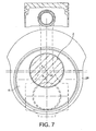
- the use of resilient material permits the construction to be modified and simplified and such a construction is illustrated in Figures 6 and 7.
- annular sleeve 40 Secured to the radially outer surface of the circular section eccentric crankwebs 6 by push-fitting or force-fitting is an annular sleeve 40. Secured to the outer surface of the sleeve 40 is the internal surface of a resilient ring 42 of resilient rubber or elastomeric material.
- the resilient material is resistant to temperatures of up to 250°C or more, e.g. as supplied by Metaldyne International. The material may be as disclosed in EP-A-0540818 or US 20020115813 .
- Secured to the outer surface of the elastomeric ring is the internal circular section surface of an inertia mass 20.
- the inertia mass 20 has a width in the radial direction which is relatively large over about one third of its circumference opposite to the direction of eccentricity and relatively small elsewhere.
- the inertia mass thus has a heavier portion 21 which acts as a counterweight to the eccentric crankweb 6.
- This vibration damper operates in a manner not dissimilar to the conventional resilient vibration damper but has two major differences. Firstly, it is situated, in use, within the crankcase and thus does not add to the overall length of the crankshaft, as is usual. Secondly, if rotary vibration should occur, the inertia mass 20 will rotate a small distance about the crankweb 6. Since this rotation is about the axis 8, which is offset from the axis 4 of the crankshaft, the width of the space accommodating the elastomeric ring 42 will vary locally, so the elastomeric material will be locally compressed and expanded. This will result in increased hysteresis losses and thus in an enhanced damping effect.
Landscapes
- Engineering & Computer Science (AREA)
- General Engineering & Computer Science (AREA)
- Physics & Mathematics (AREA)
- Acoustics & Sound (AREA)
- Aviation & Aerospace Engineering (AREA)
- Mechanical Engineering (AREA)
- Shafts, Cranks, Connecting Bars, And Related Bearings (AREA)
- Soil Working Implements (AREA)
- Vibration Dampers (AREA)
- Non-Portable Lighting Devices Or Systems Thereof (AREA)
- Water Treatment By Electricity Or Magnetism (AREA)
Claims (7)
- Arbre tournant (2) pour rotation autour d'un axe (4) et support d'un flasque de vilebrequin excentré, de section essentiellement circulaire, s'étendant radialement (6), raccordé à la surface radialement extérieure de ce qui est un logement annulaire (16) offrant une cavité définie en partie par des surfaces cylindriques radialement intérieure et radialement extérieure coaxiales, dont l'axe (8) est désaxé par rapport à l'axe de l'arbre (4), la cavité abritant une masse d'inertie annulaire (20), les surfaces radialement intérieure et radialement extérieure de la cavité étant opposées aux surfaces radialement intérieure et radialement extérieure, respectivement, de la masse d'inertie (20), en vertu de quoi il y a deux paires de surfaces opposées, l'une desdites paires constituant des surfaces de palier guidant la rotation relative de la masse d'inertie (20) et du logement (16) autour de l'axe des surfaces coaxiales cylindriques, l'autre desdites paires étant espacée l'une de l'autre pour définir un espace annulaire (24) abritant un matériau déplaçable, la masse d'inertie (20) et la cavité ayant une dimension dans la direction radiale qui a une valeur maximum à une première position opposée à la direction d'excentricité et qui diminue progressivement dans les deux directions circonférentielles vers une deuxième position de décalée de 180° de la première position.
- Arbre selon la revendication 1 dans lequel le matériau déplaçable est un liquide visqueux.
- Arbre selon la revendication 2 dans lequel le liquide visqueux comprend une graisse.
- Arbre selon la revendication 1 dans lequel le logement est fermé par une plaque couvercle (18) s'étendant dans un plan radial.
- Arbre selon l'une quelconque des revendications précédentes, incluant un moyen à ressort (36) agissant sur la masse d'inertie (20) et l'influençant vers une position dans laquelle la largeur radiale de l'espace est constante.
- Arbre selon l'une quelconque des revendications précédentes dans lequel l'épaisseur, dans la direction radiale de la partie du logement (16), opposée à la direction de l'excentricité, est plus grande que celle du flasque de vilebrequin excentré.
- Vilebrequin d'automobile (2) pour rotation autour d'un axe et support d'au moins une paire de bras de vilebrequin excentrés espacés axialement (16) se prolongeant radialement, dont au moins l'un d'eux a une surface extérieure radialement cylindrique circulaire, dont l'axe est désaxé par rapport à l'axe (4) du vilebrequin (2) et est raccordé à ce qui est la surface intérieure d'un élément annulaire en matériau élastique (42), raccordé à la surface extérieure de ce qui est la surface cylindrique intérieure d'une masse d'inertie annulaire (20), dont la répartition de poids contrebalance l'excentricité du bras de vilebrequin associé.
Applications Claiming Priority (3)
| Application Number | Priority Date | Filing Date | Title |
|---|---|---|---|
| GB0222480 | 2002-09-27 | ||
| GBGB0222480.6A GB0222480D0 (en) | 2002-09-27 | 2002-09-27 | Torsionally damped rotary shafts |
| PCT/GB2003/004055 WO2004029476A1 (fr) | 2002-09-27 | 2003-09-23 | Arbres rotatifs a amortisseur de torsion |
Publications (2)
| Publication Number | Publication Date |
|---|---|
| EP1543255A1 EP1543255A1 (fr) | 2005-06-22 |
| EP1543255B1 true EP1543255B1 (fr) | 2007-09-12 |
Family
ID=9944893
Family Applications (1)
| Application Number | Title | Priority Date | Filing Date |
|---|---|---|---|
| EP03748283A Expired - Lifetime EP1543255B1 (fr) | 2002-09-27 | 2003-09-23 | Arbres rotatifs a amortisseur de torsion |
Country Status (8)
| Country | Link |
|---|---|
| US (1) | US7584738B2 (fr) |
| EP (1) | EP1543255B1 (fr) |
| JP (1) | JP4302636B2 (fr) |
| AT (1) | ATE373181T1 (fr) |
| AU (1) | AU2003267591A1 (fr) |
| DE (2) | DE20321766U1 (fr) |
| GB (1) | GB0222480D0 (fr) |
| WO (1) | WO2004029476A1 (fr) |
Families Citing this family (12)
| Publication number | Priority date | Publication date | Assignee | Title |
|---|---|---|---|---|
| JP5160264B2 (ja) * | 2008-02-25 | 2013-03-13 | 本田技研工業株式会社 | エンジンのクランクシャフト機構 |
| JP2010090966A (ja) * | 2008-10-07 | 2010-04-22 | Kobe Steel Ltd | 制振構造 |
| DE102008053632B3 (de) * | 2008-10-29 | 2009-12-24 | Geislinger Gmbh | Drehschwingungsdämpfer und drehendes Bauteil mit Drehschwingungsdämpfer |
| DE102009046745A1 (de) * | 2009-11-17 | 2011-05-19 | Man Diesel & Turbo Se | Kurbelwelle |
| US8757027B2 (en) | 2010-09-01 | 2014-06-24 | Ford Global Technologies, Llc | Reduced mass crankshaft |
| DE102013203560B4 (de) * | 2013-03-01 | 2020-06-18 | Ford Global Technologies, Llc | Brennkraftmaschine mit auf der Kurbelwelle angeordnetem und als Unwucht dienendem Ausgleichsgewicht und Verfahren zur Herstellung der Kurbelwelle |
| JP5845497B2 (ja) * | 2013-03-08 | 2016-01-20 | 桂一 遠藤 | 衝撃吸収・エネルギー蓄積クランクシャフト |
| DE102013206931A1 (de) * | 2013-04-17 | 2014-10-23 | Ford Global Technologies, Llc | Brennkraftmaschine umfassend eine Kurbelwelle mit als Unwucht dienendem Ausgleichsgewicht und Verfahren zur Herstellung der Kurbelwelle |
| CN104295663A (zh) * | 2014-11-07 | 2015-01-21 | 广西玉柴机器股份有限公司 | 发动机的曲轴减振器 |
| DE102016001596A1 (de) * | 2016-02-11 | 2017-08-17 | Wabco Gmbh | Hubkolbenmaschine, insbesondere zwei- oder mehrstufiger Kolbenkompressor, Druckluftversorgungsanlage, Druckluftversorgungssystem und Fahrzeug, insbesondere PKW mit einer Druckluftversorgungsanlage |
| DE102016001576A1 (de) * | 2016-02-11 | 2017-08-17 | Wabco Gmbh | Hubkolbenmaschine, insbesondere zwei- oder mehrstufiger Kolbenkompressor, Druckluftversorgungsanlage, Druckluftversorgungssystem und Fahrzeug, insbesondere PKW mit einer Druckluftversorgungsanlage |
| DE102018130887A1 (de) * | 2018-12-04 | 2020-06-04 | Amk Holding Gmbh & Co. Kg | Kolbenverdichter |
Family Cites Families (15)
| Publication number | Priority date | Publication date | Assignee | Title |
|---|---|---|---|---|
| FR534405A (fr) | 1921-04-23 | 1922-03-25 | Perfectionnements aux arbres-vilebrequins de moteurs | |
| GB328004A (en) | 1929-01-11 | 1930-04-11 | Thornycroft John I & Co Ltd | Improvements in or relating to means for damping torsional vibration of crankshafts |
| GB331505A (en) | 1929-04-02 | 1930-07-02 | Harry Ralph Ricardo | Improvements in or relating to crankshafts |
| US1928119A (en) | 1931-08-20 | 1933-09-26 | Gen Motors Corp | Vibration dampener |
| US7117827B1 (en) * | 1972-07-10 | 2006-10-10 | Hinderks Mitja V | Means for treatment of the gases of combustion engines and the transmission of their power |
| DE7815703U1 (de) | 1978-05-26 | 1978-09-07 | Dr.Ing.H.C. F. Porsche Ag, 7000 Stuttgart | Gegengewicht für den Massenausgleich bei Hubkolben-Brennkraftmaschinen |
| JPS57177441A (en) * | 1981-04-27 | 1982-11-01 | Mitsubishi Motors Corp | Variable balancer |
| DE3925181A1 (de) | 1988-08-20 | 1990-02-22 | Volkswagen Ag | Welle, insbesondere kurbelwelle, mit zumindest einem gegengewicht |
| DE4136793C1 (fr) | 1991-11-08 | 1993-06-03 | Fa. Carl Freudenberg, 6940 Weinheim, De | |
| CH684395A5 (de) | 1991-11-25 | 1994-09-15 | Bruderer Ag | Vorrichtung für den Massenkraftausgleich einer Stanzpresse. |
| DE19949206B4 (de) | 1998-10-16 | 2009-04-02 | Luk Lamellen Und Kupplungsbau Beteiligungs Kg | Kolbenmotor mit Drehschwingungstilger sowie Drehschwingungstilger für einen Kolbenmotor |
| US6190137B1 (en) * | 1999-09-24 | 2001-02-20 | Tecumseh Products Company | Reversible, variable displacement compressor |
| US20020115813A1 (en) | 2000-12-05 | 2002-08-22 | Hitoshi Shirasaka | Oil-resistant elastomer |
| WO2002097271A1 (fr) * | 2001-06-01 | 2002-12-05 | Lg Electronics Inc. | Compresseur a double capacite |
| DE50207517D1 (de) | 2001-08-22 | 2006-08-24 | Hasse & Wrede Gmbh | Drehschwingungsdämpfer |
-
2002
- 2002-09-27 GB GBGB0222480.6A patent/GB0222480D0/en not_active Ceased
-
2003
- 2003-09-23 DE DE20321766U patent/DE20321766U1/de not_active Expired - Lifetime
- 2003-09-23 EP EP03748283A patent/EP1543255B1/fr not_active Expired - Lifetime
- 2003-09-23 WO PCT/GB2003/004055 patent/WO2004029476A1/fr not_active Ceased
- 2003-09-23 US US10/529,126 patent/US7584738B2/en not_active Expired - Fee Related
- 2003-09-23 DE DE60316321T patent/DE60316321T2/de not_active Expired - Fee Related
- 2003-09-23 AT AT03748283T patent/ATE373181T1/de not_active IP Right Cessation
- 2003-09-23 AU AU2003267591A patent/AU2003267591A1/en not_active Abandoned
- 2003-09-23 JP JP2004539182A patent/JP4302636B2/ja not_active Expired - Fee Related
Also Published As
| Publication number | Publication date |
|---|---|
| DE60316321T2 (de) | 2008-06-19 |
| DE20321766U1 (de) | 2009-08-20 |
| JP2006500533A (ja) | 2006-01-05 |
| JP4302636B2 (ja) | 2009-07-29 |
| EP1543255A1 (fr) | 2005-06-22 |
| ATE373181T1 (de) | 2007-09-15 |
| GB0222480D0 (en) | 2002-11-06 |
| AU2003267591A1 (en) | 2004-04-19 |
| WO2004029476A1 (fr) | 2004-04-08 |
| DE60316321D1 (de) | 2007-10-25 |
| US7584738B2 (en) | 2009-09-08 |
| US20060150944A1 (en) | 2006-07-13 |
Similar Documents
| Publication | Publication Date | Title |
|---|---|---|
| US7584738B2 (en) | Torsionally damped rotary shafts | |
| CA2251960C (fr) | Dispositif d'elimination des vibrations de torsion et de translation | |
| US6142115A (en) | Vibration damper for the crankshaft of a piston engine | |
| KR100344957B1 (ko) | 토오크 전달 장치 | |
| US3232597A (en) | Dampers | |
| US6626139B1 (en) | Gear mechanism of power transmitting system | |
| US5931052A (en) | Crankshaft gear torsional vibration isolator assembly for an engine | |
| KR20020072203A (ko) | 비틀림진동댐퍼 | |
| JPH0861430A (ja) | 摩擦クラッチと共働するトルク伝達装置 | |
| US10760645B2 (en) | Rotary viscous vibration damper or rotary viscous vibration absorber | |
| US5213313A (en) | Fluid-filled cylindrical elastic mount having lateral and radial elastic walls for desired axial and diametric spring characteristics | |
| EP1390633A1 (fr) | Dispositif d'isolation contre les fluctuations de couple | |
| CN107923486A (zh) | 粘滞阻尼器 | |
| US3234817A (en) | Tuned torsional vibration damper | |
| KR20060060579A (ko) | 비틀림 진동 댐퍼 | |
| US6089204A (en) | Combined axial and torsional crankshaft vibration damper for reciprocating engine | |
| AU2003212807B2 (en) | Shaft damper | |
| EP0009981B1 (fr) | Amortisseur de vibrations de torsion perfectionné | |
| US6168525B1 (en) | Flexible clutch for a two-mass flywheel | |
| AU2003212807A1 (en) | Shaft damper | |
| JP2007182986A (ja) | 振動低減ダンパ | |
| GB2339460A (en) | Speed-adaptive vibration damper | |
| JP2007315416A (ja) | ビスカスラバーダンパー | |
| RU216788U1 (ru) | Гаситель крутильных колебаний коленчатого вала двигателя внутреннего сгорания | |
| JP7840180B2 (ja) | 回転装置 |
Legal Events
| Date | Code | Title | Description |
|---|---|---|---|
| PUAI | Public reference made under article 153(3) epc to a published international application that has entered the european phase |
Free format text: ORIGINAL CODE: 0009012 |
|
| 17P | Request for examination filed |
Effective date: 20050330 |
|
| AK | Designated contracting states |
Kind code of ref document: A1 Designated state(s): AT BE BG CH CY CZ DE DK EE ES FI FR GB GR HU IE IT LI LU MC NL PT RO SE SI SK TR |
|
| AX | Request for extension of the european patent |
Extension state: AL LT LV MK |
|
| DAX | Request for extension of the european patent (deleted) | ||
| GRAP | Despatch of communication of intention to grant a patent |
Free format text: ORIGINAL CODE: EPIDOSNIGR1 |
|
| GRAS | Grant fee paid |
Free format text: ORIGINAL CODE: EPIDOSNIGR3 |
|
| GRAA | (expected) grant |
Free format text: ORIGINAL CODE: 0009210 |
|
| AK | Designated contracting states |
Kind code of ref document: B1 Designated state(s): AT BE BG CH CY CZ DE DK EE ES FI FR GB GR HU IE IT LI LU MC NL PT RO SE SI SK TR |
|
| REG | Reference to a national code |
Ref country code: GB Ref legal event code: FG4D |
|
| REG | Reference to a national code |
Ref country code: CH Ref legal event code: EP |
|
| REF | Corresponds to: |
Ref document number: 60316321 Country of ref document: DE Date of ref document: 20071025 Kind code of ref document: P |
|
| REG | Reference to a national code |
Ref country code: IE Ref legal event code: FG4D |
|
| PG25 | Lapsed in a contracting state [announced via postgrant information from national office to epo] |
Ref country code: FI Free format text: LAPSE BECAUSE OF FAILURE TO SUBMIT A TRANSLATION OF THE DESCRIPTION OR TO PAY THE FEE WITHIN THE PRESCRIBED TIME-LIMIT Effective date: 20070912 |
|
| PG25 | Lapsed in a contracting state [announced via postgrant information from national office to epo] |
Ref country code: AT Free format text: LAPSE BECAUSE OF FAILURE TO SUBMIT A TRANSLATION OF THE DESCRIPTION OR TO PAY THE FEE WITHIN THE PRESCRIBED TIME-LIMIT Effective date: 20070912 Ref country code: CH Free format text: LAPSE BECAUSE OF FAILURE TO SUBMIT A TRANSLATION OF THE DESCRIPTION OR TO PAY THE FEE WITHIN THE PRESCRIBED TIME-LIMIT Effective date: 20070912 Ref country code: LI Free format text: LAPSE BECAUSE OF FAILURE TO SUBMIT A TRANSLATION OF THE DESCRIPTION OR TO PAY THE FEE WITHIN THE PRESCRIBED TIME-LIMIT Effective date: 20070912 |
|
| NLV1 | Nl: lapsed or annulled due to failure to fulfill the requirements of art. 29p and 29m of the patents act | ||
| PG25 | Lapsed in a contracting state [announced via postgrant information from national office to epo] |
Ref country code: BE Free format text: LAPSE BECAUSE OF FAILURE TO SUBMIT A TRANSLATION OF THE DESCRIPTION OR TO PAY THE FEE WITHIN THE PRESCRIBED TIME-LIMIT Effective date: 20070912 |
|
| REG | Reference to a national code |
Ref country code: CH Ref legal event code: PL |
|
| PG25 | Lapsed in a contracting state [announced via postgrant information from national office to epo] |
Ref country code: ES Free format text: LAPSE BECAUSE OF FAILURE TO SUBMIT A TRANSLATION OF THE DESCRIPTION OR TO PAY THE FEE WITHIN THE PRESCRIBED TIME-LIMIT Effective date: 20071223 Ref country code: GR Free format text: LAPSE BECAUSE OF FAILURE TO SUBMIT A TRANSLATION OF THE DESCRIPTION OR TO PAY THE FEE WITHIN THE PRESCRIBED TIME-LIMIT Effective date: 20071213 Ref country code: NL Free format text: LAPSE BECAUSE OF FAILURE TO SUBMIT A TRANSLATION OF THE DESCRIPTION OR TO PAY THE FEE WITHIN THE PRESCRIBED TIME-LIMIT Effective date: 20070912 Ref country code: MC Free format text: LAPSE BECAUSE OF NON-PAYMENT OF DUE FEES Effective date: 20070930 |
|
| ET | Fr: translation filed | ||
| PG25 | Lapsed in a contracting state [announced via postgrant information from national office to epo] |
Ref country code: SK Free format text: LAPSE BECAUSE OF FAILURE TO SUBMIT A TRANSLATION OF THE DESCRIPTION OR TO PAY THE FEE WITHIN THE PRESCRIBED TIME-LIMIT Effective date: 20070912 Ref country code: CZ Free format text: LAPSE BECAUSE OF FAILURE TO SUBMIT A TRANSLATION OF THE DESCRIPTION OR TO PAY THE FEE WITHIN THE PRESCRIBED TIME-LIMIT Effective date: 20070912 Ref country code: PT Free format text: LAPSE BECAUSE OF FAILURE TO SUBMIT A TRANSLATION OF THE DESCRIPTION OR TO PAY THE FEE WITHIN THE PRESCRIBED TIME-LIMIT Effective date: 20080212 |
|
| PG25 | Lapsed in a contracting state [announced via postgrant information from national office to epo] |
Ref country code: SE Free format text: LAPSE BECAUSE OF FAILURE TO SUBMIT A TRANSLATION OF THE DESCRIPTION OR TO PAY THE FEE WITHIN THE PRESCRIBED TIME-LIMIT Effective date: 20071212 Ref country code: RO Free format text: LAPSE BECAUSE OF FAILURE TO SUBMIT A TRANSLATION OF THE DESCRIPTION OR TO PAY THE FEE WITHIN THE PRESCRIBED TIME-LIMIT Effective date: 20070912 |
|
| PLBE | No opposition filed within time limit |
Free format text: ORIGINAL CODE: 0009261 |
|
| STAA | Information on the status of an ep patent application or granted ep patent |
Free format text: STATUS: NO OPPOSITION FILED WITHIN TIME LIMIT |
|
| PG25 | Lapsed in a contracting state [announced via postgrant information from national office to epo] |
Ref country code: DE Free format text: LAPSE BECAUSE OF NON-PAYMENT OF DUE FEES Effective date: 20080401 Ref country code: DK Free format text: LAPSE BECAUSE OF FAILURE TO SUBMIT A TRANSLATION OF THE DESCRIPTION OR TO PAY THE FEE WITHIN THE PRESCRIBED TIME-LIMIT Effective date: 20070912 |
|
| 26N | No opposition filed |
Effective date: 20080613 |
|
| PG25 | Lapsed in a contracting state [announced via postgrant information from national office to epo] |
Ref country code: IE Free format text: LAPSE BECAUSE OF NON-PAYMENT OF DUE FEES Effective date: 20070924 |
|
| REG | Reference to a national code |
Ref country code: FR Ref legal event code: ST Effective date: 20080930 |
|
| PG25 | Lapsed in a contracting state [announced via postgrant information from national office to epo] |
Ref country code: EE Free format text: LAPSE BECAUSE OF FAILURE TO SUBMIT A TRANSLATION OF THE DESCRIPTION OR TO PAY THE FEE WITHIN THE PRESCRIBED TIME-LIMIT Effective date: 20070912 |
|
| PG25 | Lapsed in a contracting state [announced via postgrant information from national office to epo] |
Ref country code: FR Free format text: LAPSE BECAUSE OF NON-PAYMENT OF DUE FEES Effective date: 20071001 |
|
| PGFP | Annual fee paid to national office [announced via postgrant information from national office to epo] |
Ref country code: FR Payment date: 20080930 Year of fee payment: 6 |
|
| PG25 | Lapsed in a contracting state [announced via postgrant information from national office to epo] |
Ref country code: SI Free format text: LAPSE BECAUSE OF FAILURE TO SUBMIT A TRANSLATION OF THE DESCRIPTION OR TO PAY THE FEE WITHIN THE PRESCRIBED TIME-LIMIT Effective date: 20070912 |
|
| PG25 | Lapsed in a contracting state [announced via postgrant information from national office to epo] |
Ref country code: CY Free format text: LAPSE BECAUSE OF FAILURE TO SUBMIT A TRANSLATION OF THE DESCRIPTION OR TO PAY THE FEE WITHIN THE PRESCRIBED TIME-LIMIT Effective date: 20070912 |
|
| PG25 | Lapsed in a contracting state [announced via postgrant information from national office to epo] |
Ref country code: LU Free format text: LAPSE BECAUSE OF NON-PAYMENT OF DUE FEES Effective date: 20070923 Ref country code: BG Free format text: LAPSE BECAUSE OF FAILURE TO SUBMIT A TRANSLATION OF THE DESCRIPTION OR TO PAY THE FEE WITHIN THE PRESCRIBED TIME-LIMIT Effective date: 20071212 |
|
| PG25 | Lapsed in a contracting state [announced via postgrant information from national office to epo] |
Ref country code: HU Free format text: LAPSE BECAUSE OF FAILURE TO SUBMIT A TRANSLATION OF THE DESCRIPTION OR TO PAY THE FEE WITHIN THE PRESCRIBED TIME-LIMIT Effective date: 20080313 Ref country code: TR Free format text: LAPSE BECAUSE OF FAILURE TO SUBMIT A TRANSLATION OF THE DESCRIPTION OR TO PAY THE FEE WITHIN THE PRESCRIBED TIME-LIMIT Effective date: 20070912 |
|
| PG25 | Lapsed in a contracting state [announced via postgrant information from national office to epo] |
Ref country code: IT Free format text: LAPSE BECAUSE OF NON-PAYMENT OF DUE FEES Effective date: 20070930 |
|
| PGFP | Annual fee paid to national office [announced via postgrant information from national office to epo] |
Ref country code: GB Payment date: 20190913 Year of fee payment: 17 |
|
| GBPC | Gb: european patent ceased through non-payment of renewal fee |
Effective date: 20200923 |
|
| PG25 | Lapsed in a contracting state [announced via postgrant information from national office to epo] |
Ref country code: GB Free format text: LAPSE BECAUSE OF NON-PAYMENT OF DUE FEES Effective date: 20200923 |