EP1542909B1 - Dosenverschluss, dosendeckel und dose - Google Patents
Dosenverschluss, dosendeckel und dose Download PDFInfo
- Publication number
- EP1542909B1 EP1542909B1 EP03753451A EP03753451A EP1542909B1 EP 1542909 B1 EP1542909 B1 EP 1542909B1 EP 03753451 A EP03753451 A EP 03753451A EP 03753451 A EP03753451 A EP 03753451A EP 1542909 B1 EP1542909 B1 EP 1542909B1
- Authority
- EP
- European Patent Office
- Prior art keywords
- closure
- lid
- pouring opening
- opening
- container
- Prior art date
- Legal status (The legal status is an assumption and is not a legal conclusion. Google has not performed a legal analysis and makes no representation as to the accuracy of the status listed.)
- Expired - Lifetime
Links
- 239000004033 plastic Substances 0.000 claims abstract description 13
- 229920003023 plastic Polymers 0.000 claims abstract description 13
- 235000013336 milk Nutrition 0.000 claims abstract description 7
- 239000008267 milk Substances 0.000 claims abstract description 7
- 210000004080 milk Anatomy 0.000 claims abstract description 7
- 238000000034 method Methods 0.000 claims description 5
- 238000002347 injection Methods 0.000 claims description 4
- 239000007924 injection Substances 0.000 claims description 4
- 239000000463 material Substances 0.000 claims description 4
- 238000003466 welding Methods 0.000 claims description 2
- 238000007789 sealing Methods 0.000 claims 1
- 238000002604 ultrasonography Methods 0.000 claims 1
- 235000020186 condensed milk Nutrition 0.000 description 10
- 238000005260 corrosion Methods 0.000 description 5
- 230000007797 corrosion Effects 0.000 description 5
- 239000004922 lacquer Substances 0.000 description 3
- 239000007788 liquid Substances 0.000 description 3
- 238000004519 manufacturing process Methods 0.000 description 3
- 230000001681 protective effect Effects 0.000 description 3
- -1 Polyethylene Polymers 0.000 description 2
- 239000004698 Polyethylene Substances 0.000 description 2
- 239000004743 Polypropylene Substances 0.000 description 2
- 235000013361 beverage Nutrition 0.000 description 2
- 238000011109 contamination Methods 0.000 description 2
- 229920000573 polyethylene Polymers 0.000 description 2
- 229920001155 polypropylene Polymers 0.000 description 2
- 238000004080 punching Methods 0.000 description 2
- 238000009423 ventilation Methods 0.000 description 2
- ATJFFYVFTNAWJD-UHFFFAOYSA-N Tin Chemical compound [Sn] ATJFFYVFTNAWJD-UHFFFAOYSA-N 0.000 description 1
- 206010053648 Vascular occlusion Diseases 0.000 description 1
- 230000002411 adverse Effects 0.000 description 1
- 238000013459 approach Methods 0.000 description 1
- 235000013405 beer Nutrition 0.000 description 1
- 230000007423 decrease Effects 0.000 description 1
- 238000011161 development Methods 0.000 description 1
- 230000018109 developmental process Effects 0.000 description 1
- 230000002452 interceptive effect Effects 0.000 description 1
- 238000012986 modification Methods 0.000 description 1
- 230000004048 modification Effects 0.000 description 1
- 238000012545 processing Methods 0.000 description 1
- 230000000007 visual effect Effects 0.000 description 1
Images


Classifications
-
- B—PERFORMING OPERATIONS; TRANSPORTING
- B65—CONVEYING; PACKING; STORING; HANDLING THIN OR FILAMENTARY MATERIAL
- B65D—CONTAINERS FOR STORAGE OR TRANSPORT OF ARTICLES OR MATERIALS, e.g. BAGS, BARRELS, BOTTLES, BOXES, CANS, CARTONS, CRATES, DRUMS, JARS, TANKS, HOPPERS, FORWARDING CONTAINERS; ACCESSORIES, CLOSURES, OR FITTINGS THEREFOR; PACKAGING ELEMENTS; PACKAGES
- B65D51/00—Closures not otherwise provided for
- B65D51/18—Arrangements of closures with protective outer cap-like covers or of two or more co-operating closures
- B65D51/20—Caps, lids, or covers co-operating with an inner closure arranged to be opened by piercing, cutting, or tearing
- B65D51/22—Caps, lids, or covers co-operating with an inner closure arranged to be opened by piercing, cutting, or tearing having means for piercing, cutting, or tearing the inner closure
- B65D51/221—Caps, lids, or covers co-operating with an inner closure arranged to be opened by piercing, cutting, or tearing having means for piercing, cutting, or tearing the inner closure a major part of the inner closure being left inside the container after the opening
- B65D51/222—Caps, lids, or covers co-operating with an inner closure arranged to be opened by piercing, cutting, or tearing having means for piercing, cutting, or tearing the inner closure a major part of the inner closure being left inside the container after the opening the piercing or cutting means being integral with, or fixedly attached to, the outer closure
-
- B—PERFORMING OPERATIONS; TRANSPORTING
- B65—CONVEYING; PACKING; STORING; HANDLING THIN OR FILAMENTARY MATERIAL
- B65D—CONTAINERS FOR STORAGE OR TRANSPORT OF ARTICLES OR MATERIALS, e.g. BAGS, BARRELS, BOTTLES, BOXES, CANS, CARTONS, CRATES, DRUMS, JARS, TANKS, HOPPERS, FORWARDING CONTAINERS; ACCESSORIES, CLOSURES, OR FITTINGS THEREFOR; PACKAGING ELEMENTS; PACKAGES
- B65D47/00—Closures with filling and discharging, or with discharging, devices
- B65D47/04—Closures with discharging devices other than pumps
- B65D47/06—Closures with discharging devices other than pumps with pouring spouts or tubes; with discharge nozzles or passages
- B65D47/08—Closures with discharging devices other than pumps with pouring spouts or tubes; with discharge nozzles or passages having articulated or hinged closures
- B65D47/0804—Closures with discharging devices other than pumps with pouring spouts or tubes; with discharge nozzles or passages having articulated or hinged closures integrally formed with the base element provided with the spout or discharge passage
- B65D47/0833—Hinges without elastic bias
- B65D47/0847—Hinges without elastic bias located within a flat surface of the base element
-
- B—PERFORMING OPERATIONS; TRANSPORTING
- B65—CONVEYING; PACKING; STORING; HANDLING THIN OR FILAMENTARY MATERIAL
- B65D—CONTAINERS FOR STORAGE OR TRANSPORT OF ARTICLES OR MATERIALS, e.g. BAGS, BARRELS, BOTTLES, BOXES, CANS, CARTONS, CRATES, DRUMS, JARS, TANKS, HOPPERS, FORWARDING CONTAINERS; ACCESSORIES, CLOSURES, OR FITTINGS THEREFOR; PACKAGING ELEMENTS; PACKAGES
- B65D47/00—Closures with filling and discharging, or with discharging, devices
- B65D47/04—Closures with discharging devices other than pumps
- B65D47/06—Closures with discharging devices other than pumps with pouring spouts or tubes; with discharge nozzles or passages
- B65D47/10—Closures with discharging devices other than pumps with pouring spouts or tubes; with discharge nozzles or passages having frangible closures
- B65D47/106—Closures with discharging devices other than pumps with pouring spouts or tubes; with discharge nozzles or passages having frangible closures with devices for removing frangible parts of the pouring element or of its closure
-
- B—PERFORMING OPERATIONS; TRANSPORTING
- B65—CONVEYING; PACKING; STORING; HANDLING THIN OR FILAMENTARY MATERIAL
- B65D—CONTAINERS FOR STORAGE OR TRANSPORT OF ARTICLES OR MATERIALS, e.g. BAGS, BARRELS, BOTTLES, BOXES, CANS, CARTONS, CRATES, DRUMS, JARS, TANKS, HOPPERS, FORWARDING CONTAINERS; ACCESSORIES, CLOSURES, OR FITTINGS THEREFOR; PACKAGING ELEMENTS; PACKAGES
- B65D7/00—Containers having bodies formed by interconnecting or uniting two or more rigid, or substantially rigid, components made wholly or mainly of metal
- B65D7/12—Containers having bodies formed by interconnecting or uniting two or more rigid, or substantially rigid, components made wholly or mainly of metal characterised by wall construction or by connections between walls
- B65D7/40—Containers having bodies formed by interconnecting or uniting two or more rigid, or substantially rigid, components made wholly or mainly of metal characterised by wall construction or by connections between walls with walls formed with filling or emptying apertures
-
- B—PERFORMING OPERATIONS; TRANSPORTING
- B65—CONVEYING; PACKING; STORING; HANDLING THIN OR FILAMENTARY MATERIAL
- B65D—CONTAINERS FOR STORAGE OR TRANSPORT OF ARTICLES OR MATERIALS, e.g. BAGS, BARRELS, BOTTLES, BOXES, CANS, CARTONS, CRATES, DRUMS, JARS, TANKS, HOPPERS, FORWARDING CONTAINERS; ACCESSORIES, CLOSURES, OR FITTINGS THEREFOR; PACKAGING ELEMENTS; PACKAGES
- B65D2251/00—Details relating to container closures
- B65D2251/0003—Two or more closures
- B65D2251/0006—Upper closure
- B65D2251/0015—Upper closure of the 41-type
-
- B—PERFORMING OPERATIONS; TRANSPORTING
- B65—CONVEYING; PACKING; STORING; HANDLING THIN OR FILAMENTARY MATERIAL
- B65D—CONTAINERS FOR STORAGE OR TRANSPORT OF ARTICLES OR MATERIALS, e.g. BAGS, BARRELS, BOTTLES, BOXES, CANS, CARTONS, CRATES, DRUMS, JARS, TANKS, HOPPERS, FORWARDING CONTAINERS; ACCESSORIES, CLOSURES, OR FITTINGS THEREFOR; PACKAGING ELEMENTS; PACKAGES
- B65D2251/00—Details relating to container closures
- B65D2251/0003—Two or more closures
- B65D2251/0068—Lower closure
- B65D2251/0093—Membrane
Definitions
- the invention relates to a can closure, in particular for a milk can, according to the preamble of claim 1, and a can according to claim 12 with such a can closure.
- beverage cans which have a tear or Eindschreibver gleich.
- a mostly triangular wall part is provided in the can lid, which is delimited from the rest of the can lid by a line of weakness and can be torn by a tab or pressed into the beverage can to release a pouring opening in the can lid.
- Eindschreib- or Aufr contemplatver are not used in condensed milk cans, since the resulting pouring openings would usually be too large.
- the invention is therefore an object of the invention to provide a can closure, which allows for a condensed milk can clean pouring of condensed milk and prevents contamination by adhering Kondensmilchreste.
- the object is achieved by a can closure according to claim 1 or a corresponding box according to claim 12.
- the invention comprises the general technical teaching of providing a can closure which is at least partially made of plastic and has a pouring opening which can be opened manually by a user without tools, the pouring opening being preferably spaced from the can lid.
- the spaced apart from the can lid arrangement of the pouring opening has the advantage that a clean pouring is possible and contamination of the can lid is prevented by residues of the spilled liquid.
- plastic can closure according to the invention offers the advantage that it can be inserted into a cutout in the can lid and thereby seals the cutout.
- the lower part of the can is preferably made of two components that are different hardness.
- the softer component of the can bottom serves as a seal and rests in the assembled state on the edge of the cutout in the can lid.
- the seal is not only on the edge of the arranged in the can lid cutout, but enclosing the edge of the cutout, whereby the edge of the cutout is protected from corrosion.
- the can sheet is usually coated with a protective lacquer before processing.
- this protective lacquer layer is damaged at the edge of the cutout, which can lead to corrosion there.
- a corrosion at the edge of the cutout in the can lid is advantageously prevented by the cut edge is enclosed by the seal of the can closure according to the invention.
- Polyethylene (PE) and polypropylene (PP) are particularly advantageous as material for the can closure according to the invention, but the invention is not limited to these plastics in terms of the material for the can closure but can also be realized with other plastics.
- the can closure has a closure bottom part and a closure lid, wherein the closure bottom part can be inserted into a cutout in the can lid and can be positively connected to the can lid, while the closure lid is connected to the closure bottom part by a hinge and can be swiveled from a transport position into a use position is.
- a pouring opening is arranged in the closure lower part and the closure lid has means for opening the pouring opening in the position of use of the closure lid.
- the closure cap is hereby preferably folded onto the closure bottom part in order to open the can closure, wherein the pouring opening arranged in the closure bottom part is automatically opened.
- the pouring opening is closed in the closure bottom before the first opening by a cover having at least one predetermined breaking point.
- the VerInstitutdekkel then breaks this predetermined breaking point during the first pivoting from the transport position to the use position, whereby the pouring opening is released in the closure part.
- the breakage of the predetermined breaking point in the closure lower part is preferably effected by means of a piercing rib which is arranged on the underside of the closure lid and presses against the cover of the pouring opening arranged in the closure base when the closure lid is pivoted from the transport position into the use position.
- this piercing rib has a bevel on the side facing the joint, whereby the height of the piercing rib decreases along the bevel towards the joint.
- the cover of the pouring opening arranged in the closure lower part is held in a pivoted position by the chamfer of the piercing rib, in which the pouring opening in the closure lower part always remains open.
- the push-in rib provided in the closure lid preferably serves as a handle for pivoting the closure lid from the transport position to the use position.
- the closure lower part may have a circumferential, preferably groove-shaped recess for attachment to the can lid, in which the mouth edge of a cutout arranged in the can lid engages in a form-fitting manner.
- closure base is connected to the can lid by an ultrasonic welding.
- the can closure according to the invention preferably has a surface contouring on its underside or on the underside of the closure bottom part, in order to form a form-fitting, intimate connection with a corresponding surface contouring on the can lid during a plastic injection process.
- a surface contouring can for example consist of small elevations, depressions or holes, which are arranged in the can lid at the edge of the cutout for the closure bottom.
- the closure lid preferably remains independently in the position of use after pivoting from the transport position into the use position.
- This can be achieved, for example, in that the closure lid forms a press fit with the closure bottom part.
- the closure bottom part and the closure lid it is alternatively also possible for the closure bottom part and the closure lid to have latching elements in order to form a latching connection between the closure bottom part and the closure lid in the position of use of the closure lid so that the closure lid remains in the use position independently.
- the can closure according to the invention is preferably resealable after the first opening.
- a closure flap may be provided, which is arranged on the closure lid and, for example, can be pivoted relative to the closure lid by a hinge, such as a film hinge.
- the invention also includes a can with a can closure according to the invention.
- FIGS. 1 to 5 show a can closure 1 made of plastic, which consists essentially of a closure bottom 2 and a closure lid 3.
- the closure lower part 2 is connected via a hinge 4 with the closure lid 3, wherein the hinge 4 consists of a film hinge.
- closure bottom 2 as will be explained later - attached in a shape adapted cutout 5 within a can lid 6 a can 7.
- the closure bottom part 2 has a pouring opening 8, which is provided in the transport state of the can 7 (see FIG. 2) by means of a cover 9 in the form of a puncture area.
- This cover 9 is connected in its the pouring 8 limiting areas on thin-walled predetermined breaking points 10 with the closure part 2, while a pouring opening 8 opposite region of the cover 9 is designed as a film hinge 11 and acts as a joint after piercing.
- the closure lid 3 is also provided with a discharge opening 12, which in the use state of the can 7 by means of a hinged flap 13 is closed again.
- a pouring rib 14 which extends vertically over the pouring opening 12 is arranged, whose function will be discussed later.
- FIG. 2 shows the can closure 1 integrated in the can lid 6 of the can 7, the cover 9 still being connected to the closure bottom part 2.
- the closure part 2 located in the can lid 6 of the neck 5, in which the closure part 2 is introduced by means of an injection process and thus positively held in the can lid 6.
- the can lid 6 also has a contour of the closure lid 3 adapted recess 15, in which the closure lid 3 is introduced in the transport state of the can 7. This makes it possible to stack a plurality of cans 7 for transport purposes one above the other, without the closure 1 interfering with the stack height.
- the depression 15 is therefore so deep that the closure lid 3 does not project beyond the edge of the can 7 in the transport position.
- circumferential locking edge 17 can also be seen, which cooperates with a arranged on the closure lid 3, also circumferential locking receptacle 18.
- the discharge opening 12 in the closure lid 3 is covered by means of the closure flap 13 which permits re-closure.
- the liquid present in the can 7 can be withdrawn via the pouring opening 8 and the pouring opening 12, whereby the metering of the liquid can be influenced by the piercing rib 9.
- the discharge opening 12 of the closure lid 3 is covered by means of the closure flap 13.
- This closure flap 13 can also be pivotably connected to the closure lid 3 via a film hinge 19 and latched to the closure lid 3 in the pressed-on state.
- the closure lid 3 also has a handle-like projection 20, with which the closure lid 3 can be removed again from the closure base 2.
- FIGS. 6 to 13 The exemplary embodiment of a can closure 1 'according to the invention illustrated in FIGS. 6 to 13 is largely identical to the exemplary embodiment described above and illustrated in FIGS. 1 to 5, so that reference is made to the above description to avoid repetition and to corresponding components the same reference numerals are used, which are marked for distinction only by an apostrophe.
- a special feature of this embodiment is that in the closure part 2 'a slot-shaped recess 21' is arranged, which is covered before the initial opening on its underside by a cover 22 ', wherein the Abdekkung 22 'is connected by predetermined breaking points with the closure lower part 2'.
- the piercing rib 14' is inserted into the slot-shaped depression and thereby breaks the predetermined breaking points between the cover 22 'at the bottom the slot-shaped recess 21 'and the closure lower part 2', whereby a pouring opening is released.
- FIGS. 14 and 15 The exemplary embodiment of a can closure 1 "according to the invention shown in FIGS. 14 and 15 largely corresponds to the exemplary embodiments described above, so that reference is made to the above description to avoid repetition, and the same reference numerals are used below for corresponding components which are merely for the purpose of distinction are indicated by two apostrophes.
- closure bottom part 2 "consists of two plastic components that have a different hardness.
- the harder plastic component forms a seal 25", which rests in the can lid in the mounted state at the edge of the cutout and thereby seals the cutout ,
- the seal 25 "also prevents corrosion at the edge of the cut-out of the can lid by the seal 25" enclosing the cut-out edge. This is advantageous since the punching out of the cutout damages the protective lacquer layer on the tin sheet and thus makes it susceptible to corrosion.
Landscapes
- Engineering & Computer Science (AREA)
- Mechanical Engineering (AREA)
- Closures For Containers (AREA)
- Packages (AREA)
- Cartons (AREA)
- Table Devices Or Equipment (AREA)
Description
- Die Erfindung betrifft einen Dosenverschluss, insbesondere für eine Milchdose, gemäß dem Oberbegriff des Anspruchs 1, sowie eine Dose gemäß Anspruch 12 mit einem derartigen Dosenverschluss.
- Herkömmliche Kondensmilchdosen werden üblicherweise geöffnet, indem in den Dosendeckel randnah eine Ausgießöffnung und auf der gegenüberliegenden Seite eine Belüftungsöffnung eingestochen wird.
- Problematisch an derartigen bekannten Kondensmilchdosen ist der neben der Ausgießöffnung am Dosenrand hervorstehende Dosenfalz, der ein sauberes Ausgießen der Kondensmilch behindert und dadurch die gewünschte Dosierung der Kondensmilch erschwert. Darüber hinaus können sich am Dosenrand Kondensmilchreste ansammeln, was unhygienisch ist und den optischen Eindruck der Kondensmilchdose beeinträchtigt. Schließlich kann sich bei den bekannten Kondensmilchdosen die Ausgießöffnung oder die Belüftungsöffnung mit Kondensmilchresten zusetzen, was eine erneute Öffnung erforderlich macht.
- Weiterhin sind beispielsweise für Bier oder koffeinhaltige Limonaden Getränkedosen bekannt, die einen Aufreiß- oder Eindrückverschluss aufweisen. Hierbei ist in dem Dosendeckel ein meist dreieckiges Wandungsteil vorgesehen, das von dem übrigem Dosendeckel durch eine Schwächungslinie abgegrenzt ist und mittels einer Lasche ausgerissen oder in die Getränkedose hineingedrückt werden kann, um eine Ausgießöffnung in dem Dosendeckel freizugeben. Derartige Eindrück- oder Aufreißverschlüsse werden jedoch bei Kondensmilchdosen nicht eingesetzt, da die entstehenden Ausgießöffnungen in der Regel zu groß wären. Darüber hinaus würde der am Dosenrand hervorstehende Dosenfalz auch bei einem derartigen Eindrück- oder Aufreißverschluss zu den eingangs beschriebenen Problemen führen.
- Weitere Verschlüsse sind aus US 2 885 084, EP 0 577 865, US 5 495 706, EP 1 038 784, DE 100 17 467, EP 0 760 339 und DE 94 20 437.3 bekannt.
- Der Erfindung liegt deshalb die Aufgabe zugrunde, einen Dosenverschluss zu schaffen, der bei einer Kondensmilchdose ein sauberes Ausgießen von Kondensmilch ermöglicht und eine Verschmutzung durch anhaftende Kondensmilchreste verhindert.
- Die Aufgabe wird durch einen Dosenverschluss gemäß Anspruch 1 beziehungsweise eine entsprechende Dose gemäß Anspruch 12 gelöst.
- Die Erfindung umfasst die allgemeine technische Lehre, einen Dosenverschluss zu schaffen, der mindestens teilweise aus Kunststoff besteht und eine Ausgießöffnung aufweist, die von einem Benutzer ohne Werkzeug manuell geöffnet werden kann, wobei die Ausgießöffnung vorzugsweise zu dem Dosendeckel beabstandet ist.
- Die zu dem Dosendeckel beabstandete Anordnung der Ausgießöffnung bietet den Vorteil, dass ein sauberes Ausgießen möglich ist und eine Verschmutzung des Dosendeckels durch Reste der ausgeschütteten Flüssigkeit verhindert wird.
- Die Fertigung des erfindungsgemäßen Dosenverschlusses aus Kunststoff bietet dagegen den Vorteil, dass dieser in einen Ausschnitt in dem Dosendeckel eingesetzt werden kann und den Ausschnitt dabei abdichtet.
- Bei einer Fertigung des Dosenverschlusses aus Kunststoff besteht das Dosenunterteil vorzugsweise aus zwei Komponenten, die unterschiedlich hart sind. Die weichere Komponente des Dosenunterteils dient hierbei als Dichtung und liegt im montierten Zustand am Rand des Ausschnitts in dem Dosendeckel an.
- Vorzugsweise liegt die Dichtung hierbei nicht nur auf dem Rand des in dem Dosendeckel angeordneten Ausschnitts auf, sondern umschließt den Rand des Ausschnitts, wodurch der Rand des Ausschnitts vor Korrosion geschützt wird. In diesem Zusammenhang ist zu erwähnen, dass das Dosenblech vor der Verarbeitung üblicherweise mit einer Schutzlackschicht überzogen wird. Beim Ausstanzen des Ausschnitts in dem Dosendeckel wird diese Schutzlackschicht jedoch am Rand des Ausschnitts beschädigt, was dort zu Korrosion führen kann. In dieser Variante der Erfindung wird also vorteilhaft eine Korrosion am Rand des Ausschnitts im Dosendeckel verhindert, indem die Schnittkante von der Dichtung des erfindungsgemäßen Dosenverschlusses umschlossen wird.
- Als Material für den erfindungsgemäßen Dosenverschluss eignen sich besonders vorteilhaft Polyethylen (PE) und Polypropylen (PP), jedoch ist die Erfindung hinsichtlich des Materials für den Dosenverschluss nicht auf diese Kunststoffe beschränkt, sondern auch mit anderen Kunststoffen realisierbar.
- Erfindungsgemäß weist der Dosenverschluss ein Verschlussunterteil und einen Verschlussdeckel auf, wobei das Verschlussunterteil in einen Ausschnitt in dem Dosendeckel einsetzbar ist und mit dem Dosendeckel formschlüssig verbunden werden kann, während der Verschlussdeckel durch ein Gelenk mit dem Verschlussunterteil verbunden ist und von einer Transportstellung in eine Gebrauchsstellung schwenkbar ist. Hierbei ist in dem Verschlussunterteil eine Ausgießöffnung angeordnet und der Verschlussdeckel weist Mittel auf, um die Ausgießöffnung in der Gebrauchsstellung des Verschlussdeckels zu öffnen. Der Verschlussdeckel wird hierbei also zum Öffnen des Dosenverschlusses vorzugsweise auf das Verschlussunterteil geklappt, wobei die in dem Verschlussunterteil angeordnete Ausgießöffnung automatisch geöffnet wird.
- Vorzugsweise ist die Ausgießöffnung in dem Verschlussunterteil vor dem erstmaligen Öffnen durch eine Abdeckung verschlossen, die mindestens eine Sollbruchstelle aufweist. Der Verschlussdekkel zerbricht diese Sollbruchstelle dann beim erstmaligen Schwenken von der Transportstellung in die Gebrauchsstellung, wodurch die Ausgießöffnung in dem Verschlussunterteil freigegeben wird.
- Das Zerbrechen der Sollbruchstelle in dem Verschlussunterteil erfolgt vorzugsweise mittels einer Durchstoßrippe, die an der Unterseite des Verschlussdeckels angeordnet ist und gegen die Abdeckung der in dem Verschlussunterteil angeordneten Ausgießöffnung drückt, wenn der Verschlussdeckel aus der Transportstellung in die Gebrauchsstellung geschwenkt wird.
- Vorzugsweise weist diese Durchstoßrippe auf der dem Gelenk zugewandten Seite eine Anschrägung auf, wobei die Höhe der Durchstoßrippe entlang der Anschrägung zu dem Gelenk hin abnimmt.
- Zum einen wird dadurch verhindert, dass die Abdeckung der in dem Verschlussunterteil angeordneten Ausgießöffnung in der Gebrauchsstellung des Verschlussdeckels vollständig abreißt und möglicherweise in die Dose hinein fällt.
- Zum anderen wird die Abdeckung der in dem Verschlussunterteil angeordneten Ausgießöffnung durch die Anschrägung der Durchstoßrippe in einer verschwenkten Lage gehalten, in der die Ausgießöffnung in dem Verschlussunterteil stets geöffnet bleibt.
- Darüber hinaus dient die in dem Verschlussdeckel angebrachte Durchstoßrippe vorzugsweise als Handhabe, um den Verschlussdekkel von der Transportstellung in die Gebrauchsstellung zu schwenken.
- Das Verschlussunterteil kann zur Befestigung an dem Dosendeckel eine umlaufende, vorzugsweise nutförmige Vertiefung aufweisen, in die der Mündungsrand eines in dem Dosendeckel angeordneten Ausschnittes formschlüssig eingreift.
- Es ist jedoch fertigungstechnisch günstiger, das Verschlussunterteil mittels eines Kunststoffspritzvorgangs mit dem Dosendekkel zu verbinden.
- Darüber hinaus besteht auch die Möglichkeit, dass das Verschlussunterteil mit dem Dosendeckel durch eine Ultraschallverschweissung verbunden ist.
- Vorzugsweise weist der erfindungsgemäße Dosenverschluss an seiner Unterseite oder an der Unterseite des Verschlussunterteils eine Oberflächenkonturierung auf, um bei einem Kunststoffspritzvorgang eine formschlüssige, innige Verbindung mit einer entsprechenden Oberflächenkonturierung an dem Dosendeckel zu bilden. Eine derartige Oberflächenkonturierung kann beispielsweise aus kleinen Erhebungen, Vertiefungen oder Bohrungen bestehen, die in dem Dosendeckel am Rand des Ausschnitts für das Verschlussunterteil angeordnet sind.
- Weiterhin bleibt der Verschlussdeckel bei dem erfindungsgemäßen Dosenverschluss nach dem Schwenken von der Transportstellung in die Gebrauchsstellung vorzugsweise selbständig in der Gebrauchsstellung. Dies kann beispielsweise dadurch erreicht werden, dass der Verschlussdeckel mit dem Verschlussunterteil eine Presspassung bildet. Es ist jedoch alternativ auch möglich, dass das Verschlussunterteil und der Verschlussdeckel Rastelemente aufweisen, um in der Gebrauchsstellung des Verschlussdeckels eine Rastverbindung zwischen dem Verschlussunterteil und dem Verschlussdeckel zu bilden, damit der Verschlussdeckel selbständig in der Gebrauchsstellung bleibt.
- Darüber hinaus ist der erfindungsgemäße Dosenverschluss nach dem erstmaligen Öffnen vorzugsweise wieder verschließbar. Hierzu kann eine Verschlussklappe vorgesehen sein, die an dem Verschlussdeckel angeordnet ist und beispielsweise durch ein Gelenk, wie ein Filmscharnier, relativ zu dem Verschlussdeckel verschwenkt werden kann.
- Schließlich umfasst die Erfindung auch eine Dose mit einem erfindungsgemäßen Dosenverschluss.
- Andere vorteilhafte Weiterbildungen der Erfindung sind in den Unteransprüchen gekennzeichnet oder werden nachstehend zusammen mit der Beschreibung des bevorzugten Ausführungsbeispiels der Erfindung anhand der Figuren näher erläutert. Es zeigen:
- Figur 1
- einen erfindungsgemäßen Dosenverschluss im aufgeklappten. Zustand in einer Aufsicht,
- Figur 2
- eine Querschnittsansicht einer Dose mit dem erfindungsgemäßen Dosenverschluss aus Figur 1 in einer Transportstellung,
- Figur 3
- den Bereich A aus Figur 2 in einer vergrößerten Querschnittsansicht,
- Figur 4
- eine Querschnittsansicht der Dose aus Figur 2 in einer Gebrauchsstellung mit geöffnetem Dosenverschluss,
- Figur 5
- eine vergrößerte Querschnittsansicht des Dosenverschlusses aus Figur 4,
- Figur 6
- eine Milchdose mit einem erfindungsgemäßen Dosenverschluss in einer Transportstellung,
- Figur 7
- die Milchdose aus Figur 6 in einer Gebrauchsstellung,
- Figur 8
- eine Unteransicht des Dosenverschlusses der Milchdose aus den Figuren 6 und 7 im aufgeklappten Zustand,
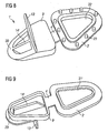
- Figur 9
- eine perspektivische Aufsicht auf den Dosenverschluss aus Figur 8,
- Figur 10
- ein Dosendeckel mit einem erfindungsgemäßen Dosen verschluss in der Transportstellung,
- Figur 11
- eine Unteransicht des Dosendeckels aus Figur 10,
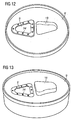
- Figur 12
- eine perspektivische Aufsicht auf den Dosendeckel aus Figur 10 und 11 mit demontiertem Dosenverschluss,
- Figur 13
- eine perspektivische Unteransicht des Dosendeckels aus Figur 12,
- Figur 14
- eine Perspektivansicht eines alternativen Ausführungsbeispiels des erfindungsgemäßen Dosenverschlusses sowie
- Figur 15
- eine Querschnittsansicht des Dosenverschlusses aus Figur 14 im montierten Zustand auf einer Dose.
- Die Figuren 1 bis 5 zeigen einen aus Kunststoff hergestellten Dosenverschluss 1, der im wesentlichen aus einem Verschlussunterteil 2 und einem Verschlussdeckel 3 besteht.
- Das Verschlußunterteil 2 ist über ein Gelenk 4 mit dem Verschlußdeckel 3 verbunden, wobei das Gelenk 4 aus einem Filmscharnier besteht.
- Bei der Montage wird das Verschlussunterteil 2 - wie später erläutert wird - in einem seiner Form angepassten Ausschnitt 5 innerhalb eines Dosendeckels 6 einer Dose 7 befestigt.
- Das Verschlussunterteil 2 weist eine Ausgießöffnung 8 auf, die im Transportzustand der Dose 7 (siehe Fig. 2) mittels einer Abdeckung 9 in Form einer Durchstoßfläche versehen ist. Diese Abdeckung 9 ist in ihren die Ausgießöffnung 8 begrenzenden Bereichen über dünnwandige Sollbruchstellen 10 mit dem Verschlussunterteil 2 verbunden, während ein der Ausgießöffnung 8 gegenüberliegender Bereich der Abdeckung 9 als Filmscharnier 11 gestaltet ist und nach dem Durchstoßen als Gelenk wirkt.
- Der Verschlussdeckel 3 ist ebenfalls mit einer Ausschüttöffnung 12 versehen, die im Gebrauchszustand der Dose 7 mittels einer angelenkten Verschlussklappe 13 wieder verschließbar ist. Im Mittelbereich der Ausschüttöffnung 12 in dem Verschlussdeckel 3 ist eine die Ausschüttöffnung 12 senkrecht übergreifende Durchstoßrippe 14 angeordnet, auf deren Funktion später eingegangen wird.
- Figur 2 zeigt den in den Dosendeckel 6 der Dose 7 integrierten Dosenverschluss 1, wobei die Abdeckung 9 noch mit dem Verschlussunterteil 2 verbunden ist. Wie ferner aus dieser Figur zu ersehen ist, befindet sich in dem Dosendeckel 6 der Ausschnitt 5, in den das Verschlussunterteil 2 mittels eines Spritzvorgangs eingebracht und somit formschlüssig in dem Dosendeckel 6 gehaltert ist. Hierbei besteht die Möglichkeit, an den Innenkonturen des Ausschnittes 5 kleinere Erhebungen bzw. Vertiefungen oder kleine Bohrungen vorzusehen, um eine innige Verbindung zwischen dem Verschlussunterteil 2 und dem Dosendeckel 6 herzustellen.
- Der Dosendeckel 6 besitzt ferner eine den Konturen des Verschlussdeckels 3 angepasste Vertiefung 15, in die der Verschlussdeckel 3 im Transportzustand der Dose 7 eingebracht wird. Dadurch ist es möglich, mehrere Dosen 7 zu Transportzwecken übereinander zu stapeln, ohne dass sich der Verschluss 1 störend auf die Stapelhöhe auswirkt. Die Vertiefung 15 ist deshalb so tief, dass der Verschlussdeckel 3 in der Transportstellung nicht über den Rand der Dose 7 nach oben hinausragt.
- In der in den Figuren 4 und 5 gezeigten Gebrauchsstellung der Dose 7 ist der Verschlussdeckel 3 durch Ziehen an der Durchstoßrippe 14 aus der Vertiefung 15 des Dosendeckels 6 entfernt und in Richtung auf das Verschlussunterteil 2 verschwenkt worden. Bei diesem Vorgang wird mittels der Durchstoßrippe 14, die im Bereich des Gelenks 4 eine Anschrägung 16 (siehe Figur 3) aufweist, die Abdeckung 9 aufgrund ihrer Sollbruchstellen 10 soweit in Richtung Doseninneres gedrückt, bis die Abdeckung 9 an der Anschrägung 16 des Verschlussdeckels 3 zur Anlage gelangt. Die Abdeckung 9 verschwenkt dabei um den Bereich 8 zwischen dem Verschlussunterteil 2 und der Abdeckung 9. In diesem Zustand verrastet der Verschlussdeckel 3 mit dem Verschlussunterteil 2.
- Aus Figur 5 kann ferner ein an dem Verschlussunterteil 2 angeordneter, umlaufender Rastrand 17 ersehen werden, der mit einer an dem Verschlussdeckel 3 angeordneten, ebenfalls umlaufenden Rastaufnahme 18 zusammenwirkt.
- Die Ausschüttöffnung 12 in dem Verschlussdeckel 3 wird mittels der einen Wiederverschluss gestattenden Verschlussklappe 13 abgedeckt. In der in den Figuren 4 und 5 gezeigten Gebrauchslage der Dose 7 kann über die Ausgießöffnung 8 und die Ausschüttöffnung 12 die in der Dose 7 vorhandene Flüssigkeit entnommen werden, wobei durch die Durchstoßrippe 9 die Dosierung der Flüssigkeit beeinflusst werden kann. Nach Beendigung des Ausschüttvorgangs wird die Ausschüttöffnung 12 des Verschlussdeckels 3 mittels der Verschlussklappe 13 abgedeckt. Auch diese Verschlussklappe 13 kann mit dem Verschlussdeckel 3 über ein Filmscharnier 19 schwenkbar verbunden sein und verrastet mit dem Verschlussdeckel 3 im aufgedrückten Zustand.
- Zur angenehmeren Handhabung weist der Verschlussdeckel 3 ferner einen griffartigen Ansatz 20 auf, mit dem der Verschlussdeckel 3 wieder von dem Verschlussunterteil 2 entfernt werden kann.
- Das in den Figuren 6 bis 13 dargestellte Ausführungsbeispiel eines erfindungsgemäßen Dosenverschlusses 1' stimmt weitgehend mit dem vorstehend beschriebenen und in den Figuren 1 bis 5 dargestellten Ausführungsbeispiel überein, so dass im Folgenden zur Vermeidung von Wiederholungen weitgehend auf die vorstehende Beschreibung verwiesen wird und für entsprechende Bauteile dieselben Bezugszeichen verwendet werden, die zur Unterscheidung lediglich durch ein Apostroph gekennzeichnet sind.
- Eine Besonderheit dieses Ausführungsbeispiels besteht darin, das in dem Verschlussunterteil 2' eine schlitzförmige Vertiefung 21' angeordnet ist, die vor der erstmaligen Öffnung an ihrer Unterseite durch eine Abdeckung 22' abgedeckt ist, wobei die Abdekkung 22' durch Soll-Bruchstellen mit dem Verschlussunterteil 2' verbunden ist. Beim Schwenken des Verschlussdeckels 3' von der in den Figuren 6, 8, 9, 10 dargestellten Transportstellung in die in Figur 7 dargestellte Gebrauchsstellung wird die Durchstoßrippe 14' in die schlitzförmige Vertiefung eingeführt und zerbricht dabei die Sollbruchstellen zwischen der Abdeckung 22' an der Unterseite der schlitzförmigen Vertiefung 21' und dem Verschlussunterteil 2', wodurch eine Ausgießöffnung freigegeben wird.
- Darüber hinaus ist aus Figur 8 ersichtlich, das an der Unterseite des Verschlussunterteils 2' kleine Erhebungen 23' angeformt sind, die im montierten Zustand in entsprechende Vertiefungen 24' eingreifen, die in dem Verschlussdeckel 3' im Rand des Ausschnitts 5' für das Verschlussunterteil 2' angebracht sind, wie insbesondere aus den Figuren 13 und 14 ersichtlich ist. Die Erhebungen 23' an dem Verschlussunterteil 2' führen in Verbindung mit den Bohrungen 24' in dem Verschlussdeckel 3' zu einer formschlüssigen Verbindung.
- Das in den Figuren 14 und 15 dargestellte Ausführungsbeispiel eines erfindungsgemäßen Dosenverschlusses 1" stimmt weitgehend mit den vorstehend beschriebenen Ausführungsbeispielen überein, so dass zur Vermeidung von Wiederholungen auf die vorstehende Beschreibung verwiesen wird und im folgenden für entsprechende Bauteile dieselben Bezugszeichen verwendet werden, die lediglich zur Unterscheidung durch zwei Apostrophe gekennzeichnet sind.
- Eine Besonderheit dieses Ausführungsbeispiels besteht darin, dass das Verschlussunterteil 2" aus zwei Kunststoffkomponenten besteht, die eine unterschiedliche Härte aufweist. Die härtere Kunststoffkomponente bildet hierbei eine Dichtung 25", die im montierten Zustand am Rand des Ausschnitts in dem Dosendeckel aufliegt und den Ausschnitt dadurch abdichtet.
- Darüber hinaus verhindert die Dichtung 25" auch eine Korrosion am Rand des Ausschnitts des Dosendeckels, indem die Dichtung 25" den Ausschnittrand umschließt. Dies ist vorteilhaft, da das Ausstanzen des Ausschnitts die Schutzlackschicht auf dem Dosenblech beschädigt und damit korrosionsanfällig macht.
- Die Erfindung ist nicht auf die vorstehend beschriebene bevorzugten Ausführungsbeispiele beschränkt. Vielmehr ist eine Vielzahl von Varianten und Abwandlungen möglich, die ebenfalls von dem erfindungsgemäßen Gedanken Gebrauch machen.
-
- 1, 1', 1"
- Dosenverschluß
- 2, 2', 2"
- Verschlußunterteil
- 3, 3', 3"
- Verschlußdeckel
- 4, 4', 4"
- Gelenk
- 5, 5'
- Ausschnitt
- 6, 6'
- Dosendeckel
- 7, 7', 7"
- Dose
- 8, 8', 8"
- Ausgießöffnung
- 9, 9' 9"
- Abdeckung
- 10, 10'
- Sollbruchstellen
- 11
- Filmscharnier
- 12, 12'
- Ausschüttöffnung
- 13, 13', 13"
- Verschlußklappe
- 14, 14', 14"
- Durchstoßrippe
- 15, 15'
- Vertiefung
- 16, 16'
- Anschrägung der Durchstoßrippe
- 17, 17'
- Rastrand
- 18, 18'
- Rastaufnahme
- 19, 19'
- Filmscharnier
- 20, 20'
- Ansatz
- 21'
- Vertiefung
- 22'
- Abdeckung
- 23'
- Erhebungen
- 24'
- Vertiefungen
- 25 "
- Dichtung
Claims (12)
- Dosenverschluss (1, 1', 1"), insbesondere für eine Milchdose (7, 7"),
wobei der Dosenverschluss (1, 1', 1") in einem Dosendeckel (6, 6') montierbar und werkzeugfrei manuell bedienbar ist,
während der Dosenverschluss (1, 1', 1") mindestens teilweise aus Kunststoff besteht und in einen Ausschnitt (5, 5') in dem Dosendeckel (6, 6') einsetzbar ist,
wobei der Dosenverschluss (1, 1', 1") den Ausschnitt (5, 5') in dem Dosendeckel (6, 6') abdichtet und eine Ausgießöffnung (8, 8', 12, 12') aufweist, mit
einem Verschlußunterteil (2, 2', 2"), das in einen Ausschnitt (5, 5') in dem Dosendeckel (6, 6') einsetzbar ist und mit dem Dosendeckel (6, 6') formschlüssig verbunden werden kann sowie einem Verschlußdeckel (3, 3', 3"), der durch ein Gelenk (4, 4', 4") mit dem Verschlußunterteil (2, 2', 2") verbunden ist und von einer Transportstellung in eine Gebrauchsstellung schwenkbar ist,
wobei die Ausgießöffnung (8, 8', 8") in dem Verschlußunterteil (2, 2', 2") angeordnet ist und der Verschlußdeckel (3, 3', 3") Mittel (14, 14', 14") aufweist, um die in dem Verschlußunterteil (2, 2', 2") angeordnete Ausgießöffnung (8, 8', 8") in der Gebrauchsstellung des Verschlußdeckels (3, 3', 3") zu öffnen,
dadurch gekennzeichnet, dass
in dem Verschlußdeckel (3, 3', 3") eine weitere Ausgießöffnung (12, 12') angeordnet ist, die in der Gebrauchsstellung des Verschlußdeckels (3, 3', 3") über der Ausgießöffnung (8, 8', 8") in dem Verschlußunterteil (2, 2', 2") liegt und durch eine Verschlußklappe (13, 13', 13") wieder verschließbar ist. - Dosenverschluss nach Anspruch 1, dadurch gekennzeichnet, dass die Ausgießöffnung (8, 8', 8", 12, 12') im montierten Zustand zu dem Dosendeckel (6, 6') beabstandet ist.
- Dosenverschluss (1, 1', 1") nach einem der vorhergehenden Ansprüche, dadurch gekennzeichnet, dass die Ausgießöffnung (8, 8', 8") in dem Verschlußunterteil (2, 2', 2 ") in der Transportstellung des Verschlußdeckels (3, 3', 3") vor dem erstmaligen Öffnen durch eine Abdeckung (9, 9', 9") verschlossen ist, die mindestens eine Sollbruchstelle aufweist.
- Dosenverschluss (1, 1', 1") nach einem der vorhergehenden Ansprüche, dadurch gekennzeichnet, dass der Verschlußdeckel (3, 3', 3") als Mittel zum Öffnen der in dem Verschlußunterteil (2, 2', 2") angeordneten Ausgießöffnung (8, 8', 8") eine an der Unterseite des Verschlußdeckels (3, 3', 3") angeordnete Durchstoßrippe (14, 14', 14") aufweist.
- Dosenverschluss (1, 1', 1") nach Anspruch 4, dadurch gekennzeichnet, dass die Durchstoßrippe (14, 14', 14") auf der dem Gelenk (4, 4', 4") zugewandten Seite eine Anschrägung (16, 16') aufweist.
- Dosenverschluss (1, 1', 1") nach einem der vorhergehenden Ansprüche, dadurch gekennzeichnet, dass der Verschlußdeckel (3, 3', 3") einen griffartigen Ansatz (20, 20') aufweist, um den Verschlußdeckel (3, 3', 3") wieder aus der Gebrauchsstellung zu lösen.
- Dosenverschluss (1, 1', 1") nach einem der vorhergehenden Ansprüche, dadurch gekennzeichnet, dass an seiner Unterseite oder an der Unterseite des Verschlußunterteils (2, 2', 2") eine Oberflächenkonturierung (23') vorgesehen ist, um bei einem Kunststoffspritzvorgang eine formschlüssige Verbindung mit einer entsprechenden Oberflächenkonturierung (24') an dem Dosendeckel (6, 6') zu bilden.
- Dosenverschluss (1, 1', 1") nach einem der vorhergehenden Ansprüche, dadurch gekennzeichnet, dass das Verschlußunterteil (2, 2', 2") und der Verschlußdeckel (3, 3', 3") Rastelemente (17, 17', 18, 18') aufweisen, um in der Gebrauchsstellung des Verschlußdeckels (3, 3', 3") eine Rastverbindung zwischen dem Verschlußunterteil (2, 2', 2") und dem Verschlußdeckel (3, 3', 3 ") zu bilden.
- Dosenverschluss (1, 1', 1") nach einem der vorhergehenden Ansprüche, dadurch gekennzeichnet, dass zur Verbindung mit dem Dosendeckel (6, 6') eine Ultraschallverschweißung vorgesehen ist.
- Dosenverschluss (1, 1', 1") nach einem der vorhergehenden Ansprüche, dadurch gekennzeichnet, dass das Verschlussunterteil (2, 2', 2") aus einer härteren und einer weicheren Komponente besteht, wobei die weichere Komponente im montierten Zustand als Dichtung (25") an dem Rand des Ausschnitts (5, 5') in dem Dosendeckel (6, 6') anliegt.
- Dosenverschluss (1, 1' , 1") nach Anspruch 10, dadurch gekennzeichnet, dass die weichere Komponente (25") des Verschlussunterteils (2, 2', 2") im montierten Zustand den Rand des Ausschnitts (5, 5') in dem Dosendeckel (6, 6') umschließt.
- Dose (7, 7', 7"), inbesondere Milchdose, mit einem Dosenverschluss (1, 1', 1") nach einem der Ansprüche 1 bis 11.
Applications Claiming Priority (5)
| Application Number | Priority Date | Filing Date | Title |
|---|---|---|---|
| DE10244349 | 2002-09-24 | ||
| DE10244349A DE10244349A1 (de) | 2002-09-24 | 2002-09-24 | Verschluss für ausgießbare Flüssigkeiten enthaltene Dosen |
| DE10312237 | 2003-03-19 | ||
| DE10312237A DE10312237A1 (de) | 2002-03-19 | 2003-03-19 | Dosenverschluß, Dosendeckel und Dose |
| PCT/EP2003/010640 WO2004028917A2 (de) | 2002-09-24 | 2003-09-24 | Dosenverschluss, dosendeckel und dose |
Publications (2)
| Publication Number | Publication Date |
|---|---|
| EP1542909A2 EP1542909A2 (de) | 2005-06-22 |
| EP1542909B1 true EP1542909B1 (de) | 2006-05-17 |
Family
ID=32043958
Family Applications (1)
| Application Number | Title | Priority Date | Filing Date |
|---|---|---|---|
| EP03753451A Expired - Lifetime EP1542909B1 (de) | 2002-09-24 | 2003-09-24 | Dosenverschluss, dosendeckel und dose |
Country Status (7)
| Country | Link |
|---|---|
| EP (1) | EP1542909B1 (de) |
| AT (1) | ATE326395T1 (de) |
| AU (1) | AU2003271638A1 (de) |
| CA (1) | CA2502866C (de) |
| DE (1) | DE50303385D1 (de) |
| MX (1) | MXPA05003312A (de) |
| WO (1) | WO2004028917A2 (de) |
Cited By (1)
| Publication number | Priority date | Publication date | Assignee | Title |
|---|---|---|---|---|
| DE102013003154B3 (de) * | 2013-02-25 | 2014-01-16 | Euro-Cap Gmbh | Dosenverschluss |
Families Citing this family (2)
| Publication number | Priority date | Publication date | Assignee | Title |
|---|---|---|---|---|
| DE102006054788A1 (de) * | 2006-11-21 | 2008-05-29 | Sooth, Jürgen | Montageverfahren und Montagevorrichtung zur Montage eines Dosenverschlusses in einer Metalldose |
| DE202011101705U1 (de) | 2011-06-10 | 2011-09-12 | Euro-Cap Gmbh | Verschluss für einen Flüssigkeitsbehälter, insbesondere für eine Getränkedose |
Family Cites Families (7)
| Publication number | Priority date | Publication date | Assignee | Title |
|---|---|---|---|---|
| US2885084A (en) * | 1957-09-03 | 1959-05-05 | Rocca John | Filter means for milk containers and the like |
| SE9200391L (sv) * | 1992-02-11 | 1993-08-12 | Tetra Laval Holdings & Finance | Öppningsanordning |
| DE69207895T2 (de) * | 1992-07-06 | 1996-09-05 | Procter & Gamble | Aseptische Flüssigkeitsverpackung versehen mit einem wiederverschliessbaren Öffnungselement |
| US5806757A (en) * | 1994-06-02 | 1998-09-15 | Tetra Laval Holdings & Finance S.A. | Device for unsealing pour opening of liquid container |
| DE9420437U1 (de) * | 1994-12-21 | 1995-02-16 | Hornig, Wolfgang, Dr., 69245 Bammental | Aufsatz |
| EP1038784B1 (de) * | 1999-03-25 | 2003-05-28 | Guglielmo Ferrari | Zu öffnende Giessvorrichtung für Lebensmittelbehälter |
| DE10017467A1 (de) * | 2000-03-08 | 2001-09-13 | Elvira Ahrens | Ausgießer für Europaks |
-
2003
- 2003-09-24 DE DE50303385T patent/DE50303385D1/de not_active Expired - Lifetime
- 2003-09-24 AU AU2003271638A patent/AU2003271638A1/en not_active Abandoned
- 2003-09-24 CA CA002502866A patent/CA2502866C/en not_active Expired - Fee Related
- 2003-09-24 MX MXPA05003312A patent/MXPA05003312A/es active IP Right Grant
- 2003-09-24 EP EP03753451A patent/EP1542909B1/de not_active Expired - Lifetime
- 2003-09-24 AT AT03753451T patent/ATE326395T1/de not_active IP Right Cessation
- 2003-09-24 WO PCT/EP2003/010640 patent/WO2004028917A2/de not_active Ceased
Cited By (2)
| Publication number | Priority date | Publication date | Assignee | Title |
|---|---|---|---|---|
| DE102013003154B3 (de) * | 2013-02-25 | 2014-01-16 | Euro-Cap Gmbh | Dosenverschluss |
| WO2014127887A1 (de) | 2013-02-25 | 2014-08-28 | Euro-Cap Gmbh | Dosenverschluss mit innenliegendem verschlussteil |
Also Published As
| Publication number | Publication date |
|---|---|
| WO2004028917A2 (de) | 2004-04-08 |
| DE50303385D1 (de) | 2006-06-22 |
| ATE326395T1 (de) | 2006-06-15 |
| MXPA05003312A (es) | 2005-10-18 |
| CA2502866A1 (en) | 2004-04-08 |
| AU2003271638A1 (en) | 2004-04-19 |
| CA2502866C (en) | 2009-11-24 |
| EP1542909A2 (de) | 2005-06-22 |
| WO2004028917A3 (de) | 2004-10-28 |
| AU2003271638A8 (en) | 2004-04-19 |
Similar Documents
| Publication | Publication Date | Title |
|---|---|---|
| DE3840251C2 (de) | Getränkebehälterverschluß | |
| DE60031392T2 (de) | Behälterverschluss | |
| AT394346B (de) | Zweiteiliger garantieverschluss | |
| EP1812298A1 (de) | Flacher selbstöffner-verschluss für verbundpackungen oder für mit folienmaterial zu verschliessende behälter- oder flaschenstutzen | |
| CH692194A5 (de) | Verpackung. | |
| WO2008049420A1 (de) | Verpackung mit einem verschlussbereich | |
| EP0883550B1 (de) | Vorrichtung zum öffnen und wiederverschliessen von behältern | |
| DE4410790A1 (de) | Schraubkappe mit Anschweißring | |
| DE102006035761A1 (de) | Verschlusskappe für einen mit einer medizinischen Flüssigkeit befüllten Behälter und Behälter mit einer Verschlusskappe | |
| DE20118537U1 (de) | Klappverschluß | |
| DE69903815T2 (de) | Verschluss mit perforierungs-mitteln und ausgiessdüse | |
| DE69222866T2 (de) | Kindersicherer verschluss mit schutzrand und geneigter oberen wand | |
| DE2428395A1 (de) | Leicht zu oeffnender behaelter | |
| EP1542909B1 (de) | Dosenverschluss, dosendeckel und dose | |
| DE8228681U1 (de) | Blechdeckel fuer eine Dose fuer fluessiges Fuellgut | |
| WO2001046032A2 (de) | Klappdeckelverschluss mit originalitätssicherung | |
| DE3201469A1 (de) | Wiederverschliessbarer metalldeckel fuer eine dose fuer fluessige fuellgueter | |
| EP1973798A1 (de) | Behälterverschluss | |
| DE10312237A1 (de) | Dosenverschluß, Dosendeckel und Dose | |
| DE4219571A1 (de) | Vorrichtung zur Entnahme einer Flüssigkeit aus einem Behälter, insbesondere einem 10 bzw. 5-Liter-Party-Bierfaß | |
| DE102011101609A1 (de) | Wiederverschließbarer Behälter / Getränkedose | |
| EP3652083B1 (de) | Behälterverschluss mit einer standardkapsel | |
| DE10244349A1 (de) | Verschluss für ausgießbare Flüssigkeiten enthaltene Dosen | |
| WO2021043720A1 (de) | Behälterverschluss | |
| DE19711578C2 (de) | Vorrichtung zum Öffnen und Wiederverschließen von Behältern |
Legal Events
| Date | Code | Title | Description |
|---|---|---|---|
| PUAI | Public reference made under article 153(3) epc to a published international application that has entered the european phase |
Free format text: ORIGINAL CODE: 0009012 |
|
| 17P | Request for examination filed |
Effective date: 20050419 |
|
| AK | Designated contracting states |
Kind code of ref document: A2 Designated state(s): AT BE BG CH CY CZ DE DK EE ES FI FR GB GR HU IE IT LI LU MC NL PT RO SE SI SK TR |
|
| AX | Request for extension of the european patent |
Extension state: AL LT LV MK |
|
| GRAP | Despatch of communication of intention to grant a patent |
Free format text: ORIGINAL CODE: EPIDOSNIGR1 |
|
| DAX | Request for extension of the european patent (deleted) | ||
| GRAS | Grant fee paid |
Free format text: ORIGINAL CODE: EPIDOSNIGR3 |
|
| GRAA | (expected) grant |
Free format text: ORIGINAL CODE: 0009210 |
|
| AK | Designated contracting states |
Kind code of ref document: B1 Designated state(s): AT BE BG CH CY CZ DE DK EE ES FI FR GB GR HU IE IT LI LU MC NL PT RO SE SI SK TR |
|
| PG25 | Lapsed in a contracting state [announced via postgrant information from national office to epo] |
Ref country code: RO Free format text: LAPSE BECAUSE OF FAILURE TO SUBMIT A TRANSLATION OF THE DESCRIPTION OR TO PAY THE FEE WITHIN THE PRESCRIBED TIME-LIMIT Effective date: 20060517 Ref country code: SK Free format text: LAPSE BECAUSE OF FAILURE TO SUBMIT A TRANSLATION OF THE DESCRIPTION OR TO PAY THE FEE WITHIN THE PRESCRIBED TIME-LIMIT Effective date: 20060517 Ref country code: SI Free format text: LAPSE BECAUSE OF FAILURE TO SUBMIT A TRANSLATION OF THE DESCRIPTION OR TO PAY THE FEE WITHIN THE PRESCRIBED TIME-LIMIT Effective date: 20060517 Ref country code: CZ Free format text: LAPSE BECAUSE OF FAILURE TO SUBMIT A TRANSLATION OF THE DESCRIPTION OR TO PAY THE FEE WITHIN THE PRESCRIBED TIME-LIMIT Effective date: 20060517 Ref country code: IE Free format text: LAPSE BECAUSE OF FAILURE TO SUBMIT A TRANSLATION OF THE DESCRIPTION OR TO PAY THE FEE WITHIN THE PRESCRIBED TIME-LIMIT Effective date: 20060517 Ref country code: FI Free format text: LAPSE BECAUSE OF FAILURE TO SUBMIT A TRANSLATION OF THE DESCRIPTION OR TO PAY THE FEE WITHIN THE PRESCRIBED TIME-LIMIT Effective date: 20060517 Ref country code: IT Free format text: LAPSE BECAUSE OF FAILURE TO SUBMIT A TRANSLATION OF THE DESCRIPTION OR TO PAY THE FEE WITHIN THE PRESCRIBED TIME-LIMIT;WARNING: LAPSES OF ITALIAN PATENTS WITH EFFECTIVE DATE BEFORE 2007 MAY HAVE OCCURRED AT ANY TIME BEFORE 2007. THE CORRECT EFFECTIVE DATE MAY BE DIFFERENT FROM THE ONE RECORDED. Effective date: 20060517 |
|
| REG | Reference to a national code |
Ref country code: GB Ref legal event code: FG4D Free format text: NOT ENGLISH |
|
| REG | Reference to a national code |
Ref country code: CH Ref legal event code: EP |
|
| REG | Reference to a national code |
Ref country code: IE Ref legal event code: FG4D Free format text: LANGUAGE OF EP DOCUMENT: GERMAN |
|
| REF | Corresponds to: |
Ref document number: 50303385 Country of ref document: DE Date of ref document: 20060622 Kind code of ref document: P |
|
| PG25 | Lapsed in a contracting state [announced via postgrant information from national office to epo] |
Ref country code: DK Free format text: LAPSE BECAUSE OF FAILURE TO SUBMIT A TRANSLATION OF THE DESCRIPTION OR TO PAY THE FEE WITHIN THE PRESCRIBED TIME-LIMIT Effective date: 20060817 Ref country code: SE Free format text: LAPSE BECAUSE OF FAILURE TO SUBMIT A TRANSLATION OF THE DESCRIPTION OR TO PAY THE FEE WITHIN THE PRESCRIBED TIME-LIMIT Effective date: 20060817 |
|
| PG25 | Lapsed in a contracting state [announced via postgrant information from national office to epo] |
Ref country code: ES Free format text: LAPSE BECAUSE OF FAILURE TO SUBMIT A TRANSLATION OF THE DESCRIPTION OR TO PAY THE FEE WITHIN THE PRESCRIBED TIME-LIMIT Effective date: 20060828 |
|
| PG25 | Lapsed in a contracting state [announced via postgrant information from national office to epo] |
Ref country code: BE Free format text: LAPSE BECAUSE OF NON-PAYMENT OF DUE FEES Effective date: 20060930 Ref country code: MC Free format text: LAPSE BECAUSE OF NON-PAYMENT OF DUE FEES Effective date: 20060930 |
|
| GBT | Gb: translation of ep patent filed (gb section 77(6)(a)/1977) |
Effective date: 20060911 |
|
| REG | Reference to a national code |
Ref country code: GR Ref legal event code: EP Ref document number: 20060402832 Country of ref document: GR |
|
| PG25 | Lapsed in a contracting state [announced via postgrant information from national office to epo] |
Ref country code: PT Free format text: LAPSE BECAUSE OF FAILURE TO SUBMIT A TRANSLATION OF THE DESCRIPTION OR TO PAY THE FEE WITHIN THE PRESCRIBED TIME-LIMIT Effective date: 20061017 |
|
| REG | Reference to a national code |
Ref country code: IE Ref legal event code: FD4D |
|
| ET | Fr: translation filed | ||
| PLBE | No opposition filed within time limit |
Free format text: ORIGINAL CODE: 0009261 |
|
| STAA | Information on the status of an ep patent application or granted ep patent |
Free format text: STATUS: NO OPPOSITION FILED WITHIN TIME LIMIT |
|
| 26N | No opposition filed |
Effective date: 20070220 |
|
| PG25 | Lapsed in a contracting state [announced via postgrant information from national office to epo] |
Ref country code: AT Free format text: LAPSE BECAUSE OF NON-PAYMENT OF DUE FEES Effective date: 20060924 |
|
| BERE | Be: lapsed |
Owner name: SOOTH, JURGEN Effective date: 20060930 |
|
| REG | Reference to a national code |
Ref country code: CH Ref legal event code: PL |
|
| PG25 | Lapsed in a contracting state [announced via postgrant information from national office to epo] |
Ref country code: EE Free format text: LAPSE BECAUSE OF FAILURE TO SUBMIT A TRANSLATION OF THE DESCRIPTION OR TO PAY THE FEE WITHIN THE PRESCRIBED TIME-LIMIT Effective date: 20060517 Ref country code: BG Free format text: LAPSE BECAUSE OF FAILURE TO SUBMIT A TRANSLATION OF THE DESCRIPTION OR TO PAY THE FEE WITHIN THE PRESCRIBED TIME-LIMIT Effective date: 20060817 |
|
| PG25 | Lapsed in a contracting state [announced via postgrant information from national office to epo] |
Ref country code: HU Free format text: LAPSE BECAUSE OF FAILURE TO SUBMIT A TRANSLATION OF THE DESCRIPTION OR TO PAY THE FEE WITHIN THE PRESCRIBED TIME-LIMIT Effective date: 20061118 Ref country code: LI Free format text: LAPSE BECAUSE OF NON-PAYMENT OF DUE FEES Effective date: 20070930 Ref country code: TR Free format text: LAPSE BECAUSE OF FAILURE TO SUBMIT A TRANSLATION OF THE DESCRIPTION OR TO PAY THE FEE WITHIN THE PRESCRIBED TIME-LIMIT Effective date: 20060517 Ref country code: CH Free format text: LAPSE BECAUSE OF NON-PAYMENT OF DUE FEES Effective date: 20070930 Ref country code: LU Free format text: LAPSE BECAUSE OF NON-PAYMENT OF DUE FEES Effective date: 20060924 |
|
| PG25 | Lapsed in a contracting state [announced via postgrant information from national office to epo] |
Ref country code: CY Free format text: LAPSE BECAUSE OF FAILURE TO SUBMIT A TRANSLATION OF THE DESCRIPTION OR TO PAY THE FEE WITHIN THE PRESCRIBED TIME-LIMIT Effective date: 20060517 |
|
| REG | Reference to a national code |
Ref country code: FR Ref legal event code: PLFP Year of fee payment: 14 |
|
| REG | Reference to a national code |
Ref country code: FR Ref legal event code: PLFP Year of fee payment: 15 |
|
| REG | Reference to a national code |
Ref country code: FR Ref legal event code: PLFP Year of fee payment: 16 |
|
| PGFP | Annual fee paid to national office [announced via postgrant information from national office to epo] |
Ref country code: FR Payment date: 20180921 Year of fee payment: 16 |
|
| PGFP | Annual fee paid to national office [announced via postgrant information from national office to epo] |
Ref country code: GB Payment date: 20180924 Year of fee payment: 16 |
|
| PGFP | Annual fee paid to national office [announced via postgrant information from national office to epo] |
Ref country code: NL Payment date: 20190923 Year of fee payment: 17 |
|
| PGFP | Annual fee paid to national office [announced via postgrant information from national office to epo] |
Ref country code: GR Payment date: 20190919 Year of fee payment: 17 |
|
| PGFP | Annual fee paid to national office [announced via postgrant information from national office to epo] |
Ref country code: DE Payment date: 20191106 Year of fee payment: 17 |
|
| GBPC | Gb: european patent ceased through non-payment of renewal fee |
Effective date: 20190924 |
|
| PG25 | Lapsed in a contracting state [announced via postgrant information from national office to epo] |
Ref country code: FR Free format text: LAPSE BECAUSE OF NON-PAYMENT OF DUE FEES Effective date: 20190930 Ref country code: GB Free format text: LAPSE BECAUSE OF NON-PAYMENT OF DUE FEES Effective date: 20190924 |
|
| REG | Reference to a national code |
Ref country code: DE Ref legal event code: R119 Ref document number: 50303385 Country of ref document: DE |
|
| REG | Reference to a national code |
Ref country code: NL Ref legal event code: MM Effective date: 20201001 |
|
| PG25 | Lapsed in a contracting state [announced via postgrant information from national office to epo] |
Ref country code: NL Free format text: LAPSE BECAUSE OF NON-PAYMENT OF DUE FEES Effective date: 20201001 |
|
| PG25 | Lapsed in a contracting state [announced via postgrant information from national office to epo] |
Ref country code: DE Free format text: LAPSE BECAUSE OF NON-PAYMENT OF DUE FEES Effective date: 20210401 Ref country code: GR Free format text: LAPSE BECAUSE OF NON-PAYMENT OF DUE FEES Effective date: 20210406 |