EP1541466A2 - Verfahren und Vorrichtung für den schnellen Aus- und Einbau von Flugzeugsitzen - Google Patents
Verfahren und Vorrichtung für den schnellen Aus- und Einbau von Flugzeugsitzen Download PDFInfo
- Publication number
- EP1541466A2 EP1541466A2 EP04106257A EP04106257A EP1541466A2 EP 1541466 A2 EP1541466 A2 EP 1541466A2 EP 04106257 A EP04106257 A EP 04106257A EP 04106257 A EP04106257 A EP 04106257A EP 1541466 A2 EP1541466 A2 EP 1541466A2
- Authority
- EP
- European Patent Office
- Prior art keywords
- seats
- bottom plate
- chassis
- transport
- horizontal
- Prior art date
- Legal status (The legal status is an assumption and is not a legal conclusion. Google has not performed a legal analysis and makes no representation as to the accuracy of the status listed.)
- Granted
Links
Images




Classifications
-
- B—PERFORMING OPERATIONS; TRANSPORTING
- B64—AIRCRAFT; AVIATION; COSMONAUTICS
- B64D—EQUIPMENT FOR FITTING IN OR TO AIRCRAFT; FLIGHT SUITS; PARACHUTES; ARRANGEMENT OR MOUNTING OF POWER PLANTS OR PROPULSION TRANSMISSIONS IN AIRCRAFT
- B64D11/00—Passenger or crew accommodation; Flight-deck installations not otherwise provided for
- B64D11/06—Arrangements of seats, or adaptations or details specially adapted for aircraft seats
- B64D11/0696—Means for fastening seats to floors, e.g. to floor rails
-
- B—PERFORMING OPERATIONS; TRANSPORTING
- B64—AIRCRAFT; AVIATION; COSMONAUTICS
- B64F—GROUND OR AIRCRAFT-CARRIER-DECK INSTALLATIONS SPECIALLY ADAPTED FOR USE IN CONNECTION WITH AIRCRAFT; DESIGNING, MANUFACTURING, ASSEMBLING, CLEANING, MAINTAINING OR REPAIRING AIRCRAFT, NOT OTHERWISE PROVIDED FOR; HANDLING, TRANSPORTING, TESTING OR INSPECTING AIRCRAFT COMPONENTS, NOT OTHERWISE PROVIDED FOR
- B64F5/00—Designing, manufacturing, assembling, cleaning, maintaining or repairing aircraft, not otherwise provided for; Handling, transporting, testing or inspecting aircraft components, not otherwise provided for
- B64F5/50—Handling or transporting aircraft components
Definitions
- the present invention relates to a method and apparatus for installing and removing seats in passenger aircraft, wherein the device comprises a wheeled chassis, which represents a mobile transport device, with which the seats, specifically passenger seats of a Airplane, can be transported out of the plane and transported back into it.
- a wheeled chassis which represents a mobile transport device, with which the seats, specifically passenger seats of a Airplane, can be transported out of the plane and transported back into it.
- Corresponding methods and devices have long been known in the art, wherein these methods and devices are based essentially on the manual assembly of the aircraft seats, i.e. the loosening and fastening of the seats from the ground and the taking over or lifting of the Seats on a low-built trolley or the like, the seats then, standing on the transport cart, out of the plane and also transported back into it can be.
- the present invention is therefore based on the object, a method and an apparatus for the removal and installation of the seats in a passenger plane, which the Aus- and Installation process greatly facilitated and accelerated and even with relatively large, sweeping and allows heavy sitting in a relatively simple manner and a short time.
- the object underlying the invention is characterized solved that to remove the seats, the transport device in the space between two successively arranged rows of seats moves and with the bottom plate of the seats in engagement is brought, the seat backs are folded back as far as possible and the bottom plate lifted with one or more of the seats mounted on the bottom plate and removed from the horizontal Position is tilted out, whereupon the transport device with the over the bottom plate seats held out of the rows of seats and through the passage between the rows of seats is driven while installing the above steps substantially in reverse Order to be gone through.
- the order of steps it should be noted that for expansion, of course, first the transport device in the space between two consecutive rows of seats must be retracted and the holding device with the Bottom plate must be engaged. However, this can happen both before and after folding back Seat backs take place in a shallower position.
- the seat backs in a completely flat or aligned with the seat portion lying position brought.
- any easily detachable panels that surround the seats as a whole or between the seats located armrests and control panels, for example, controls for the Adjustment of the seat back, folding tables, phono / video connections, etc. included, to be dismantled, as these elements are usually of the actual, fixed to the bottom plate mounted seats are easily removable.
- this results in an advantageous manner between two adjacent Often there is a gap of at least 10 cm, often 20 cm wide, in which a holding device swung in a simple manner and brought into engagement with the bottom plate can.
- a holding device for the bottom plate of the seats inclined from one to the horizontal and preferably pivoted in a substantially horizontal position in a horizontal position to the To pick up the bottom plate of the seats or to settle this bottom plate on the floor during installation.
- bottom plate is to be understood very generally is and not just ideal plate-shaped elements includes, but in general the part of Underframes of aircraft seats, which are firmly locked in the ground with appropriate brackets or firmly screwed.
- the holding device preferably engages in a gap between two side by side arranged seats, it being understood that the width of the holding device less than the width of a corresponding gap, which is between two seats forms when interposed armrests and / or control panels are removed. It would be However, in principle also conceivable that in seats in which such a gap between adjacent Sitting does not arise, the holding device pushed under the seat and with the bottom plate is engaged.
- the bottom plate for transporting the Seats are aligned in a substantially vertical direction, in other words, the bottom plate is pivoted, starting from its arrangement on the ground, by substantially 90 °. If at This method also bring the backs of the seats in a full reclining position, means this that both the seat and the backrest substantially parallel to the Aligned bottom plate and thus after the erection of the bottom plate also substantially are vertically aligned. In this way one achieves a relatively narrow transport profile of the seats, if they are then transported one side forward through the row of seats of an aircraft.
- the device further comprises a support device designed for the expansion of seats to be brought into engagement with the bottom plate of the seat of a row of seats and to hold the bottom plate and which can be brought into a position for the transport of the seats, in which the base plate is inclined relative to the horizontal, preferably vertically aligned.
- the chassis has an oblong rectangular frame and a corresponding shaped plate on which or on which a mounting device is mounted, which in essentially inclined from one at least during transport and driving to the horizontal Alignable shank, which for receiving and laying down a bottom plate in a is movable substantially horizontal, transversely over the bottom plate extending position.
- Bottom plate extends) pointing in the direction of the bottom plate facing claws, of which at least one is slidable along the shaft relative to the other so as to be between the jaws pinch and hold the bottom plate of the seats.
- the claws are suitably designed so that they with a front or a back edge of the bottom plate are engageable, again taking into account that the "bottom plate” can also be a not necessarily exactly plate-shaped base frame, which but in any case any front edge or front edge and a rear edge or a rear edge (as seen in the normal sitting direction), so that these edges of two Claws detected and the "bottom plate” can be clamped between the jaws.
- the stem and the claws disposed thereon preferably have a width, which, in the event that seats are to be taken, between which a corresponding gap is present, have a width which is less than this gap width.
- this is Width of the holding device and the claws less than 25 cm, preferably less than 20 cm, but more than 5 cm
- the shaft is substantially between one vertically aligned and a substantially horizontally oriented position pivotable arranged on the chassis.
- the shaft is rigid on the chassis or a plate or a frame of the chassis mounted and in the driving position substantially is vertically aligned and is for gripping or removing the bottom plate together with the entire chassis tiltable.
- the shaft is close to or substantially above this Longitudinal edge of the chassis or frame or the plate is arranged and runs during the transport substantially perpendicular or slightly offset over the defined by the boom Tilting axle and near one of the longitudinal edges of the chassis.
- a lever mechanism is expediently provided, whose positions correspond to two end positions of the holding device, wherein an end position the open position of the holding device corresponds, in which the holding device with the bottom plate the seats is disengaged and the other end position defines a position in which the Retaining device is in firm engagement with the bottom plate of the seats.
- FIG 1 schematically in a side view of an aircraft seat 1, consisting of a floor panel 5 lockable with support members fixedly attached to the floor of the aircraft is a seat part 4, a perenniallehne2 and an armrest 3.
- a seat part 4 a perennially movable seat
- a vicious circle2 a vicious circle
- an armrest 3 a styrene-like seat
- the seat shown here in its concrete form is shown only roughly schematically and that Of course, the backrest can be slightly inclined and also the seat is not the one shown, has exactly rectangular shape.
- the bottom plate does not have to be a flat, flat plate, but rather may also be a somehow structured frame or profiled perforated plate or the like.
- FIG. 2 schematically shows the same seat 1, but in a position in which the backrest 2 folded flat into a reclining position.
- a reclining position is at least in some Sitting the higher category adjustable, but just these seats also larger overall Dimensions have, so that their transport through the rows of seats of aircraft in general difficult.
- two such seats are arranged directly next to each other and they can also have a two seats enclosing, outer lining, but easily removable and is transportable separately.
- two such seats is generally one slightly wider (for example, up to 20 cm wide) double armrest arranged, which also has a Series of controls for the seat and possibly also a folding table or the like contains.
- this backrest between two seats can be easily disassembled and is for removing the seats so that a gap is created between the two adjacent seats, in which a suitably designed transport device can intervene with the Bottom plate of the seats to engage.
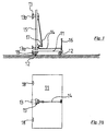
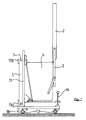
- Figure 3 shows a corresponding transport device in the form of a small cart with a Base plate 11, at the bottom of which four steering rollers 12 are mounted, of which here only two are visible, as in the plan view of the figure of the rectangular elongated transport carts here only from its narrow side is visible.
- a shaft 15 is mounted, which is aligned substantially perpendicular to the base plate 11 and fixed is mounted on this base plate.
- a tensioning device 13 in Form of two claws 13 a, 13 b mounted, in which case the claw 13 a fixed to the shaft 15th is mounted while the claw 13b via a linkage 14 on the shaft 15 vertically displaceable is so that the distance between the claws 13a, 13b can be changed.
- This change in distance takes place by means of a lever and joint mechanism with the articulated lever 16 and a Lever 17, wherein the linkage or lever mechanism is formed so that it is between the two end positions of the claws 13a, 13b passes over a dead center and so at least the Clamping position is a stable, not self-releasing position.
- FIG. 4 The illustration in Figure 4 is merely schematic and does not show the actual training of Linkage and lever mechanism. It also recognizes a boom 18, which at the Longitudinal edge of the base plate 11 is mounted, in fact, two such cantilevers on this Longitudinal edge of the base plate 11 are attached, as shown in a schematic plan view according to Figure 3a recognizes. In the plan view of Figure 3a can be seen from above on the base plate 11 and one also recognizes the shaft 15 with the upper jaw 13b mounted thereon from above.
- Figure 4 shows again the transport device according to Figure 3, but in this case in a different position of the lever 16, which is defined as the open position, since in this position the upper jaw 13b has a greater distance from the claw 13a than in the holding position shown in Figure 3.
- Figure 5 one recognizes the transport device in front of a row of seats, wherein in Figure 5a, the position of the trolley 10 in front of the seats 1 is again shown in a view from above.
- two seats 1 are arranged side by side, with a Gap S between, which is wider than the corresponding width of the shaft 15 and the claws 13th the transport device.
- the seats 1 are mounted on the bottom plate 5 and their backs 2 are folded down into a lying position.
- the armrests 3 are attached to the backrests 2, that they are also lowered when folding back the backrests and with their Upper edge about reach the level of seat height.
- Figure 5 is indicated by a double arrow that the transport device tilted accordingly can be, with the lifting of the transport device on the right side of the left Edge lowers, so that the boom 18 come into contact with the ground and then a Define tilt axis for the entire device.
- FIG. 6 shows the transport device 10 in the completely overturned position.
- the shaft 15 is located across the bottom plate 5, the two jaws 13a, 13b are with the front and rear Edge 6, 7 of the plate 5 in engagement after the lever 16 has been brought into the clamping position.
- the lever is folded in the position shown in Figure 5.
- the backrests 2 can now be easily detected and raised be, with the entire transport device 10 together with the entire seat 1 again is erected in the normal driving position, again with the two arms 18 as a tilting bearing serve.
- the particular advantage of this is that, first, the seat in this Form has a particularly narrow profile, which is significantly lower than it otherwise the depth of the seat in the position shown for example in Figure 1 corresponds, so also the width of the trolley 10 does not exceed.
- the other special advantage is that the seat is not with any sensitive trim or upholstery parts gets up on the trolley because otherwise these delicate parts could be damaged or soiled, especially as the whole Seat together with the base frame and the bottom plate 5 often a considerable weight in the May have order of magnitude of 80 to 100 kg.
- the bottom plate 5 is together with the corresponding Underframe but generally designed to the weight of the entire row of seats in the To transfer aircraft fuselage and therefore can be on the bottom plate 5 and the weight of the entire seat can be worn easily and is about the claws and the shaft 15 on the Transport device or its base plate 11 and the wheels 12 removed.
- the shaft 15 is not aligned perpendicular to the base plate 11, but extends in one inclined position and in particular it can also be pivotable relative to the base plate, to set an optimal position.
- the horizontal position i.e. the distance of the shaft 15 to the edge 19 of the base plate 11 and a corresponding one Chassis variable adjustable, expediently then also the entire lever and Linkage mechanism together with the shank on the chassis or the base plate 11 is displaceable.
- FIG. 7 shows the erected transport device together with it alone Seat 1 held above the base plate 1. It is particularly evident in this position narrow transport profile, which is the width of the tuned to the aisle width of an aircraft Transport device 10 does not exceed.
Landscapes
- Engineering & Computer Science (AREA)
- Transportation (AREA)
- Aviation & Aerospace Engineering (AREA)
- Manufacturing & Machinery (AREA)
- Handcart (AREA)
- Automobile Manufacture Line, Endless Track Vehicle, Trailer (AREA)
Abstract
Description
- Figur 1
- zeigt schematisch einen Flugzeugsitz in einer Sitzposition mit aufgerichteter Rückenlehne,
- Figur 2
- zeigt den Sitz nach Figur 1, jedoch mit einer in Liegeposition zurückgeklappten Rückenlehne,
- Figur 3
- zeigt eine erfindungsgemäße Transportvorrichtung in einer Halteposition,
- Figur 4
- zeigt die Haltevorrichtung aus Figur 3, jedoch in einer offenen Position,
- Figur 5
- zeigt eine Seitenansicht einer vor einem bzw. zwei Sitzen angeordnete Transportvorrichtung,
- Figur 6
- zeigt die Transportvorrichtung in umgeklapptem Zustand in einer Position zwischen zwei benachbarten Sitzen und
- Figur 7
- zeigt die Transportvorrichtung mit dem daran gehaltenen Sitz in einer Transportposition.
Claims (15)
- Verfahren zum Ein- und Ausbau von Sitzen in einem Passagierflugzeug mit Hilfe einer auf Rädern fahrenden Transporteinrichtung, dadurch gekennzeichnet, daß zum Ausbau der Sitze die Transporteinrichtung in den Zwischenraum zwischen zwei hintereinander angeordnete Sitzreihen hineinbewegt und mit der Bodenplatte einer Sitzreihe in Eingriff gebracht wird, die Sitzlehnen so weit wie möglich nach hinten geklappt werden und die Bodenplatte mit einem oder mehreren an der Bodenplatte montierten Sitzen angehoben und in eine gegenüber der Horizontalen geneigte Position gekippt wird, woraufhin die Transporteinrichtung mit den über die Bodenplatte daran gehaltenen Sitzen aus der Sitzreihe heraus und durch den Gang zwischen den Sitzreihen gefahren werden, während zum Einbau die vorstehend beschriebenen Schritte im wesentlichen in umgekehrter Reihenfolge durchlaufen werden.
- Verfahren nach Anspruch 1, dadurch gekennzeichnet, daß eine Haltevorrichtung für die Bodenplatte der Sitze aus einer gegenüber der Horizontalen geneigten und vorzugsweise im wesentlichen vertikalen Position zum Aufnehmen bzw. Absetzen der Bodenplatte der Sitze in eine im wesentlichen horizontale Position verschwenkt wird.
- Verfahren nach Anspruch 1 oder 2, dadurch gekennzeichnet, daß zum Halten der Bodenplatte je eine vordere und eine hintere Kante der Bodenplatte von gegenüberliegenden Klauen einer Halteeinrichtung ergriffen werden.
- Verfahren nach einem der Ansprüche 1 bis 3, dadurch gekennzeichnet, daß die Halteeinrichtung in einen Spalt zwischen zwei nebeneinander angeordneten Sitzen hindurchbewegt wird, um mit der Bodenplatte in- und außer Eingriff zu treten.
- Verfahren nach einem der Ansprüche 1 bis 4, dadurch gekennzeichnet, daß die Bodenplatte zum Transport der Sitze im wesentlichen vertikal ausgerichtet wird.
- Verfahren nach einem der Ansprüche 1 bis 5, dadurch gekennzeichnet, daß die Rücklehnen der Sitze in eine Liegeposition gebracht und die Seitenlehnen der Sitze in Richtung der Sitzfläche abgesenkt werden.
- Verfahren nach einem der Ansprüche 1 bis 6, dadurch gekennzeichnet, daß die Transportvorrichtung zusammen mit daran fest angebrachter Halteeinrichtung verkippt wird, um die Halteeinrichtung mit der Bodenplatte der Sitze in Eingriff zu bringen, die Halteeinrichtung an der Bodenplatte befestigt wird und anschließend über das Ergreifen der zurückgeklappten Sitzlehnen die Transportvorrichtung zusammen mit den über die Halteeinrichtung und die Bodenplatte daran fest angeordneten Sitzen in eine Fahrposition aufgerichtet wird.
- Vorrichtung zum Ein- und Ausbau von Sitzen in Passagierflugzeugen, wobei die Vorrichtung ein Fahrgestell mit Rädern aufweist, dadurch gekennzeichnet, daß die Vorrichtung weiterhin eine Halterungseinrichtung aufweist, die dafür ausgelegt ist, für den Ausbau von Sitzen mit der Bodenplatte der über die Bodenplatte zusammenhängenden Sitze einer Sitzreihe in Eingriff gebracht zu werden und die Bodenplatte zu halten, und welche für den Transport der Sitze in eine Position bewegbar ist, in welcher die Bodenplatte gegenüber der Horizontalen geneigt ist.
- Vorrichtung nach Anspruch 8, dadurch gekennzeichnet, daß das Fahrgestell einen länglich rechteckigen Rahmen und/oder eine länglich rechteckige Platte aufweist, an welchem bzw. welcher die Räder montiert sind und an welchem bzw. welcher eine Halterungseinrichtung montiert ist, die im wesentlichen aus einem zumindest während des Transports von Sitzen geneigt zur Horizontalen ausrichtbaren Schaft aufweist, der zur Aufnahme und zum Ablegen einer Bodenplatte von Sitzen in eine im wesentlichen horizontale, quer über die Bodenplatte verlaufende Position bewegbar ist.
- Vorrichtung nach Anspruch 9, dadurch gekennzeichnet, daß an dem Schaft in Richtung der Bodenplatte weisende Klauen angebracht sind, von denen mindestens eine entlang des Schaftes relativ zu der anderen verschiebbar ist, um zwischen den Klauen eine Bodenplatte der Sitze einzuklemmen und zu halten.
- Vorrichtung nach Anspruch 10, dadurch gekennzeichnet, daß die Klauen in Eingriff mit einer vorderen bzw. einer hinteren Kante der Bodenplatte bringbar sind.
- Vorrichtung nach einem Ansprüche 8 bis 11, dadurch gekennzeichnet, daß der Schaft zwischen einer im wesentlichen vertikalen und einer im wesentlichen horizontalen Position verschwenkbar an dem Fahrgestell angeordnet ist.
- Vorrichtung nach einem der Ansprüche 8 bis 11, dadurch gekennzeichnet, daß der Schaft im wesentlichen starr an dem Fahrgestell bzw. der Bodenplatte angebracht ist und die Bodenplatte bzw. das Fahrgestell gemeinsam aus der Fahrposition in eine Position verkippbar ist, in welcher der Schaft im wesentlichen horizontal und quer über die Bodenplatte einer Sitzreihe ausgerichtet ist.
- Vorrichtung nach Anspruch 13, dadurch gekennzeichnet, daß das Fahrgestell an einer Längskante des Fahrgestells angebrachte, in Richtung des Bodens weisende Auslegerelemente angebracht sind, die beim Verkippen des Fahrgestells mit dem Boden in Eingriff bringbar sind und eine Kippachse für das Fahrgestell mit der daran angebrachten Haltevorrichtung definieren.
- Vorrichtung nach einem der Ansprüche 8 bis 14, dadurch gekennzeichnet, daß die Haltevorrichtung über einen Hebelmechanismus in eine offene Position und eine Halteposition gebracht werden kann.
Applications Claiming Priority (2)
| Application Number | Priority Date | Filing Date | Title |
|---|---|---|---|
| DE10358678 | 2003-12-12 | ||
| DE10358678A DE10358678A1 (de) | 2003-12-12 | 2003-12-12 | Verfahren und Vorrichtung für den schnellen Aus- und Einbau von Flugzeugsitzen |
Publications (3)
| Publication Number | Publication Date |
|---|---|
| EP1541466A2 true EP1541466A2 (de) | 2005-06-15 |
| EP1541466A3 EP1541466A3 (de) | 2009-11-18 |
| EP1541466B1 EP1541466B1 (de) | 2015-09-16 |
Family
ID=34485384
Family Applications (1)
| Application Number | Title | Priority Date | Filing Date |
|---|---|---|---|
| EP04106257.1A Expired - Lifetime EP1541466B1 (de) | 2003-12-12 | 2004-12-03 | Verfahren und Vorrichtung für den schnellen Aus- und Einbau von Flugzeugsitzen |
Country Status (2)
| Country | Link |
|---|---|
| EP (1) | EP1541466B1 (de) |
| DE (1) | DE10358678A1 (de) |
Families Citing this family (4)
| Publication number | Priority date | Publication date | Assignee | Title |
|---|---|---|---|---|
| DE102006062303B4 (de) | 2006-12-27 | 2018-11-08 | Lufthansa Technik Ag | Transport- und Ladewagen für Flugzeugsitze |
| DE102010016073A1 (de) * | 2010-03-23 | 2011-09-29 | Dr. Ing. H.C. F. Porsche Aktiengesellschaft | Montage- und Transportvorrichtung |
| DE102011014695A1 (de) * | 2011-03-22 | 2012-09-27 | Eads Deutschland Gmbh | Verfahren und Vorrichtung zur Montage wenigstens eines Sitzes in ein Luftfahrzeug |
| DE102021123319A1 (de) | 2021-09-09 | 2023-03-09 | Deutsches Zentrum für Luft- und Raumfahrt e.V. | Positionierhilfe zum Positionieren eines Flugzeugsitzes |
Family Cites Families (4)
| Publication number | Priority date | Publication date | Assignee | Title |
|---|---|---|---|---|
| US3424474A (en) * | 1967-01-06 | 1969-01-28 | Us Navy | Aircraft ejection seat dolly |
| EP0107348B1 (de) * | 1982-10-22 | 1986-11-12 | East/West Industries, Inc. | Bewegliches Gestell zur Wartung und zum Transport von Schleudersitzen |
| EP0779198A1 (de) * | 1995-12-14 | 1997-06-18 | Ytong Nederland B.V. | Verfahren und Vorrichtung zum Transportieren von Gegenständen |
| CA2332489A1 (en) * | 2001-01-26 | 2002-07-26 | Federal Steel Equipment Ltd. | Storage and transport support for airplane seat |
-
2003
- 2003-12-12 DE DE10358678A patent/DE10358678A1/de not_active Withdrawn
-
2004
- 2004-12-03 EP EP04106257.1A patent/EP1541466B1/de not_active Expired - Lifetime
Also Published As
| Publication number | Publication date |
|---|---|
| EP1541466B1 (de) | 2015-09-16 |
| EP1541466A3 (de) | 2009-11-18 |
| DE10358678A1 (de) | 2005-07-07 |
Similar Documents
| Publication | Publication Date | Title |
|---|---|---|
| WO2009033567A1 (de) | Höhenverstellvorrichtung für den ladeboden eines kraftfahrzeugs | |
| DE102016110022B4 (de) | Sitzschienensystem für eine Kabine eines Fahrzeugs, Sitzanordnung und Fahrzeug | |
| WO2022112134A1 (de) | Verladevorrichtung und transport- und verladeanordnung | |
| DE102017009248A1 (de) | Kleinfertiger, Bedienplattforrn für einen Kleinfertiger und Verfahren | |
| EP1476344A1 (de) | Gabelhubwagen | |
| DE102016105503A1 (de) | System zum Aufnehmen von Fracht oder Passagieren in einem Fahrzeug sowie ein Fahrzeug mit einem derartigen System | |
| DE102005060446A1 (de) | Fahrzeugsitz, insbesondere Kraftfahrzeugsitz | |
| EP2688802B1 (de) | Verfahren und vorrichtung zur montage wenigstens eines sitzes in ein luftfahrzeug | |
| DE102013209532B4 (de) | Sitzeinrichtung | |
| EP0356876A2 (de) | Vorrichtung zum Befestigen eines Laders an einem Fahrzeug | |
| EP1541466B1 (de) | Verfahren und Vorrichtung für den schnellen Aus- und Einbau von Flugzeugsitzen | |
| DE102019101131B4 (de) | Abdeckelvorrichtung für Honigwaben und Werkzeug hierfür | |
| DE60300533T2 (de) | Vorrichtung zum Schrauben eines Befestigungselements | |
| EP1918158A2 (de) | Einrichtung zur Ladungssicherung für Fahrzeuge mit einer Ladefläche | |
| EP1207078A2 (de) | Laderaum-Abdeck-und/oder Laderaum-Trennvorrichtung für den Lade- oder Gepäckraum eines Fahrzeugs | |
| EP1918157B1 (de) | Vorrichtung zum Heben und Transferieren von Gütern sowie Handhubwagen | |
| DE2947904A1 (de) | Vorrichtung zum wahlweisen absetzen von transportablen behaeltern, maschinen oder geraeten auf der ladepritsche eines lastfahrzeuges oder auf dem boden | |
| DE102015015104A1 (de) | Verfahren und Vorrichtung zur Montage eines Fahrzeugs, insbesondere eines Nutzfahrzeugs | |
| DE1947578A1 (de) | Vorrichtung zur Umwandlung von Personenkraftwagen in Lieferwagen und umgekehrt | |
| DE69818616T2 (de) | Anordnung für einen ausnehmbaren und in Längsrichtung verstellbaren Sitz im Innenraum eines Kraftfahrzeuges | |
| EP1308345A1 (de) | KFZ-Einbauregal | |
| DE102006062303B4 (de) | Transport- und Ladewagen für Flugzeugsitze | |
| DE4112270C1 (en) | Releasable ambulance stretcher support platform - has its middle section secured to horizontal, transverse swivel axis with ends fitted to holder on vehicle | |
| EP4082344B1 (de) | Wagen zum einbringen von zu backenden teigrohlingen | |
| EP4147685B1 (de) | Sargladevorrichtung |
Legal Events
| Date | Code | Title | Description |
|---|---|---|---|
| PUAI | Public reference made under article 153(3) epc to a published international application that has entered the european phase |
Free format text: ORIGINAL CODE: 0009012 |
|
| AK | Designated contracting states |
Kind code of ref document: A2 Designated state(s): AT BE BG CH CY CZ DE DK EE ES FI FR GB GR HU IE IS IT LI LT LU MC NL PL PT RO SE SI SK TR |
|
| AX | Request for extension of the european patent |
Extension state: AL BA HR LV MK YU |
|
| PUAL | Search report despatched |
Free format text: ORIGINAL CODE: 0009013 |
|
| AK | Designated contracting states |
Kind code of ref document: A3 Designated state(s): AT BE BG CH CY CZ DE DK EE ES FI FR GB GR HU IE IS IT LI LT LU MC NL PL PT RO SE SI SK TR |
|
| AX | Request for extension of the european patent |
Extension state: AL BA HR LV MK YU |
|
| 17P | Request for examination filed |
Effective date: 20100422 |
|
| AKX | Designation fees paid |
Designated state(s): AT BE BG CH CY CZ DE DK EE ES FI FR GB GR HU IE IS IT LI LT LU MC NL PL PT RO SE SI SK TR |
|
| 17Q | First examination report despatched |
Effective date: 20110406 |
|
| GRAP | Despatch of communication of intention to grant a patent |
Free format text: ORIGINAL CODE: EPIDOSNIGR1 |
|
| INTG | Intention to grant announced |
Effective date: 20150325 |
|
| GRAS | Grant fee paid |
Free format text: ORIGINAL CODE: EPIDOSNIGR3 |
|
| GRAA | (expected) grant |
Free format text: ORIGINAL CODE: 0009210 |
|
| RAP1 | Party data changed (applicant data changed or rights of an application transferred) |
Owner name: LUFTHANSA TECHNIK AG |
|
| AK | Designated contracting states |
Kind code of ref document: B1 Designated state(s): AT BE BG CH CY CZ DE DK EE ES FI FR GB GR HU IE IS IT LI LT LU MC NL PL PT RO SE SI SK TR |
|
| REG | Reference to a national code |
Ref country code: GB Ref legal event code: FG4D Free format text: NOT ENGLISH |
|
| REG | Reference to a national code |
Ref country code: CH Ref legal event code: EP |
|
| REG | Reference to a national code |
Ref country code: IE Ref legal event code: FG4D Free format text: LANGUAGE OF EP DOCUMENT: GERMAN |
|
| REG | Reference to a national code |
Ref country code: AT Ref legal event code: REF Ref document number: 749577 Country of ref document: AT Kind code of ref document: T Effective date: 20151015 |
|
| REG | Reference to a national code |
Ref country code: DE Ref legal event code: R096 Ref document number: 502004015026 Country of ref document: DE |
|
| REG | Reference to a national code |
Ref country code: FR Ref legal event code: PLFP Year of fee payment: 12 |
|
| REG | Reference to a national code |
Ref country code: NL Ref legal event code: MP Effective date: 20150916 |
|
| PG25 | Lapsed in a contracting state [announced via postgrant information from national office to epo] |
Ref country code: LT Free format text: LAPSE BECAUSE OF FAILURE TO SUBMIT A TRANSLATION OF THE DESCRIPTION OR TO PAY THE FEE WITHIN THE PRESCRIBED TIME-LIMIT Effective date: 20150916 Ref country code: FI Free format text: LAPSE BECAUSE OF FAILURE TO SUBMIT A TRANSLATION OF THE DESCRIPTION OR TO PAY THE FEE WITHIN THE PRESCRIBED TIME-LIMIT Effective date: 20150916 Ref country code: GR Free format text: LAPSE BECAUSE OF FAILURE TO SUBMIT A TRANSLATION OF THE DESCRIPTION OR TO PAY THE FEE WITHIN THE PRESCRIBED TIME-LIMIT Effective date: 20151217 |
|
| REG | Reference to a national code |
Ref country code: LT Ref legal event code: MG4D |
|
| PG25 | Lapsed in a contracting state [announced via postgrant information from national office to epo] |
Ref country code: SE Free format text: LAPSE BECAUSE OF FAILURE TO SUBMIT A TRANSLATION OF THE DESCRIPTION OR TO PAY THE FEE WITHIN THE PRESCRIBED TIME-LIMIT Effective date: 20150916 |
|
| PG25 | Lapsed in a contracting state [announced via postgrant information from national office to epo] |
Ref country code: NL Free format text: LAPSE BECAUSE OF FAILURE TO SUBMIT A TRANSLATION OF THE DESCRIPTION OR TO PAY THE FEE WITHIN THE PRESCRIBED TIME-LIMIT Effective date: 20150916 |
|
| PG25 | Lapsed in a contracting state [announced via postgrant information from national office to epo] |
Ref country code: IS Free format text: LAPSE BECAUSE OF FAILURE TO SUBMIT A TRANSLATION OF THE DESCRIPTION OR TO PAY THE FEE WITHIN THE PRESCRIBED TIME-LIMIT Effective date: 20160116 Ref country code: IT Free format text: LAPSE BECAUSE OF FAILURE TO SUBMIT A TRANSLATION OF THE DESCRIPTION OR TO PAY THE FEE WITHIN THE PRESCRIBED TIME-LIMIT Effective date: 20150916 Ref country code: ES Free format text: LAPSE BECAUSE OF FAILURE TO SUBMIT A TRANSLATION OF THE DESCRIPTION OR TO PAY THE FEE WITHIN THE PRESCRIBED TIME-LIMIT Effective date: 20150916 Ref country code: EE Free format text: LAPSE BECAUSE OF FAILURE TO SUBMIT A TRANSLATION OF THE DESCRIPTION OR TO PAY THE FEE WITHIN THE PRESCRIBED TIME-LIMIT Effective date: 20150916 Ref country code: SK Free format text: LAPSE BECAUSE OF FAILURE TO SUBMIT A TRANSLATION OF THE DESCRIPTION OR TO PAY THE FEE WITHIN THE PRESCRIBED TIME-LIMIT Effective date: 20150916 Ref country code: CZ Free format text: LAPSE BECAUSE OF FAILURE TO SUBMIT A TRANSLATION OF THE DESCRIPTION OR TO PAY THE FEE WITHIN THE PRESCRIBED TIME-LIMIT Effective date: 20150916 |
|
| PG25 | Lapsed in a contracting state [announced via postgrant information from national office to epo] |
Ref country code: BE Free format text: LAPSE BECAUSE OF NON-PAYMENT OF DUE FEES Effective date: 20151231 Ref country code: PL Free format text: LAPSE BECAUSE OF FAILURE TO SUBMIT A TRANSLATION OF THE DESCRIPTION OR TO PAY THE FEE WITHIN THE PRESCRIBED TIME-LIMIT Effective date: 20150916 Ref country code: PT Free format text: LAPSE BECAUSE OF FAILURE TO SUBMIT A TRANSLATION OF THE DESCRIPTION OR TO PAY THE FEE WITHIN THE PRESCRIBED TIME-LIMIT Effective date: 20160118 Ref country code: RO Free format text: LAPSE BECAUSE OF FAILURE TO SUBMIT A TRANSLATION OF THE DESCRIPTION OR TO PAY THE FEE WITHIN THE PRESCRIBED TIME-LIMIT Effective date: 20150916 |
|
| REG | Reference to a national code |
Ref country code: DE Ref legal event code: R097 Ref document number: 502004015026 Country of ref document: DE |
|
| PLBE | No opposition filed within time limit |
Free format text: ORIGINAL CODE: 0009261 |
|
| STAA | Information on the status of an ep patent application or granted ep patent |
Free format text: STATUS: NO OPPOSITION FILED WITHIN TIME LIMIT |
|
| PG25 | Lapsed in a contracting state [announced via postgrant information from national office to epo] |
Ref country code: MC Free format text: LAPSE BECAUSE OF FAILURE TO SUBMIT A TRANSLATION OF THE DESCRIPTION OR TO PAY THE FEE WITHIN THE PRESCRIBED TIME-LIMIT Effective date: 20150916 Ref country code: LU Free format text: LAPSE BECAUSE OF FAILURE TO SUBMIT A TRANSLATION OF THE DESCRIPTION OR TO PAY THE FEE WITHIN THE PRESCRIBED TIME-LIMIT Effective date: 20151203 |
|
| REG | Reference to a national code |
Ref country code: CH Ref legal event code: PL |
|
| 26N | No opposition filed |
Effective date: 20160617 |
|
| PG25 | Lapsed in a contracting state [announced via postgrant information from national office to epo] |
Ref country code: DK Free format text: LAPSE BECAUSE OF FAILURE TO SUBMIT A TRANSLATION OF THE DESCRIPTION OR TO PAY THE FEE WITHIN THE PRESCRIBED TIME-LIMIT Effective date: 20150916 |
|
| REG | Reference to a national code |
Ref country code: IE Ref legal event code: MM4A |
|
| PG25 | Lapsed in a contracting state [announced via postgrant information from national office to epo] |
Ref country code: IE Free format text: LAPSE BECAUSE OF NON-PAYMENT OF DUE FEES Effective date: 20151203 Ref country code: LI Free format text: LAPSE BECAUSE OF NON-PAYMENT OF DUE FEES Effective date: 20151231 Ref country code: CH Free format text: LAPSE BECAUSE OF NON-PAYMENT OF DUE FEES Effective date: 20151231 |
|
| PG25 | Lapsed in a contracting state [announced via postgrant information from national office to epo] |
Ref country code: SI Free format text: LAPSE BECAUSE OF FAILURE TO SUBMIT A TRANSLATION OF THE DESCRIPTION OR TO PAY THE FEE WITHIN THE PRESCRIBED TIME-LIMIT Effective date: 20150916 |
|
| REG | Reference to a national code |
Ref country code: FR Ref legal event code: PLFP Year of fee payment: 13 |
|
| REG | Reference to a national code |
Ref country code: AT Ref legal event code: MM01 Ref document number: 749577 Country of ref document: AT Kind code of ref document: T Effective date: 20151203 |
|
| PG25 | Lapsed in a contracting state [announced via postgrant information from national office to epo] |
Ref country code: AT Free format text: LAPSE BECAUSE OF NON-PAYMENT OF DUE FEES Effective date: 20151203 Ref country code: HU Free format text: LAPSE BECAUSE OF FAILURE TO SUBMIT A TRANSLATION OF THE DESCRIPTION OR TO PAY THE FEE WITHIN THE PRESCRIBED TIME-LIMIT; INVALID AB INITIO Effective date: 20041203 Ref country code: BG Free format text: LAPSE BECAUSE OF FAILURE TO SUBMIT A TRANSLATION OF THE DESCRIPTION OR TO PAY THE FEE WITHIN THE PRESCRIBED TIME-LIMIT Effective date: 20150916 |
|
| PG25 | Lapsed in a contracting state [announced via postgrant information from national office to epo] |
Ref country code: CY Free format text: LAPSE BECAUSE OF FAILURE TO SUBMIT A TRANSLATION OF THE DESCRIPTION OR TO PAY THE FEE WITHIN THE PRESCRIBED TIME-LIMIT Effective date: 20150916 |
|
| PG25 | Lapsed in a contracting state [announced via postgrant information from national office to epo] |
Ref country code: TR Free format text: LAPSE BECAUSE OF FAILURE TO SUBMIT A TRANSLATION OF THE DESCRIPTION OR TO PAY THE FEE WITHIN THE PRESCRIBED TIME-LIMIT Effective date: 20150916 |
|
| REG | Reference to a national code |
Ref country code: FR Ref legal event code: PLFP Year of fee payment: 14 |
|
| PGFP | Annual fee paid to national office [announced via postgrant information from national office to epo] |
Ref country code: FR Payment date: 20171219 Year of fee payment: 14 |
|
| PGFP | Annual fee paid to national office [announced via postgrant information from national office to epo] |
Ref country code: GB Payment date: 20171221 Year of fee payment: 14 |
|
| PGFP | Annual fee paid to national office [announced via postgrant information from national office to epo] |
Ref country code: DE Payment date: 20171219 Year of fee payment: 14 |
|
| REG | Reference to a national code |
Ref country code: DE Ref legal event code: R119 Ref document number: 502004015026 Country of ref document: DE |
|
| GBPC | Gb: european patent ceased through non-payment of renewal fee |
Effective date: 20181203 |
|
| PG25 | Lapsed in a contracting state [announced via postgrant information from national office to epo] |
Ref country code: FR Free format text: LAPSE BECAUSE OF NON-PAYMENT OF DUE FEES Effective date: 20181231 Ref country code: DE Free format text: LAPSE BECAUSE OF NON-PAYMENT OF DUE FEES Effective date: 20190702 |
|
| PG25 | Lapsed in a contracting state [announced via postgrant information from national office to epo] |
Ref country code: GB Free format text: LAPSE BECAUSE OF NON-PAYMENT OF DUE FEES Effective date: 20181203 |