EP1541380A1 - Pneu a structure asymetrique de sculptures et procede de montage du pneu - Google Patents
Pneu a structure asymetrique de sculptures et procede de montage du pneu Download PDFInfo
- Publication number
- EP1541380A1 EP1541380A1 EP03795277A EP03795277A EP1541380A1 EP 1541380 A1 EP1541380 A1 EP 1541380A1 EP 03795277 A EP03795277 A EP 03795277A EP 03795277 A EP03795277 A EP 03795277A EP 1541380 A1 EP1541380 A1 EP 1541380A1
- Authority
- EP
- European Patent Office
- Prior art keywords
- tire
- tread
- width
- groove
- widthwise
- Prior art date
- Legal status (The legal status is an assumption and is not a legal conclusion. Google has not performed a legal analysis and makes no representation as to the accuracy of the status listed.)
- Granted
Links
Images


Classifications
-
- B—PERFORMING OPERATIONS; TRANSPORTING
- B60—VEHICLES IN GENERAL
- B60C—VEHICLE TYRES; TYRE INFLATION; TYRE CHANGING; CONNECTING VALVES TO INFLATABLE ELASTIC BODIES IN GENERAL; DEVICES OR ARRANGEMENTS RELATED TO TYRES
- B60C11/00—Tyre tread bands; Tread patterns; Anti-skid inserts
- B60C11/0083—Tyre tread bands; Tread patterns; Anti-skid inserts characterised by the curvature of the tyre tread
-
- B—PERFORMING OPERATIONS; TRANSPORTING
- B60—VEHICLES IN GENERAL
- B60C—VEHICLE TYRES; TYRE INFLATION; TYRE CHANGING; CONNECTING VALVES TO INFLATABLE ELASTIC BODIES IN GENERAL; DEVICES OR ARRANGEMENTS RELATED TO TYRES
- B60C11/00—Tyre tread bands; Tread patterns; Anti-skid inserts
- B60C11/01—Shape of the shoulders between tread and sidewall, e.g. rounded, stepped or cantilevered
-
- B—PERFORMING OPERATIONS; TRANSPORTING
- B60—VEHICLES IN GENERAL
- B60C—VEHICLE TYRES; TYRE INFLATION; TYRE CHANGING; CONNECTING VALVES TO INFLATABLE ELASTIC BODIES IN GENERAL; DEVICES OR ARRANGEMENTS RELATED TO TYRES
- B60C11/00—Tyre tread bands; Tread patterns; Anti-skid inserts
- B60C11/03—Tread patterns
- B60C11/0302—Tread patterns directional pattern, i.e. with main rolling direction
-
- B—PERFORMING OPERATIONS; TRANSPORTING
- B60—VEHICLES IN GENERAL
- B60C—VEHICLE TYRES; TYRE INFLATION; TYRE CHANGING; CONNECTING VALVES TO INFLATABLE ELASTIC BODIES IN GENERAL; DEVICES OR ARRANGEMENTS RELATED TO TYRES
- B60C11/00—Tyre tread bands; Tread patterns; Anti-skid inserts
- B60C11/03—Tread patterns
- B60C11/0304—Asymmetric patterns
-
- B—PERFORMING OPERATIONS; TRANSPORTING
- B60—VEHICLES IN GENERAL
- B60C—VEHICLE TYRES; TYRE INFLATION; TYRE CHANGING; CONNECTING VALVES TO INFLATABLE ELASTIC BODIES IN GENERAL; DEVICES OR ARRANGEMENTS RELATED TO TYRES
- B60C11/00—Tyre tread bands; Tread patterns; Anti-skid inserts
- B60C11/03—Tread patterns
- B60C11/0306—Patterns comprising block rows or discontinuous ribs
-
- B—PERFORMING OPERATIONS; TRANSPORTING
- B60—VEHICLES IN GENERAL
- B60C—VEHICLE TYRES; TYRE INFLATION; TYRE CHANGING; CONNECTING VALVES TO INFLATABLE ELASTIC BODIES IN GENERAL; DEVICES OR ARRANGEMENTS RELATED TO TYRES
- B60C11/00—Tyre tread bands; Tread patterns; Anti-skid inserts
- B60C11/03—Tread patterns
- B60C11/032—Patterns comprising isolated recesses
-
- B—PERFORMING OPERATIONS; TRANSPORTING
- B60—VEHICLES IN GENERAL
- B60C—VEHICLE TYRES; TYRE INFLATION; TYRE CHANGING; CONNECTING VALVES TO INFLATABLE ELASTIC BODIES IN GENERAL; DEVICES OR ARRANGEMENTS RELATED TO TYRES
- B60C11/00—Tyre tread bands; Tread patterns; Anti-skid inserts
- B60C11/03—Tread patterns
- B60C11/0327—Tread patterns characterised by special properties of the tread pattern
- B60C11/033—Tread patterns characterised by special properties of the tread pattern by the void or net-to-gross ratios of the patterns
-
- B—PERFORMING OPERATIONS; TRANSPORTING
- B60—VEHICLES IN GENERAL
- B60C—VEHICLE TYRES; TYRE INFLATION; TYRE CHANGING; CONNECTING VALVES TO INFLATABLE ELASTIC BODIES IN GENERAL; DEVICES OR ARRANGEMENTS RELATED TO TYRES
- B60C11/00—Tyre tread bands; Tread patterns; Anti-skid inserts
- B60C11/03—Tread patterns
- B60C11/0327—Tread patterns characterised by special properties of the tread pattern
- B60C11/0332—Tread patterns characterised by special properties of the tread pattern by the footprint-ground contacting area of the tyre tread
-
- B—PERFORMING OPERATIONS; TRANSPORTING
- B60—VEHICLES IN GENERAL
- B60C—VEHICLE TYRES; TYRE INFLATION; TYRE CHANGING; CONNECTING VALVES TO INFLATABLE ELASTIC BODIES IN GENERAL; DEVICES OR ARRANGEMENTS RELATED TO TYRES
- B60C11/00—Tyre tread bands; Tread patterns; Anti-skid inserts
- B60C11/03—Tread patterns
- B60C11/12—Tread patterns characterised by the use of narrow slits or incisions, e.g. sipes
- B60C11/1204—Tread patterns characterised by the use of narrow slits or incisions, e.g. sipes with special shape of the sipe
- B60C11/1218—Three-dimensional shape with regard to depth and extending direction
-
- B—PERFORMING OPERATIONS; TRANSPORTING
- B60—VEHICLES IN GENERAL
- B60C—VEHICLE TYRES; TYRE INFLATION; TYRE CHANGING; CONNECTING VALVES TO INFLATABLE ELASTIC BODIES IN GENERAL; DEVICES OR ARRANGEMENTS RELATED TO TYRES
- B60C11/00—Tyre tread bands; Tread patterns; Anti-skid inserts
- B60C11/03—Tread patterns
- B60C11/12—Tread patterns characterised by the use of narrow slits or incisions, e.g. sipes
- B60C11/1236—Tread patterns characterised by the use of narrow slits or incisions, e.g. sipes with special arrangements in the tread pattern
- B60C11/124—Tread patterns characterised by the use of narrow slits or incisions, e.g. sipes with special arrangements in the tread pattern inclined with regard to a plane normal to the tread surface
-
- B—PERFORMING OPERATIONS; TRANSPORTING
- B60—VEHICLES IN GENERAL
- B60C—VEHICLE TYRES; TYRE INFLATION; TYRE CHANGING; CONNECTING VALVES TO INFLATABLE ELASTIC BODIES IN GENERAL; DEVICES OR ARRANGEMENTS RELATED TO TYRES
- B60C19/00—Tyre parts or constructions not otherwise provided for
- B60C19/001—Tyres requiring an asymmetric or a special mounting
-
- B—PERFORMING OPERATIONS; TRANSPORTING
- B60—VEHICLES IN GENERAL
- B60C—VEHICLE TYRES; TYRE INFLATION; TYRE CHANGING; CONNECTING VALVES TO INFLATABLE ELASTIC BODIES IN GENERAL; DEVICES OR ARRANGEMENTS RELATED TO TYRES
- B60C11/00—Tyre tread bands; Tread patterns; Anti-skid inserts
- B60C11/03—Tread patterns
- B60C2011/0337—Tread patterns characterised by particular design features of the pattern
- B60C2011/0386—Continuous ribs
- B60C2011/0388—Continuous ribs provided at the equatorial plane
-
- Y—GENERAL TAGGING OF NEW TECHNOLOGICAL DEVELOPMENTS; GENERAL TAGGING OF CROSS-SECTIONAL TECHNOLOGIES SPANNING OVER SEVERAL SECTIONS OF THE IPC; TECHNICAL SUBJECTS COVERED BY FORMER USPC CROSS-REFERENCE ART COLLECTIONS [XRACs] AND DIGESTS
- Y10—TECHNICAL SUBJECTS COVERED BY FORMER USPC
- Y10T—TECHNICAL SUBJECTS COVERED BY FORMER US CLASSIFICATION
- Y10T29/00—Metal working
- Y10T29/49—Method of mechanical manufacture
- Y10T29/49481—Wheel making
- Y10T29/49492—Land wheel
- Y10T29/49494—Assembling tire to wheel body
Definitions
- This invention relates to a tire suitable for use in a passenger car, and more particularly to a tire having a high resistance to hydroplaning on a wet road surface and a low tire noise and a method of mounting the same.
- the commercially available tires having the asymmetric pattern are constituted by dividing functions so that a portion of a tread at an axially outer side of a vehicle with respect to an equatorial plane of the tire is applied to the improvement of a steering performance and the remaining portion at axially inner side is applied to the improvement of drainage property as disclosed in a non-patent document 1.
- a ratio of groove area in a tread contacting face or a negative ratio is made small to make large a block rigidity in the axially outer side of the tread mounted on the vehicle, while the negative ratio is made large to make small the block rigidity in the axially inner side.
- the wet performance is disclosed in the examples of JP-A-10-217719, but a case of causing the hydroplaning phenomenon is generally a case of a deep water depth, which is elucidated to be not included in the general wet road surface disclosed in this example.
- the invention is made for solving the problems of the conventional technique and is to propose a technique for simultaneously establishing the improvement of the resistance to hydroplaning and the control of the tire noise, which has hitherto been a conflicting relation, in a high dimension.
- the inventors have minutely examined the case that the control of the tire noise and the resistance to hydroplaning can not be established and confirmed that the common feature in both the performances is a point that a camber to ground is applied to the tire mounted on the vehicle and a ground contact shape of the tire is different from a case that a camber to ground is 0°. That is, the conventional technique has a problem in a point that the tire performances are not optimized at a state of mounting on the vehicle.
- the inventors have made various studies with respect to means for ensuring the stability of the vehicle on a dry road surface and the wear resistance in addition to the improvement of the resistance to hydroplaning and the control of the tire noise. That is, the inventors have noticed a state of actually using and mounting the tire on the vehicle, particularly a posture of the tire mounted (camber angle, toe-in and the like) and a ground contact shape at this state and a drainage and water flow (flow line) and analyzed them in detail and obtained knowledge of the following items (a)-(d).
- the inventors have examined the uneven wear of a shoulder portion of the tire located at axially inner side with respect to the vehicle in the mounting on the vehicle and derived means for controlling the uneven wear.
- the invention is made based on the above knowledge.
- a tire having an asymmetric tread pattern according to the item (27), wherein a relation between a ratio of large and small of the effective ground contact area (S-large/S-small) and a ratio of large and small of the radial distance (H-large/H-small) is (S-large/S-small) A x (H-large/H-small) in which A is 1.0-1.4.
- a method of mounting a tire having an asymmetric tread pattern on a vehicles through a suspension giving a negative camber at full time or as needed which comprises taking a tire as claimed in any one of the items (1) to (28) in a use form that a circumferential groove formed in an axially inner side region with respect to an equatorial plane of the tire in the mounting on a vehicle and nearest to the equatorial plane overlaps with such a position that a circumferential length of a tread ground contact region when a negative camber is applied to the tire.
- a method of measuring vibration transmission characteristic of a wheel which comprises mounting a wheel assembled with a tire having a sectional shape in a widthwise direction symmetric with respect to an equatorial plane onto an axle member, applying vibrations having different frequencies to each shoulder portion of a tread of the tire in a radial direction to measure a transmission ratio represented as a ratio of an axle input produced in the axle member based on the vibration applied force to the vibration applied force, and determining an average value of the transmission ratio at each frequency every the shoulder portion to judge what average value of the transmission ratio among the determined average values is large.
- circumferential groove used herein is a groove extending in the circumferential direction of the tread and having a width corresponding to not less than 2.5% of a tread width.
- lateral groove used in the item (11) means a groove having an inclination angle of not less than 20° with respect to the circumferential direction of the tread.
- volume of concave portion used in the item (11) is an integration value of all volumes of circumferential groove, lateral grooves and holes in each region over a full circumference of the tire.
- the term "tread width” used in the item (12) means a ground contact width when the tire is assembled on an approved rim and filled under a normal air pressure and loaded under a mass corresponding to a maximum load capacity.
- approved rim means a rim defined in the following standard
- maximum load capacity means a maximum mass allowed to apply load to the tire according to the following standard
- normal air pressure means an air pressure defined in correspondence with the maximum load capacity according to the following standard.
- the standard is decided by an industrial standard effective in the production of tires or areas using the same. For example, there are “Year Book of The Tire and Rim Association Inc.” in USA, “Standard Manual of The European Tire and Rim Technical Organization” in Europe, and “JATMA Year Book” of The Japan Automobile Tire Manufacturers Association Inc. in Japan.
- rib-shaped land part and block-shaped land part row give a generic name as a land part without distinguishing them.
- the direction of the groove capable of improving the drainage property is a water flowing direction (flow line direction), and this flow line direction is substantially the same as a direction of normal line of the ground contact form.
- the circumferential groove contributes to the improvement of the drainage property in the vicinity of the tread center during the straight running
- the widthwise groove contributes to the improvement of the drainage property in the vicinity of the ground contact end in the widthwise direction of the tread.
- the drainage property can be improved to improve the resistance to hydroplaning by making the number of the circumferential grooves large in the vicinity of the tread center portion.
- the circumferential groove forms a pipe having the same length as the ground contact length with a road surface, and the resulting pipe is a noise source being a columnar resonance which generates a sound as in a whistle.
- the results measured on the columnar resonance sound are shown in FIG. 2, it is found that even when the section and width of the groove (pipe section) and the ground contact length (pipe length are the same, the magnitude or sensitivity of the columnar resonance sound differs in positions in the widthwise direction of the tire.
- This sensitivity is low at the axially inner side of the tread and becomes maximum at the axially outer side.
- the decrease of the sensitivity from the tread center toward the axially inner side is larger than the increase of the sensitivity from the tread center toward the axially outer side.
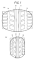
- FIG. 3 A typical example of the tread pattern according to the invention based on the above knowledge is shown in FIG. 3.
- this tread pattern has at least two circumferential grooves, two circumferential grooves 1a and 1b in the illustrated embodiment in a region from an equatorial plane O of the tire to an axially inner side during the mounting on a vehicle, and at least one circumferential groove, one circumferential groove 1 c in the illustrated embodiment in a region to an axially outer side.
- the circumferential groove 1b arranged nearest to the equatorial plane O of the tire among the circumferential grooves 1a and 1b arranged in the region to the axially inner side has a width wider by 20% or more than an average groove width defined by dividing a total groove width of the tire (total width of the circumferential grooves arranged in the tread) by the number of the circumferential grooves, and the circumferential groove 1a arranged toward a side of a tread end in the region of the axially inner side has a width corresponding to 90-110% of the average groove width, and the circumferential groove 1c in the region of the axially outer side has a width narrower by 10% or more than the average groove width.
- the drainage property is considerably improved by making the width of the circumferential groove 1b nearest to the equatorial plane of the tire by 20% or more than the average groove width.
- the groove width of the circumferential groove 1b is widened exceeding the 100% of the average groove width, it is feared that it is difficult to conduct drainage due to the crushing of the central portion of the circumferential groove 1b in the contact with ground, so that it is preferable that the upper limit of the increase of the groove width is 100% of the average groove width.
- the groove width is made narrower by 10% or more than the average groove width, whereby the ability of controlling the noise can be improved with the inclusion of widening the width of the circumferential groove 1b and further 1a.
- the width of the circumferential groove 1c is less than 3 mm, there is a fear not developing the function as a groove, so that the lower limit is preferable to be 3 mm.
- the circumferential groove 1a located at a side of the shoulder in the axially inner side in the mounting is low in the sensitivity to the columnar resonance, even if the groove width is widened or narrowed, the influence on the noise is less. In order to more improve the resistance to hydroplaning under a negative camber in the braking, therefore, it is sufficient to make the groove width wider to 10% than the average groove width. On the other hand, in order to improve the resistance to hydroplaning in the straight running, it is better to make the groove width narrower to 10% than the average groove width so as to improve the drainage property together with the groove of the axially outer side.
- the width of the circumferential groove at the axially outer side in the mounting on the vehicle is made to about 10% reduced from the average groove width, the drainage property at the axially outer side can be improved as compared with the case of being made narrower than 10% in similar way.
- the drainage efficiency of the circumferential groove becomes small as compared with the case that the maximum ground contact width is larger than the ground contact length in the circumferential direction. In other words, the drainage efficiency of the circumferential groove becomes large in case that the ground contact form is extremely horizontally long. Also, since the sensitivity to the columnar resonance is large in the axially outer side, it is frequent that when the number of the circumferential groove is one in the region of the axially outer side, the resistance to hydroplaning and the noise performance are improved.
- the amount of water reserved in the central region per unit ground contact width is larger by 20-45% than that in the adjacent region, so that the resistance to hydroplaning can be further improved by making the width of the circumferential groove 1b at the axially inner side wider by 20-45% than the average groove width.
- the difference between the maximum ground contact width and the circumferential ground contact length is large or the ground contact form is horizontally long, for example, if the flatness ratio of the tire is low or the load bearing is small, the drainage efficiency of the circumferential groove becomes large as compared with the case that the difference between the maximum ground contact width and the circumferential ground contact length is small.
- the resistance to hydroplaning can be more effectively improved when two circumferential grooves are arranged at the axially outer side.
- the amount of water reserved in the central region per unit ground contact width is larger by 25-55% than that in the adjacent region, so that the resistance to hydroplaning can be further improved by making the width of the circumferential groove 1b at the axially inner side wider by 25-55% than the average groove width.
- the ground contact length in the ground contact form becomes long at the axially inner side than at the equatorial plane of the tire.
- the drainage efficiency of the circumferential groove becomes maximum at such a position that the ground contact length is maximum, and further this position is a position in which the sensitivity to columnar resonance becomes low at an inner side from the equatorial plane of the tire as previously mentioned.
- the "overlapping" means an arrangement that the position mL is included in the circumferential groove 1b, and it is not necessarily required that the position mL is existent in the widthwise center of the circumferential groove 1b.
- the radial tire In the radial tire, it is effective to increase the strengths of the tread portion and the belt portion located inside the tread portion through flatening of the tire for enhancing the high-speed running performance, but in order to provide the steering stability on the wet road surface on such a tire, it is required to enhance the drainage property on the width-widened tread portion based on the flatening.
- a rib-based tread pattern in which grooves and the like are not too arranged in the tread center portion is adopted for utilizing high belt tension and high rigidity in the center portion through so-called hoop effect as is expected to develop gripping force and steering stability in case of running at high speed on the dry road surface or the like.
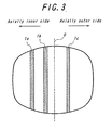
- FIG. 5 is a tread pattern for a passenger car tire according to the invention.
- the tread of this embodiment comprises four circumferential grooves 1a-1d extending along an equatorial plane O of the tire, among these circumferential grooves 1a-1d and tread ends T are defined land parts 2a and 2b each consisting of blocks toward both sides of the tread ends T, land parts 3a and 3b located at inner sides in the widthwise direction of the tire, and a rib-shaped land part 4 on the equatorial plane O of the tire.
- the land parts 3a and 3b have slant grooves 5a and 5b extending obliquely with respect to the equatorial plane O of the tire and opening to an outside in the widthwise direction of the tire. Furthermore, the rib-shaped land part 4 has a plurality of fine grooves 6 extending across the equatorial plane O of the tire.
- a center S of the rib-shaped land part 4 in the widthwise direction of the tire is positioned from the equatorial plane O of the tire toward such a side that a circumferential length of a tread ground contact region is elongated when the negative camber is applied to the tire (a side of existing a position mL of a maximum ground contact length of the tread).
- the rib-shaped land part 4 can be arranged in a high belt rigidity portion of producing a high belt tension through the aforementioned hoop effect at the tread center portion and of enlarging a ground contact area through the elongation of the ground contact length, which is effective to largely enhance the steering stability.
- the fine grooves 6 in the rib-shaped land part 4 so as not to concentrate the wearing in the rib-shaped land part 4 existing in the tread center portion through the high belt rigidity. That is, the circumferential strain accompanied with the rotation of the tire can be mitigated by the fine grooves 6, so that the wearing is suppressed in the release of strain produced in the leading time.
- the formation of the fine grooves 6 brings about the lowering of the rigidity in the rib-shaped land part 4 in the widthwise direction of the tire, so that it is required to suppress the lowering of the gripping force to a minimum level by establishing the mitigation of strain in the ground contacting and the rigidity in lateral direction. That is, the fine groove 6 is advantageous to have a portion extending in a direction inclined with respect to a radial direction of the tire tread so that the lateral rigidity can be held in the ground contact region while land parts defined by the fine grooves 6 escape in the circumferential direction and interfere with each other in the widthwise direction.
- the feature that the fine groove 6 has a portion extending in a direction inclined with respect to a radial direction of the tire tread means that the fine groove 6 is not uniformly extended in the radial direction and widthwise direction of the tire.
- the fine groove 6 is divided into, for example, three segments and the cut of each segment in the depth direction is inclined with respect to the radial direction of the tire and directions of the adjoining segments are opposite to each other.
- an angle ⁇ defined between the cuts of the segments is advantageous to be within a range of 5-30°.
- the cut may be extended in the inclination direction with respect to the radial direction of the tire while twisting, or the cut from the surface of the tread may be extended in a different direction on a halfway, or the cut from the surface of the tread may be divided into plural sections in the widthwise direction on a halfway and the extending directions may be made different among the divided sections.
- each of the fine grooves is discontinuous in the widthwise direction of the tire.
- the formation of the fine groove 6 extended in such a direction escapes the strain in the circumferential direction, while it is avoided to continue the groove in the widthwise direction of the tire, and as a result, the deformation of the fine groove can be suppressed to ensure the rigidity by the interference through adjoining walls defined and regulated in the widthwise direction of the tire.
- the fine groove 6 is inclined within a range of 5-55° with respect to the widthwise direction of the tire in order to make small a so-called pattern noise produced by contacting the land part with ground at the leading during the running of the tire. That is, when the angle is less than 5°, there is a fear that the fine groove is periodically coincident with a line of the ground contact form during the rotation of the tire to result in the occurrence of a large pattern noise. While, when it exceeds 55°, there is a fear that the rigidity of the rib-shaped land part 4 in the widthwise direction lowers to badly exert on the steering stability.
- the fine groove 6 is preferable to be opened at the surface of the tread from a viewpoint of controlling the wear of the tread center portion. Concretely, when the opening width is not more than 2 mm, the effect of reducing the strain in the circumferential direction can be sufficiently developed.
- the fine groove is preferable to be closed at the surface of the tread from a viewpoint of improving the steering stability.
- the same function and effect as in the fine groove 6 can be obtained by forming ellipsoidally recessed dimples 7 having an major axis in a direction crossing the equatorial plane O of the tire instead of the fine grooves 6 as shown in FIG. 7.
- a center of the major axis of the dimple 7 is preferable to be made coincident with the center of the rib-shaped land part 4 in the widthwise direction of the tire.
- a ground contact length of the shoulder portion at the axially inner side becomes longer than a ground contact length of the outer side, so that if a slight slip angle of toe-in or toe-out is applied at this state, the lateral slippage of the tire becomes large and the shoulder portion at the axially inner side excessively bears the lateral force, which is a factor of causing uneven wear that the shoulder portion at the axially inner side is much worn as compared with the shoulder portion at the axially outer side.
- a longitudinal deflection of the shoulder portion at the axially inner side becomes larger than that of the shoulder portion at the axially outer side, so that the width is widened and the width-widened region is drawn to receive force in the braking direction, which is also a factor of causing the uneven wear.
- the shoulder portion at the axially inner side is large in the deflection as compared with the shoulder portion at the axially outer side and becomes small in the rotating radius, which is drawn to receive force in the braking direction.
- the bearing of this force becomes larger in a region near to the ground contact end and a nucleus for uneven wear is easily produced in this region.
- the uneven wear produced in the shoulder portion at the axially inner side is hardly observed and noticed at a state of mounting on the vehicle by a driver, so that if the uneven wear is left to stand without a proper treatment, it progresses and finally is feared to be a cause of troubles such as tire burst and the like.
- FIG. 8 mainly explain the land part construction and do not accurately show the width of the circumferential groove.
- the groove width may be properly changed under the features of the invention.
- FIG. 8 is a developed view of a tread pattern shown by a front view of a tire at a posture of mounting on a vehicle.
- the interior structure of this tire is the same as in the general radial tire and an illustration thereof is omitted here.
- a tread TD are arranged at least two circumferential grooves, three circumferential grooves 1a, 1b and 1c in the illustrated embodiment continuously extending in a circumferential direction.
- land parts 2a and 2b defined by the circumferential grooves 1a, 1c and a tread end T the land part 2a located at an axially inner side mounted on the vehicle is rendered into a rib, and the land part 2b located at an axially outer side mounted on the vehicle is rendered into a land part row of blocks defined by lateral grooves 8, whereby a total volume of lateral grooves, which may be formed in the land part 2a (lateral groove is not formed in the illustrated embodiment), per unit width in a widthwise direction of the tread over a full circumference of the tread is made smaller than a total volume of lateral grooves 8 formed in the land part 2b at a side of the other tread end and hence the rigidity in the circumferential direction of the land part is made larger in the land part 2a than in the land part 2b.
- lateral grooves 9a and 9b are formed in the other two land part rows 3a, 3b defined by the three circumferential grooves, but it is not limited to the illustrated embodiment.
- a plurality of holes 10 separated from the circumferential groove 1a are formed in the land part 2a, whereby a volume of concave portion in a zone ranging from a widthwise center line Ci of the land part 2a to the side of the tread end T is made larger than a volume of concave portion in a zone ranging from the center line Ci to a side opposite to the tread end T.
- the rigidity in the circumferential direction of the land part 2a is made larger than the rigidity in the circumferential direction of the land part 2b, whereby the land part 2 a is subjected to a compression deformation in the ground contact face to prolong the ground contact length and the lateral grooves are contracted to make the rotating radius small and a force opposite to the forward running direction of the vehicle, i.e. a braking force is applied to the shoulder portion of the land part 2a having a large rotating radius, and hence there can be prevented the occurrence of uneven wear.
- lateral grooves which may be formed in the land part 2a
- the term "lateral grooves, which may be formed in the land part 2a" includes a case that the lateral grooves are not formed as in the illustrated embodiment. In the latter case, the total volume of the lateral grooves is naturally zero.
- the lateral grooves may be formed in the land part 2a at the number smaller than in the land part 2b under a condition that the rigidity in the circumferential direction is large as compared with the land part 2b.
- lateral grooves 9a, 9b are formed in the two land part rows 3a, 3b defined by the three circumferential grooves 1a, 1b and 1c at an inside from the land parts 2a, 2b in the widthwise direction, respectively, in which edges of these grooves can be effectively contributed to increase of braking force and traction force and also the drainage performance in the central region of the tread can be improved.
- the hole 10 decreases the shear rigidity of a zone provided with the holes to make the bearing of this zone on lateral force small and suppress the occurrence of reaction force. Also, even if the zone is drawn in the braking direction, the occurrence of reaction force to the braking force can be suppressed to control the occurrence of uneven wear.
- a maximum dept h of the hole 10 is made to not less than 1/3 of a depth of the circumferential groove 1a, 1b, 1c, whereby the effect of suppressing the occurrence of uneven wear by the arrangement of the holes 10 can be ensured even if the wearing of the tire progresses.
- the definition of depth of the hole 10 is based on the depth of the circumferential groove adjacent thereto (1a in the illustrated embodiment).
- the upper limit of the maximum depth of the hole 10 is preferable to be a depth arriving at a radially outside of 1 mm from an outermost layer of a belt for ensuring a rubber gauge between the belt layer and the groove bottom.
- the depths of the circumferential grooves 1a, 1b and 1c it is desirable that the circumferential grooves 1a and 1b are deepened for improving the resistance to hydroplaning during the straight running, while the circumferential groove 1c is deepened for improving the resistance to hydroplaning during the cornering.
- the volume of the concave portion is made larger in the zone ranging from the center line Ci of the land part 2a at the axially inner side to the side of the tread end than in the zone ranging from the center line Ci to the side opposite to the tread end, whereby the effect of suppressing the uneven wear can be enhanced in the zone side the tread end easily causing the uneven wear.
- the land part 2a at the axially inner side mounted on the vehicle is divided by a fine-width circumferential 11 into a widthwise outer portion 12 and a widthwise inner portion 13 in the tread, and a width w of the widthwise outer portion 12 is made narrower than a width w0 of the widthwise inner portion 13 and is not more than 1/10 of a tread width W.
- the widthwise outer portion 12 in the vicinity of the ground contact end most easily causing the uneven wear is separated from the widthwise inner portion 13, whereby the growth of wear from the outer portion to the inner portion can be suppressed.
- the width W of the widthwise outer portion 12 is made narrower than the width w of the widthwise inner portion 13 and is not more than 1/10 of the tread width W, whereby the volume of uneven wear can be decreased to maintain a good appearance.
- At least one curvature center C1 among curvature centers of curves constituting a profile S1 of a side face of the widthwise outer portion 12 at a section in the widthwise direction of the tire is positioned at an outer side of the tire for the profile S1, while a curvature center C2 of a curve constituting a profile S2 of the widthwise inner portion 13 is positioned at an inner side of the tire for the profile S2.
- the volume of uneven wear at the widthwise outer portion 12 in the vicinity of the ground contact end most easily causing the uneven wear can be more decreased to maintain the good appearance.
- the width w10 of the fine-width circumferential groove 11 is gradually widened from the groove bottom toward the side of the tread surface.
- the tread construction is preferable that at least a part of the zone having the plural holes 10 in the widthwise inner portion 13 of the land part 2a at the axially inner side is contacted with ground under an action of a load corresponding to not less than 70% of a maximum load capacity of the tire.
- the opening sizes R of the holes 10 is made large in the widthwise inner portion 13 of the land part 2a at the axially inner side as they are separated apart from the equatorial plane of the tire.
- the effect of suppressing the occurrence of uneven wear and the growth thereof can be made large by the formation of the above plural holes 10 as the large bearing of lateral force or braking force approaches to the ground contact end. Also, when the holes 10 are arranged in a zone effective for the suppression of uneven wear and are not arranged in a portion other than this zone as far as possible, it is possible to well maintain the steering stability and the tread durability in the portion other than the above zone.
- a distance Q among mutually plural holes 10 in the widthwise inner portion 13 of the land part 2a at the axially inner side is made small as they are separated apart from the equatorial plane of the tire.
- the effect of suppressing the uneven wear can be made large in the vicinity of the ground contact end, and it is possible to maintain good steering stability and tread durability by arranging the plural holes in only the zone effective for the suppression of uneven wear.
- the depth of the hole 10 is made deeper as the hole is separated apart from the equatorial plane of the tire. Even in this case, the effect of suppressing the uneven wear can be made large in the vicinity of the ground contact end, and it is possible to maintain good steering stability and tread durability by arranging the plural holes in only the zone effective for the suppression of uneven wear.
- the solid propagation sound is roughly divided into a road noise in which the tire is vibrated as a whole by subjecting to a forced input from the irregularity of the road surface and the vibrations are transmitted through a wheel axle to a vehicle body and then changed into a sound in an interior of the vehicle, and a pattern noise in which the tire is vibrated by a geometrical discontinuity of a tread pattern itself in the tire and the vibrations are transmitted through the wheel axle to the vehicle body and then changed into a sound in the interior of the vehicle.
- the inventors have made various studies on the solid transmission sound, and obtained a knowledge that the vibration characteristics of the wheel is an important factor for increasing the solid transmission sound. Also, it becomes clear that the transmission of vibrations from the tire to the vehicle is carried out from the tire tread portion through the pair of sidewall portions, pair of bead portions, wheel rim and wheel disc to the wheel axle in this order and the vibration transmitting characteristics transmitted from each shoulder portion of the tire tread to the wheel axle differ and the form thereof does not result from an offset direction of the wheel disc with respect to the wheel rim but results from the size and shape of the wheel itself.
- FIG. 10 is a developed view of a tread pattern shown as a front view when the tire assembled on the wheel and inflated under an air pressure is mounted on the vehicle.
- the interior structure of the tire is the same as in the general radial tire and the illustration thereof is omitted here.
- a tread TR are arranged at least three circumferential grooves 1a, 1b and 1c continuously extending in the circumferential direction, and a total volume of lateral grooves, which may be formed in the land part 2a located at a side mounted on the wheel and having a large transmission ratio (lateral groove is not formed in the illustrated embodiment) as to the land parts 2a, 2b defined by the circumferential grooves 1a and 1c and a tread end T, per unit width in the widthwise direction of the tread over a full circumference of the tread is made smaller than a total volume of lateral grooves 8 formed in the land part 2b located at the side of the other tread end.
- slant grooves 9a, 9b are formed in two land parts 3a, 3b defined by the three circumferential grooves 1a, 1b and 1c, respectively, but it is not limited to such an illustrated embodiment.
- the land part 2a is provided with a fine-width circumferential groove 11 extending continuously and linearly in the circumferential direction of the tread, in which the land part 2a is divided into two portions through the fine-width circumferential groove 11 in the widthwise direction of the tread.
- an outer portion 12a from the fine-width circumferential groove 11 in the widthwise direction of the tread is rendered into a narrow-width rib
- an inner portion 13 from the fine-width circumferential groove 11 in the widthwise direction of the tread is provided with plural holes 10 separated apart from the circumferential groove 1a and the fine-width circumferential groove 11.
- sipes 14 may be formed in the widthwise inner portion 13 of the tread at equal intervals in the circumferential direction of the tread.
- the total volume of the lateral grooves in the land part 2a is made smaller than the total volume of the lateral grooves 8 in the land part 2b, whereby the lateral grooves as a discontinuous component in the circumferential direction at the land part 2a having a large vibration transmission characteristic can be made less and the occurrence of pattern noise produced in the contacting of the lateral groove with ground can be prevented.
- lateral grooves which may be formed in the land part 2a
- the term "lateral grooves, which may be formed in the land part 2a" includes a case that the lateral grooves are not formed as in the illustrated embodiment. In the latter case, the total volume of the lateral grooves is naturally zero.
- the fine-width circumferential groove 11 and the plural holes 10 are lowered the compression rigidity of the land part 2a, whereby the input from the irregularity of the road surface to the tire is decreased to suppress vibrations transmitted to the wheel axle and hence the road noise transmitted to the vehicle interior can be reduced.
- the fine-width circumferential groove 11 and the plural holes 10 do not form the discontinuous portion with respect to the circumferential direction of the tread different from the lateral groove, so that the occurrence of the pattern noise can be also suppressed.
- the compression rigidity of the widthwise inner portion 13 of the tread can be further lowered, whereby the road noise can be further reduced.
- the width w10 of the fine-width circumferential groove 11 is gradually widened from the groove bottom toward the side of the tread surface.
- an opening size R of each of the holes 10 formed in the widthwise inner portion 13 of the tread is made larger apart from the equatorial plane O of the tire, and a distance Q between mutual holes 10 is made smaller apart from the equatorial plane O of the tire, and a depth of the holes 10 is made deeper apart from the equatorial plane O of the tire.
- the compression rigidity of the widthwise inner portion 13 of the tread provided with the plural holes 10 in the radial direction of the tire can be lowered toward the ground contact end at a side of a portion of the wheel mounted having a large transmission ratio. More effectively, the input from the irregularity of the road surface to the tire can be decreased to control vibrations transmitted to the wheel axle and reduce the road noise transmitted to the vehicle interior. Also, the holes are arranged in a zone effective for the reduction of the road noise but are not arranged in a portion of the tread other than the above zone as far as possible, whereby it is made possible to well keep the steering stability and tread durability in such a portion.
- At least one curvature center C1 among curvature centers of a curve constituting a profile S1 of a side face of the widthwise outer portion 12 is located at an outside of the profile S1 in a section in the widthwise direction of the tire, while a curvature center C2 of a curve constituting a profile S2 of the widthwise inner portion is located at an inside of the profile S2.
- the volume of uneven wear in the widthwise outer portion 12 can be decreased to well maintain the appearance.
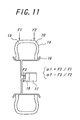
- FIG. 11 is a view schematically illustrating a method of measuring vibration transmitting characteristics of a wheel according to the invention. By conducting such a measurement can be easily and surely specified a land part located at a side having a large transmission ratio in the mounting on the wheel.
- a wheel 16 mounted with a tire 15 having a widthwise sectional shape symmetrical with respect to an equatorial plane of the tire is attached to an axle member 18 provided with a road cell 17, and vibrations are applied to each of shoulder portions 19, 20 of the tire tread at different frequencies, and an input F3 to the axle member is measured as these vibration forces are made as inputs F1 and F2, and then transmission ratios ⁇ 1 and ⁇ 2 by dividing F3 by F1, F2 are determined every each frequency and each of these transmission ratios ⁇ 1, ⁇ 2 is averaged to measure an average value of the transmission ratios ⁇ 1, ⁇ 2 to judge whether either average value of these transmission ratios is large.
- a side having large vibration transmission characteristics in the wheel can be specified by accurately judging either of the shoulder portions 19, 20 of the tire tread at a given frequency zone is large in the contribution to the input to the axle member 18, and it is possible to effectively locate various countermeasures at tire side for suppressing solid propagation sound to the wheel.
- the given frequency zone is made 300-1000 Hz.
- the side having a large transmission ratio to the wheel can be specified more accurately.
- the effective ground contact area at either axially inner side or axially outer side mounted on the vehicle is made larger than that of the other side, and also at a posture inflated under the normal air pressure, the radial distance from a tangential line on the outer surface of the tread perpendicular to the equatorial plane of the tire is made larger at the side having a small effective ground contact area than at the other side in view of the control of conicity force, which is easily caused in a tire having a asymmetrical pattern.
- the radial distance from the outer surface of the tread perpendicular to the equatorial plane of the tire to each ground contact end is made larger at the side having a small effective ground contact area than at the other side, whereby the widthwise shearing force generated in the tread shoulder portion located at a side having a large radial distance is contributed to offset the conicity force generated at the side having a large effective ground contact area, and particularly the steering stability at a small steering angle is improved.
- the ground contact face of the tread is schematically shown in FIG. 12(a) by making the negative ratios at the axially inner side and the axially outer side in the ground contact face of the tread different from each other, under a state that the tire is assembled on an approved rim and inflated under a normal air pressure and loaded under a mass corresponding to the maximum load capacity, when the effective ground contact area at the axially outer side S out shown by oblique lines in the figure is made larger than the effective ground contact area at the axially inner side S in , in order to suppress the occurrence of conicity force directing to the direction of the axially outer side, it is effective that as schematically shown by a section in the widthwise direction of the tire at a state of inflating under the normal air pressure in FIG.
- the tire is constructed, for example, by selecting a shape of an inner surface of a vulcanization mold or the like so that radial distances H in , H out from a tangential line L on the outer surface of the tire perpendicular to the equatorial plane O of the tire to ground contact edges of the tread EI, EO is made larger at the axially inner side having a small effective ground contact area (H in >H out ).
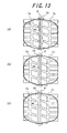
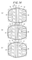
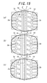
- Radial tires having tread patterns shown in FIGS. 13-15 and tire sizes of 205/65 R15 in FIG. 13, 205/55 R16 in FIG. 14 and 225/55 R16 in FIG. 15 are prepared according to the following various specifications.
- constructions other than circumferential groove(s), i.e. land parts defined between mutual circumferential grooves and between circumferential groove and tread end and lateral grooves and slant grooves arranged in the land parts and extending across an equatorial plane of the tire are the same as a basic specification.
- a ground contact form shown by a heavy line in each figure is a case that a camber angle is applied to a front wheel of the vehicle.
- circumferential grooves 1a-1c there are three circumferential grooves 1a-1c, in which the circumferential groove 1b is arranged on the equatorial plane O of the tire and the circumferential grooves 1a, 1c are arranged at positions each separated apart from both sides thereof at an equal distance. All of these circumferential grooves have a rectangular section of 8 mm in groove width and 8 mm in depth.
- Invention Example 1-1 has a rectangular section in which a center position of each circumferential groove is the same as in Conventional Example 1-2, but the groove width is circumferential groove 1a: 8.0 mm, circumferential groove 1b: 9.6 mm and circumferential groove 1c: 6.4 mm from the axially inner side and the groove depth is 8 mm.
- Invention Example 1-2 has a rectangular section in which a center position of each circumferential groove is the same as in Conventional Example 1-2, but the groove width is circumferential groove 1a: 8.8 mm, circumferential groove 1b: 9.6 mm and circumferential groove 1c: 5.6 mm from the axially inner side and the groove depth is 8 mm.
- Example 1-3 has a rectangular section in which a center position of each circumferential groove is the same as in Conventional Example 1-2, but the groove width is circumferential groove 1a: 7.2 mm, circumferential groove 1b: 9.6 mm and circumferential groove 1c: 7.2 mm from the axially inner side and the groove depth is 8 mm.
- Comparative Example 1-1 has a rectangular section in which a center position of each circumferential groove is the same as in Conventional Example 1-2, but the groove width is circumferential groove 1a: 8.0 mm, circumferential groove 1b: 8.8 mm and circumferential groove 1c: 7.2 mm from the axially inner side and the groove depth is 8 mm.
- Comparative Example 1-2 has a rectangular section in which a center position of each circumferential groove is the same as in Conventional Example 1-2, but the groove width is circumferential groove 1a: 9.2 mm, circumferential groove 1b: 9.6 mm and circumferential groove 1c: 5.2 mm from the axially inner side and the groove depth is 8 mm.
- Comparative Example 1-3 has a rectangular section in which a center position of each circumferential groove is the same as in Conventional Example 1-2, but the groove width is circumferential groove 1a: 6.8 mm, circumferential groove 1b: 9.6 mm and circumferential groove 1c: 7.6 mm from the axially inner side and the groove depth is 8 mm.
- Example 1-4 ha a rectangular section in which a center position of each circumferential groove is the same as in Conventional Example 1-2, but the groove width is circumferential groove 1a: 7.2 mm, circumferential groove 1b: 11.6 mm and circumferential groove 1c: 5.2 mm from the axially inner side and the groove depth is 8 mm.
- Comparative Example 1-4 has a rectangular section in which a center position of each circumferential groove is the same as in Conventional Example 1-2, but the groove width is circumferential groove 1a: 7.2 mm, circumferential groove 1b: 12.0 mm and circumferential groove 1c: 4.8 mm from the axially inner side and the groove depth is 8 mm.
- an average groove width in the tread pattern of FIG. 13 is 8 mm.
- Each of the above tires is assembled on a rim of 6J-15 and mounted on a passenger car after an internal pressure is adjusted to 220 kPa.
- a camber to ground is -0.4° in a front wheel and -0.8° in a rear wheel.
- An acceleration test of the vehicle from a speed of 50 km/h in a pool having a water depth of 6 mm is carried out to evaluate a speed of causing the hydroplaning by a test driver.
- the evaluation results are represented by an index of hydroplaning speed, in which the larger the index value, the better the result.
- a braking test is carried out on a wet road surface having a water depth of 2 mm from a speed of 100 km/h to evaluate the hydroplaning in the braking.
- the evaluation result is represented by an index, in which the larger the index value, the better the result.
- a noise is measured around a driver's ear in the running at a speed of 60 km/h on a smooth road surface, in which the larger the index value, the better the result.
- Example 1-1 100 100 100 Conventional Example 1-2 95 102 102 Invention Example 1-1 105 105 105 Invention Example 1-2 102 108 108 Invention Example 1-3 108 103 102 Comparative Example 1-1 97 103 103 Comparative Example 1-2 99 108 102 Comparative Example 1-3 103 98 98 Invention Example 1-4 102 102 103 Comparative Example 1-4 99 99 102
- Comparative Example 1-1 is lacking in the resistance to hydroplaning though the width of the center circumferential groove is +10% of the average groove width.
- Comparative Example 1-2 the resistance to hydroplaning in the braking is good as compared with Invention Example 1-2 because the circumferential groove at the axially inner side is 115% of the average groove width, but the index of hydroplaning speed is deteriorated because the width of the circumferential groove at the axially outer side becomes too small.
- the width of the circumferential groove at the axially outer side is -5% of the average groove width, and such a wide groove width at the axially outer side is disadvantageous in the noise, while the width of the circumferential groove at the axially inner side is narrow and the resistance to hydroplaning in the braking is poor.
- the circumferential groove at the axially inner side is +50% of the average groove width, and hence the groove at the axially outer side is too narrow and the resistance to hydroplaning is deteriorated.
- circumferential grooves 1a-1d there are four circumferential grooves 1a-1d, in which circumferential grooves 1b and 1c are arranged at both sides of a rib 2 disposed at its width center on the equatorial plane O of the tire and having a width of 20 mm, and circumferential grooves 1a and 1d are arranged at outsides of land parts 3a, 3b disposed at the outside of the groove and having a width of 20 mm. All of these circumferential grooves have a rectangular section of 8 mm in groove width and 8 mm in depth.
- Invention Example 1-5 has a rectangular section in which a center position of each circumferential groove is the same as in Conventional Example 1-4, but the groove width is circumferential groove 1a: 8.0 mm, circumferential groove 1b: 9.6 mm, circumferential groove 1c: 7.2 mm and circumferential groove 1d: 7.2 mm from the axially inner side and the groove depth is 8 mm.
- Invention Example 1-6 has a rectangular section in which a center position of each circumferential groove is the same as in Conventional Example 1-4, but the groove width is circumferential groove 1a: 8.8 mm, circumferential groove 1b: 9.6 mm, circumferential groove 1c: 6.8 mm and circumferential groove 1d: 6.8 mm from the axially inner side and the groove depth is 8 mm.
- Comparative Example 1-5 has a rectangular section in which a center position of each circumferential groove is the same as in Conventional Example 1-4, but the groove width is circumferential groove 1a: 8.8 mm, circumferential groove 1b: 8.8 mm, circumferential groove 1c: 7.2 mm and circumferential groove 1d: 7.2 mm from the axially inner side and the groove depth is 8 mm.
- Comparative Example 1-6 has a rectangular section in which a center position of each circumferential groove is the same as in Conventional Example 1-4, but the groove width is circumferential groove 1a: 9.2 mm, circumferential groove 1b: 9.6 mm, circumferential groove 1c: 6.6 mm and circumferential groove 1d: 6.6 mm from the axially inner side and the groove depth is 8 mm.
- Comparative Example 1-7 has a rectangular section in which a center position of each circumferential groove is the same as in Conventional Example 1-4, but the groove width is circumferential groove 1a: 7.2 mm, circumferential groove 1b: 9.6 mm, circumferential groove 1c: 7.6 mm and circumferential groove 1d: 7.6 mm from the axially inner side and the groove depth is 8 mm.
- the average groove width in the tread pattern of FIG. 14 is 8 mm.
- Each of the above tires is assembled on a rim of 6.5J-16 and mounted on a passenger car after an internal pressure is adjusted to 220 kPa.
- a camber to ground is -0.5° in a front wheel and -0.8° in a rear wheel.
- An acceleration test of the vehicle from a speed of 50 km/h in a pool having a water depth of 6 mm is carried out to evaluate a speed of causing the hydroplaning by a test driver.
- the evaluation results are represented by an index of hydroplaning speed, in which the larger the index value, the better the result.
- a braking test is carried out on a wet road surface having a water depth of 2 mm from a speed of 100 km/h to evaluate the hydroplaning in the braking.
- the evaluation result is represented by an index, in which the larger the index value, the better the result.
- a noise is measured around a driver's ear in the running at a speed of 60 km/h on a smooth road surface, in which the larger the index value, the better the result.
- Comparative Example 1-5 is lacking in the resistance to hydroplaning as compared with Conventional Example 1-4 though the width of the center circumferential groove is +10% of the average groove width.
- Comparative Example 1-6 the resistance to hydroplaning in the braking is good as compared with Invention Example 1-6 because the circumferential groove at the axially inner side is 115% of the average groove width, but the index of hydroplaning speed is deteriorated because the width of the circumferential groove at the axially outer side becomes too small.
- the width of the circumferential groove at the axially outer side is -5% of the average groove width, and such a wide groove width at the axially outer side is disadvantageous in the noise, while the width of the circumferential groove at the axially inner side is narrow and the resistance to hydroplaning in the braking is poor.
- circumferential grooves 1a-1d there are four circumferential grooves 1a-1d, in which circumferential grooves 1b band 1c are arranged at both sides of a rib 2 disposed at its width center on the equatorial plane O of the tire and having a width of 20 mm, and circumferential grooves 1a and 1d are arranged at outsides of land parts 3a, 3b disposed at the outside of the groove and having a width of 20 mm. All of these circumferential grooves have a rectangular section of 8 mm in groove width and 8 mm in depth.
- Invention Example 1-7 has a rectangular section in which a center position of each circumferential groove is the same as in Conventional Example 1-6, but the groove width is circumferential groove 1a: 8.0 mm, circumferential groove 1b: 10.4 mm, circumferential groove 1c: 6.8 mm and circumferential groove 1d: 6.8 mm from the axially inner side and the groove depth is 8 mm.
- Invention Example 1-8 has a rectangular section in which a center position of each circumferential groove is the same as in Conventional Example 1-6, but the groove width is circumferential groove 1a: 8.0 mm, circumferential groove 1b: 12.4 mm, circumferential groove 1c: 5.8 mm and circumferential groove 1d: 5.8 mm from the axially inner side and the groove depth is 8 mm.
- Comparative Example 1-8 has a rectangular section in which a center position of each circumferential groove is the same as in Conventional Example 1-6, but the groove width is circumferential groove 1a: 8.8 mm, circumferential groove 1b: 13.2 mm, circumferential groove 1c: 5.4 mm and circumferential groove 1d: 5.4 mm from the axially inner side and the groove depth is 8 mm.
- the average groove width in the tread pattern of FIG. 15 is 8 mm.
- Each of the above tires is assembled on a rim of 7.5J-16 and mounted on a passenger car after an internal pressure is adjusted to 210 kPa.
- a camber to ground is -0.3° in a front wheel and -0.5° in a rear wheel.
- An acceleration test of the vehicle from a speed of 50 km/h in a pool having a water depth of 6 mm is carried out to evaluate a speed of causing the hydroplaning by a test driver.
- the evaluation results are represented by an index of hydroplaning speed, in which the larger the index value, the better the result.
- a braking test is carried out on a wet road surface having a water depth of 2 mm from a speed of 100 km/h to evaluate the hydroplaning in the braking.
- the evaluation result is represented by an index, in which the larger the index value, the better the result.
- a noise is measured around a driver's ear in the running at a speed of 60 km/h on a smooth road surface, in which the larger the index value, the better the result.
- Comparative Example 1-8 is lacking in the resistance to hydroplaning as compared with Conventional Example 1-6 though the width of the center circumferential groove is +65% of the average groove width but the width of the circumferential groove at the axially outer side becomes too small.
- a radial tire for passenger car having a tread pattern shown in FIG. 5 and a tire size of 205/65R15.
- the depth of all of four circumferential groove is 8 mm
- the width is 8 mm in the circumferential grooves 1a and 1d
- 6.4 mm in the circumferential groove 1c at a side of decreasing the ground contact length (corresponding to an axially outer side).
- an offset amount of a land part center S with respect to the equatorial plane O of the tire is 5 mm
- the ground contact form shown by a heavy line is a case of applying a negative camber angle of 0.5°.
- fine grooves 6 are inclined at 15° with respect to a widthwise direction of the tire. As shown in FIG. 6, the fine groove 6 is cut into a rib-shaped land part 4 having a width of 18 mm over a full width thereof at a depth of 10 mm in a radial direction of the tire and at an inclination angle of ⁇ 22.5° with respect to the radial direction of the tire. Also, an opening width of the fine groove 6 is 0.4 mm, and a distance between mutual fine grooves 6 is 30 mm.
- a radial tire for passenger car having a tread pattern shown in FIG. 7 and a tire size of 205/65R15.
- the tread pattern shown in FIG. 7 is the same as in FIG. 5 except that dimples 7 each having a major axis inclined at 15° with respect to the widthwise direction of the tire are arranged in the rib-shaped land part 4 instead of the fine groove 6.
- the dimple 7 has a major axis of 13 mm and minor axis of 3 mm, and a distance between mutual dimples 7 is 30 mm.
- FIG. 16 is a tread pattern for the comparison, and a basic pattern thereof is the same as in Invention Example 2-1, but is different in points that the fine groove 6 is not arranged in the rib-shaped land part 4 and that the widthwise center of the rib-shaped land part 4 is located on the equatorial plane O of the tire. Moreover, the depth of the circumferential grooves is 8 mm, and the width is 8 mm in the circumferential grooves 1a and 1d, and 7 mm in the circumferential grooves 1b and 1c.
- At least two circumferential grooves, three circumferential grooves 1a, 1b, 1c in the illustrated embodiment (width 1a: 8.0 mm, 1b: 9.6 mm and 1c: 6.4 mm) extending continuously in a circumferential direction are arranged in a tread TR, and as to land parts.
- the land part 2a located at an axially inner side is shaped in a rib and the land part 2b located at an axially outer side is provided with lateral grooves 8 to form a land part row of blocks, and a total volume of lateral grooves between both the land parts is made small in the land part 2a to make a rigidity of land part in the circumferential direction larger in the land part 2a than in the land part 2b.
- lateral grooves 9a and 9b are arranged in the other two land parts 3a and 3b defined among the three circumferential grooves, respectively.
- the land part 2a is provided with a plurality of holes 10 separated apart from the circumferential groove 1a, whereby a volume of concave portion in a zone ranging from a center line Ci of the land part 2a to a side of the tread end T is made larger than a volume of concave portion in a zone ranging from the center line Ci toward a side opposite to the tread end.
- the land part 2a located at the axially inner side in the mounting on the vehicle is divided by a fine-width circumferential groove 11 into a widthwise outer portion 12 and a widthwise inner portion 13, and a width (10 mm) of the widthwise outer portion 12 is made narrower than a width (20 mm) of the widthwise inner portion 13 and is not more than 1/10 of a tread width.
- a depth is 5.0 mm
- a width at groove bottom is 1.5 mm and a width at the tread surface is 2.6 mm.
- a width of the widthwise outer portion 12 is 2 mm
- a width of the widthwise inner portion 13 is 18 mm.
- holes 10 In the land part 12a at the axially inner side are arranged a plurality of holes 10 separated apart from the circumferential groove 1a and the fine-width circumferential groove 11.
- These holes 10 consists of two hole rows, in which widthwise outer holes have a diameter of 2.5 mm, a depth of 6 mm and a distance between centers of 7.5 mm, and the widthwise inner holes have a diameter of 1.5 mm, a depth of 6 mm and a distance between centers of 7.5 mm.
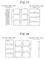
- a tread pattern of Invention Example 3-2 is standardized on Invention Example 3-1 as shown in FIG. 17, in which a hole row having a diameter of 2.5 mm, a depth of 6 mm and a distance between centers of 7.5 mm is arranged without forming the fine-width circumferential groove.
- lateral grooves are not arranged on a land part located in a side of the tread end at the axially outer side, and lateral grooves are arranged on a land part located in a side of the tread end at the axially inner side.
- a tread pattern of Comparative Example 3-3 is standardized on Invention Example 3-1 as shown in FIG. 20, in which the width of the widthwise outer portion 12 is 14 mm and the width of the widthwise inner portion 13 is 6 mm, and a hole row having a diameter of 2.5 mm, a depth of 6 mm and a distance between centers of 7.5 mm is arranged in the widthwise inner portion 13.
- a tread pattern of Comparative Example 3-4 is standardized on Invention Example 3-1 as shown in FIG. 21, in which the fine-width circumferential groove is not arranged, and a hole row having a diameter of 3.0 mm, a depth of 6 mm and a distance between centers of 7.5 mm, and a hole row having a diameter of 2.0 mm, a depth of 6 mm and a distance between centers of 7.5 mm, and a hole row having a diameter of 1.0 mm, a depth of 6 mm and a distance between centers of 7.5 mm are arranged from a widthwise inner side in this order.
- a tread pattern of Comparative Example 3-5 is standardized on Invention Example 3-1 as shown in FIG. 22, in which the holes are not formed.
- the performance is evaluated by measuring a difference between worn amount of the land part at the axially inner side and worn amount of the land part at the axially outer side and represented by an index on the basis that the measured result of Comparative Example 3-1 is 100, in which the smaller the index value, the better the result.
- Comparative Example 3-2 When Comparative Example 3-2 is compared with Comparative Example 3-1, it is understood that if the lateral groove component in the land part at the axially outer side is made small and this land part is divided by the fine-width circumferential groove into the widthwise inner portion and the widthwise outer portion and the holes are formed in these portions, lateral force in the cornering can not be born and hence the performance of suppressing the uneven wear is rather deteriorated. In this case, the outer portion located at the outside of the fine-width circumferential groove does not function against the lateral force and hence the uneven wear is caused in the inner portion and the appearance is deteriorated.
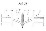
- FIG. 10 For the purpose of measuring the effect of reducing interior noise in the pneumatic tire according to the invention, there are provided one kind of a tire having a tire size of 205/65R15 and a tread pattern shown in FIG. 10 (Invention Example 4-1) and two kinds of tires having tread patterns shown in FIGS. 23 and 24 (Comparative Examples 4-1 and 4-2).
- Each of these tires is inflated under an air pressure of 200 kPa and assembled onto an aluminum wheel having a size of 14x6JJ (transmission ratio: +3 dB at an overall (total sound pressure level)), in which the transmission ratio is larger in a rear side (axially inner side) than in a front side (axially outer side), and mounted on a domestic FF car of 2000 cc.
- a running test on a rough road surface is carried out at 60 km/h, during which noise level at a zone value of 300-800 Hz is measured at a position corresponding to a left ear of a driver.
- the widths of the circumferential grooves in all of the tires are 8.0 mm, 9.6 mm and 7.4 mm from a left side of the figure in this order.
- At least two circumferential grooves, particularly three circumferential grooves 52 in the figure continuously extending in a circumferential direction are arranged in a tread 51, and lateral grooves 55, 56 are arranged in a land part 53 of a widthwise end side located at a side having a large vibration transmission characteristic of a wheel to be mounted and a land part 54 of the other widthwise end side among land parts defined by these circumferential grooves 52 so as to be made total volumes equal to each other, and slant grooves 59, 60 are arranged in two land parts 57, 58 defined inward in the widthwise direction by the three circumferential grooves 52, respectively.
- Comparative Example 4-2 As shown in FIG. 24, the tire of Invention Example 4-1 is mounted on a wheel so as to turn the direction of the pattern inside out. Interior noise Invention Example 4-1 ⁇ 1.5 dB Comparative Example 4-1 standard value Comparative Example 4-2 + 0.4 dB
- Comparative Example 4-2 is a case that the tire of Invention Example 4-1 is mounted on the wheel so as to position the land part having a small total volume of lateral grooves and provided with fine-circumferential groove and holes to a side having a small transmission ratio of wheel, from which it is understood that the number of lateral grooves in the land part arranged at a side having a large transmission ratio of wheel becomes large and the geometrical discontinuity increases and hence the pattern noise increases and the interior noise is rather deteriorated as compared with Comparative Example 4-1.
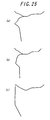
- wheels A, B, C having a sectional shape shown in FIG. 25 and an offset value of a disc of 45 mm with respect to a rim having a size of 14x6JJ and provided with a tire having a widthwise sectional shape symmetric with respect to an equatorial plane of the tire.
- Each of these wheels is mounted on an axle portion provided with a load cell, and vibrations are applied to both shoulder portions of a tread of the tire by a vibration exciter to measure a vibration force as an input and a force measured at the axle portion as an output, and a function of transmission ratio responding to frequency is determined at each of front side and back side to determine a ratio of transmission ratio (back/front) every each frequency and calculate an average thereof at a frequency zone of 300-1000 Hz, from which a side having a large transmission characteristic of wheel is specified.
- Table 7 When a numerical value is 1, the transmission ratios at the front and back sides are the same, and when it exceeds 1, the transmission ratio at the back side is large, and when it is less than 1, the transmission ratio at the front side is large.
- Transmission ratio (back/front) Wheel A 1.0 Wheel B 0.8 Wheel C 2.95
- the side having a large transmission ratio of wheel can be accurately specified, and it is possible to effectively apply various countermeasures for suppressing the solid propagation sound.
- Invention Example 5-1 has a shape of a ground contact face of a tread shown in FIG. 12(a), in which three circumferential grooves having a depth of 8 mm (groove width is 8.0 mm, 9.6 mm and 7.4 mm from a left side of the figure in this order) are asymmetrically arranged at axially inner and outer sides, and a ratio of effective ground contact area at axially outer side S out to ground contact area at axially inner side Sin with respect to the equatorial plane O of the tire is 1.14, and a radial distance from a tangential line L on an outer surface of the tread at a position corresponding to 80% of a tread width W is 5.8 mm at the axially outer side and 6.2 mm at the axially inner side.
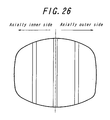
- Comparative Example 5-1 has a shape of a ground contact face of a tread shown in FIG. 26, in which three circumferential grooves having a depth of 8 mm are arranged symmetrically with respect to the equatorial plane of the tire, and the effective ground contact areas at the front and back sides are equal to each other, and the radial distance from the tangential line L on an outer surface of the tread at a position corresponding to 80% of a tread width W is substantially equal at the front and back sides.
- Comparative Example 5-2 has a shape of a ground contact face of a tread shown in FIG. 12(a), in which the radial distance from the tangential line L on an outer surface of the tread at a position corresponding to 80% of a tread width W is substantially equal at the front and back sides.
- the steering stability is evaluated by feeling in the running on a test circuit course, and the resistance to hydroplaning is evaluated by feeling in the straight running on a road surface having a water depth of 6 mm. Moreover, the larger the index value, the better the result.
- the conicity force is determined by averaging found values of 10 tires. Steering stability Resistance to hydroplaning Conicity force Invention Example 5-1 105 108 20 Comparative Example 5-1 100 100 18 Comparative Example 5-2 108 108 86
- Invention Example 5-1 develops high steering stability and resistance to hydroplaning and can control the conicity force to the same level as in the symmetrical pattern tire of Comparative Example 5-1.
- tires in which the resistance to hydroplaning and the controllability of tire noise, which have been a conflicting relation in the prior art, are established in a higher level.
Landscapes
- Engineering & Computer Science (AREA)
- Mechanical Engineering (AREA)
- Tires In General (AREA)
Applications Claiming Priority (9)
| Application Number | Priority Date | Filing Date | Title |
|---|---|---|---|
| JP2002254173 | 2002-08-30 | ||
| JP2002254053A JP4275371B2 (ja) | 2002-08-30 | 2002-08-30 | 空気入りタイヤ |
| JP2002254020 | 2002-08-30 | ||
| JP2002253645A JP4266600B2 (ja) | 2002-08-30 | 2002-08-30 | 非対称トレッドパターンを有するタイヤ |
| JP2002253645 | 2002-08-30 | ||
| JP2002254020A JP4428914B2 (ja) | 2002-08-30 | 2002-08-30 | 非対称トレッドパターンを有するタイヤおよびその装着方法 |
| JP2002254053 | 2002-08-30 | ||
| JP2002254173A JP4275372B2 (ja) | 2002-08-30 | 2002-08-30 | 空気入りタイヤ |
| PCT/JP2003/011163 WO2004024471A1 (fr) | 2002-08-30 | 2003-09-01 | Pneu a structure asymetrique de sculptures et procede de montage du pneu |
Publications (3)
| Publication Number | Publication Date |
|---|---|
| EP1541380A1 true EP1541380A1 (fr) | 2005-06-15 |
| EP1541380A4 EP1541380A4 (fr) | 2011-06-29 |
| EP1541380B1 EP1541380B1 (fr) | 2013-10-30 |
Family
ID=31999408
Family Applications (1)
| Application Number | Title | Priority Date | Filing Date |
|---|---|---|---|
| EP03795277.7A Expired - Fee Related EP1541380B1 (fr) | 2002-08-30 | 2003-09-01 | Pneu a structure asymetrique de sculptures et procede de montage du pneu |
Country Status (4)
| Country | Link |
|---|---|
| US (1) | US20050247388A1 (fr) |
| EP (1) | EP1541380B1 (fr) |
| CN (1) | CN1684844A (fr) |
| WO (1) | WO2004024471A1 (fr) |
Cited By (7)
| Publication number | Priority date | Publication date | Assignee | Title |
|---|---|---|---|---|
| EP1712377A1 (fr) * | 2004-01-16 | 2006-10-18 | Bridgestone Corporation | Pneumatique |
| EP2159080A1 (fr) | 2008-08-29 | 2010-03-03 | Continental Reifen Deutschland GmbH | Pneumatique |
| FR2962372A1 (fr) * | 2010-07-06 | 2012-01-13 | Michelin Soc Tech | Dispositif de protection de bande de roulement |
| WO2014067693A2 (fr) * | 2012-11-05 | 2014-05-08 | Continental Reifen Deutschland Gmbh | Profil de bande de roulement d'un pneumatique de véhicule |
| EP2960075A4 (fr) * | 2013-02-20 | 2016-10-19 | Bridgestone Corp | Pneumatique, et procédé de fabrication de celui-ci |
| EP2960074A4 (fr) * | 2013-02-20 | 2016-10-19 | Bridgestone Corp | Pneumatique, et procédé de fabrication de celui-ci |
| EP2602126B1 (fr) * | 2011-12-09 | 2018-01-10 | Continental Reifen Deutschland GmbH | Pneu de véhicule |
Families Citing this family (19)
| Publication number | Priority date | Publication date | Assignee | Title |
|---|---|---|---|---|
| WO2006033383A1 (fr) * | 2004-09-24 | 2006-03-30 | Bridgestone Corporation | Bandage pneumatique |
| JP4229965B2 (ja) * | 2006-11-14 | 2009-02-25 | 横浜ゴム株式会社 | ブレーキ制御方法およびブレーキ制御装置 |
| JP4195054B2 (ja) * | 2006-11-24 | 2008-12-10 | 横浜ゴム株式会社 | ブレーキ制御方法およびブレーキ制御装置 |
| ATE553935T1 (de) * | 2007-11-02 | 2012-05-15 | Bridgestone Corp | Radialluftreifen |
| JP5012675B2 (ja) * | 2008-06-04 | 2012-08-29 | 横浜ゴム株式会社 | タイヤの姿勢制御装置および方法 |
| CN102398481A (zh) * | 2010-09-14 | 2012-04-04 | 青岛黄海橡胶股份有限公司 | 轿车子午线轮胎胎面花纹 |
| JP2017024659A (ja) | 2015-07-27 | 2017-02-02 | 横浜ゴム株式会社 | 空気入りタイヤ |
| JP6496208B2 (ja) * | 2015-08-04 | 2019-04-03 | 住友ゴム工業株式会社 | 空気入りタイヤ |
| JP6575254B2 (ja) * | 2015-09-15 | 2019-09-18 | 住友ゴム工業株式会社 | 空気入りタイヤ |
| JP6772615B2 (ja) * | 2016-07-19 | 2020-10-21 | 横浜ゴム株式会社 | 空気入りタイヤ |
| FR3058928A1 (fr) * | 2016-11-22 | 2018-05-25 | Compagnie Generale Des Etablissements Michelin | Bande de roulement de pneu pour engin de genie civil comportant des creux de ventilation ameliores |
| JP6891515B2 (ja) * | 2017-01-31 | 2021-06-18 | 住友ゴム工業株式会社 | タイヤ |
| DE102017203011A1 (de) * | 2017-02-24 | 2018-08-30 | Continental Reifen Deutschland Gmbh | Fahrzeugluftreifen |
| CN106864177B (zh) * | 2017-02-24 | 2019-03-26 | 建大橡胶(中国)有限公司 | 一种休旅车非对称花纹轮胎 |
| JP7056392B2 (ja) * | 2018-06-13 | 2022-04-19 | 住友ゴム工業株式会社 | タイヤ |
| CN109203867B (zh) * | 2018-11-09 | 2020-10-27 | 青岛双星轮胎工业有限公司 | 胎面花纹及轮胎 |
| JP7205241B2 (ja) * | 2019-01-15 | 2023-01-17 | 住友ゴム工業株式会社 | タイヤ |
| WO2021137860A1 (fr) * | 2019-12-31 | 2021-07-08 | Compagnie Generale Des Etablissements Michelin | Pneu à sculpture hélicoidale avec des caractéristiques de nervure centrale inversée |
| JP2022154242A (ja) * | 2021-03-30 | 2022-10-13 | 住友ゴム工業株式会社 | タイヤ |
Citations (5)
| Publication number | Priority date | Publication date | Assignee | Title |
|---|---|---|---|---|
| US3286756A (en) * | 1961-12-18 | 1966-11-22 | Inverstment In Patent Dev S A | Automobile tire |
| JPH03220004A (ja) * | 1990-01-25 | 1991-09-27 | Bridgestone Corp | 空気入りラジアルタイヤ |
| US5213641A (en) * | 1989-03-27 | 1993-05-25 | Bridgestone Corporation | Pair of radial tires with directional and symmetrical tread patterns |
| JPH0648120A (ja) * | 1992-01-08 | 1994-02-22 | Bridgestone Corp | 空気入りタイヤ |
| EP1029712A1 (fr) * | 1999-02-20 | 2000-08-23 | Continental Aktiengesellschaft | Bandage pneumatique pour véhicule |
Family Cites Families (12)
| Publication number | Priority date | Publication date | Assignee | Title |
|---|---|---|---|---|
| JPS53133802A (en) * | 1977-04-26 | 1978-11-22 | Bridgestone Corp | Wear resistant radial pneumatic type for heavy load |
| JPH01314609A (ja) * | 1988-06-15 | 1989-12-19 | Yokohama Rubber Co Ltd:The | 空気入りタイヤ |
| EP0422902B1 (fr) * | 1989-10-12 | 1995-09-06 | Bridgestone Corporation | Bandage pneumatique radial |
| US5360043A (en) * | 1991-07-26 | 1994-11-01 | The Goodyear Tire & Rubber Company | Asymmetric tread for a tire |
| JPH05330313A (ja) * | 1992-05-29 | 1993-12-14 | Yokohama Rubber Co Ltd:The | 空気入りタイヤ |
| US5603785A (en) * | 1994-05-06 | 1997-02-18 | The Goodyear Tire & Rubber Company | Tire including two aquachannels on one side |
| DE4420316A1 (de) * | 1994-06-10 | 1995-12-14 | Continental Ag | Fahrzeugluftreifen mit symmetrischem Unterbau und asymmetrischer Lauffläche |
| JPH0885308A (ja) * | 1994-09-20 | 1996-04-02 | Yokohama Rubber Co Ltd:The | 空気入りラジアルタイヤ |
| US5735979A (en) * | 1995-07-24 | 1998-04-07 | Dunlop Tire Corporation | Pneumatic tire with asymmetric tread profile |
| JP3177466B2 (ja) | 1997-02-06 | 2001-06-18 | 住友ゴム工業株式会社 | 空気入りタイヤ |
| PT1189770E (pt) * | 1999-06-30 | 2004-06-30 | Pirelli | Pneu de elevado desempenho para um veiculo com motor |
| JP3443400B2 (ja) * | 2000-12-06 | 2003-09-02 | 住友ゴム工業株式会社 | 空気入りタイヤ |
-
2003
- 2003-09-01 WO PCT/JP2003/011163 patent/WO2004024471A1/fr active Application Filing
- 2003-09-01 EP EP03795277.7A patent/EP1541380B1/fr not_active Expired - Fee Related
- 2003-09-01 US US10/526,084 patent/US20050247388A1/en not_active Abandoned
- 2003-09-01 CN CNA038230801A patent/CN1684844A/zh active Pending
Patent Citations (5)
| Publication number | Priority date | Publication date | Assignee | Title |
|---|---|---|---|---|
| US3286756A (en) * | 1961-12-18 | 1966-11-22 | Inverstment In Patent Dev S A | Automobile tire |
| US5213641A (en) * | 1989-03-27 | 1993-05-25 | Bridgestone Corporation | Pair of radial tires with directional and symmetrical tread patterns |
| JPH03220004A (ja) * | 1990-01-25 | 1991-09-27 | Bridgestone Corp | 空気入りラジアルタイヤ |
| JPH0648120A (ja) * | 1992-01-08 | 1994-02-22 | Bridgestone Corp | 空気入りタイヤ |
| EP1029712A1 (fr) * | 1999-02-20 | 2000-08-23 | Continental Aktiengesellschaft | Bandage pneumatique pour véhicule |
Non-Patent Citations (1)
| Title |
|---|
| See also references of WO2004024471A1 * |
Cited By (13)
| Publication number | Priority date | Publication date | Assignee | Title |
|---|---|---|---|---|
| EP1712377A1 (fr) * | 2004-01-16 | 2006-10-18 | Bridgestone Corporation | Pneumatique |
| EP1712377A4 (fr) * | 2004-01-16 | 2008-11-05 | Bridgestone Corp | Pneumatique |
| EP2159080A1 (fr) | 2008-08-29 | 2010-03-03 | Continental Reifen Deutschland GmbH | Pneumatique |
| DE102008044921A1 (de) | 2008-08-29 | 2010-03-04 | Continental Reifen Deutschland Gmbh | Fahrzeugluftreifen |
| FR2962372A1 (fr) * | 2010-07-06 | 2012-01-13 | Michelin Soc Tech | Dispositif de protection de bande de roulement |
| US10000093B2 (en) | 2010-07-06 | 2018-06-19 | Christophe Gayton | Tread protection device |
| EP2602126B1 (fr) * | 2011-12-09 | 2018-01-10 | Continental Reifen Deutschland GmbH | Pneu de véhicule |
| WO2014067693A3 (fr) * | 2012-11-05 | 2014-07-03 | Continental Reifen Deutschland Gmbh | Profil de bande de roulement d'un pneumatique de véhicule |
| WO2014067693A2 (fr) * | 2012-11-05 | 2014-05-08 | Continental Reifen Deutschland Gmbh | Profil de bande de roulement d'un pneumatique de véhicule |
| EP2960075A4 (fr) * | 2013-02-20 | 2016-10-19 | Bridgestone Corp | Pneumatique, et procédé de fabrication de celui-ci |
| EP2960074A4 (fr) * | 2013-02-20 | 2016-10-19 | Bridgestone Corp | Pneumatique, et procédé de fabrication de celui-ci |
| US10391818B2 (en) | 2013-02-20 | 2019-08-27 | Bridgestone Corporation | Pneumatic tire and method of producing the same |
| US10427464B2 (en) | 2013-02-20 | 2019-10-01 | Bridgestone Corporation | Pneumatic tire and method of producing the same |
Also Published As
| Publication number | Publication date |
|---|---|
| EP1541380B1 (fr) | 2013-10-30 |
| CN1684844A (zh) | 2005-10-19 |
| US20050247388A1 (en) | 2005-11-10 |
| EP1541380A4 (fr) | 2011-06-29 |
| WO2004024471A1 (fr) | 2004-03-25 |
Similar Documents
| Publication | Publication Date | Title |
|---|---|---|
| EP1541380B1 (fr) | Pneu a structure asymetrique de sculptures et procede de montage du pneu | |
| EP1372988B1 (fr) | Sculpture de bande de roulement pour un pneumatique automobile | |
| US10239358B2 (en) | Pneumatic tire | |
| KR100791867B1 (ko) | 공기 타이어 | |
| JP3723764B2 (ja) | 空気入りタイヤ | |
| EP1923236B1 (fr) | Pneu pour déplacement hors route | |
| US7163039B2 (en) | High-performance tire for a motor vehicle | |
| US10780743B2 (en) | Tire | |
| US11541692B2 (en) | Tyre | |
| EP3501852B1 (fr) | Pneumatique | |
| JPS585803B2 (ja) | 低騒音ラグタイヤ | |
| EP0812708B1 (fr) | Bandages pneumatiques radiaux | |
| EP1552966B1 (fr) | Pneu et ensemble roue et pneu | |
| JP4202824B2 (ja) | 空気入りタイヤ | |
| JPWO2005068225A1 (ja) | 空気入りタイヤ | |
| JP4866425B2 (ja) | 非対称トレッドプロファイルを有する空気タイヤ | |
| CN101298227B (zh) | 具有不对称胎面花纹的轮胎和安装该轮胎的方法 | |
| JP4643041B2 (ja) | 空気入りタイヤ | |
| US20220410634A1 (en) | Tire | |
| JPS63159112A (ja) | 乗用車用ラジアルタイヤ | |
| CN111183046B (zh) | 用于车辆车轮的轮胎 | |
| JP2857493B2 (ja) | 空気入りタイヤ | |
| US20230020227A1 (en) | Tire | |
| US11745547B2 (en) | Tyre | |
| US11505006B2 (en) | Tyre |
Legal Events
| Date | Code | Title | Description |
|---|---|---|---|
| PUAI | Public reference made under article 153(3) epc to a published international application that has entered the european phase |
Free format text: ORIGINAL CODE: 0009012 |
|
| 17P | Request for examination filed |
Effective date: 20050309 |
|
| AK | Designated contracting states |
Kind code of ref document: A1 Designated state(s): AT BE BG CH CY CZ DE DK EE ES FI FR GB GR HU IE IT LI LU MC NL PT RO SE SI SK TR |
|
| AX | Request for extension of the european patent |
Extension state: AL LT LV MK |
|
| DAX | Request for extension of the european patent (deleted) | ||
| RBV | Designated contracting states (corrected) |
Designated state(s): DE ES FR GB IT |
|
| REG | Reference to a national code |
Ref country code: DE Ref legal event code: R079 Ref document number: 60345198 Country of ref document: DE Free format text: PREVIOUS MAIN CLASS: B60C0011000000 Ipc: B60C0011030000 |
|
| A4 | Supplementary search report drawn up and despatched |
Effective date: 20110601 |
|
| RIC1 | Information provided on ipc code assigned before grant |
Ipc: B60C 11/01 20060101ALI20110526BHEP Ipc: B60C 11/00 20060101ALI20110526BHEP Ipc: B60C 11/04 20060101ALI20110526BHEP Ipc: B60C 11/03 20060101AFI20110526BHEP Ipc: B60C 5/00 20060101ALI20110526BHEP |
|
| 17Q | First examination report despatched |
Effective date: 20120411 |
|
| RIC1 | Information provided on ipc code assigned before grant |
Ipc: B60C 11/01 20060101ALI20121025BHEP Ipc: B60C 11/00 20060101ALI20121025BHEP Ipc: B60C 19/00 20060101AFI20121025BHEP Ipc: B60C 11/03 20060101ALI20121025BHEP |
|
| GRAP | Despatch of communication of intention to grant a patent |
Free format text: ORIGINAL CODE: EPIDOSNIGR1 |
|
| GRAS | Grant fee paid |
Free format text: ORIGINAL CODE: EPIDOSNIGR3 |
|
| REG | Reference to a national code |
Ref country code: DE Ref legal event code: R079 Ref document number: 60345198 Country of ref document: DE Free format text: PREVIOUS MAIN CLASS: B60C0011030000 Ipc: B60C0011120000 |
|
| GRAP | Despatch of communication of intention to grant a patent |
Free format text: ORIGINAL CODE: EPIDOSNIGR1 |
|
| RIC1 | Information provided on ipc code assigned before grant |
Ipc: B60C 19/00 20060101ALI20130430BHEP Ipc: B60C 11/01 20060101ALI20130430BHEP Ipc: B60C 11/03 20060101ALI20130430BHEP Ipc: B60C 11/12 20060101AFI20130430BHEP Ipc: B60C 11/00 20060101ALI20130430BHEP |
|
| INTG | Intention to grant announced |
Effective date: 20130522 |
|
| GRAA | (expected) grant |
Free format text: ORIGINAL CODE: 0009210 |
|
| AK | Designated contracting states |
Kind code of ref document: B1 Designated state(s): DE ES FR GB IT |
|
| REG | Reference to a national code |
Ref country code: GB Ref legal event code: FG4D |
|
| REG | Reference to a national code |
Ref country code: DE Ref legal event code: R096 Ref document number: 60345198 Country of ref document: DE Effective date: 20131219 |
|
| PG25 | Lapsed in a contracting state [announced via postgrant information from national office to epo] |
Ref country code: ES Free format text: LAPSE BECAUSE OF FAILURE TO SUBMIT A TRANSLATION OF THE DESCRIPTION OR TO PAY THE FEE WITHIN THE PRESCRIBED TIME-LIMIT Effective date: 20131030 |
|
| REG | Reference to a national code |
Ref country code: DE Ref legal event code: R097 Ref document number: 60345198 Country of ref document: DE |
|
| PLBE | No opposition filed within time limit |
Free format text: ORIGINAL CODE: 0009261 |
|
| STAA | Information on the status of an ep patent application or granted ep patent |
Free format text: STATUS: NO OPPOSITION FILED WITHIN TIME LIMIT |
|
| REG | Reference to a national code |
Ref country code: FR Ref legal event code: CA Effective date: 20140812 |
|
| 26N | No opposition filed |
Effective date: 20140731 |
|
| REG | Reference to a national code |
Ref country code: DE Ref legal event code: R097 Ref document number: 60345198 Country of ref document: DE Effective date: 20140731 |
|
| PGFP | Annual fee paid to national office [announced via postgrant information from national office to epo] |
Ref country code: IT Payment date: 20140923 Year of fee payment: 12 |
|
| GBPC | Gb: european patent ceased through non-payment of renewal fee |
Effective date: 20140901 |
|
| PG25 | Lapsed in a contracting state [announced via postgrant information from national office to epo] |
Ref country code: GB Free format text: LAPSE BECAUSE OF NON-PAYMENT OF DUE FEES Effective date: 20140901 |
|
| PG25 | Lapsed in a contracting state [announced via postgrant information from national office to epo] |
Ref country code: IT Free format text: LAPSE BECAUSE OF NON-PAYMENT OF DUE FEES Effective date: 20150901 |
|
| REG | Reference to a national code |
Ref country code: FR Ref legal event code: PLFP Year of fee payment: 14 |
|
| REG | Reference to a national code |
Ref country code: FR Ref legal event code: PLFP Year of fee payment: 15 |
|
| REG | Reference to a national code |
Ref country code: FR Ref legal event code: PLFP Year of fee payment: 16 |
|
| PGFP | Annual fee paid to national office [announced via postgrant information from national office to epo] |
Ref country code: DE Payment date: 20190918 Year of fee payment: 17 Ref country code: FR Payment date: 20190925 Year of fee payment: 17 |
|
| REG | Reference to a national code |
Ref country code: DE Ref legal event code: R119 Ref document number: 60345198 Country of ref document: DE |
|
| PG25 | Lapsed in a contracting state [announced via postgrant information from national office to epo] |
Ref country code: FR Free format text: LAPSE BECAUSE OF NON-PAYMENT OF DUE FEES Effective date: 20200930 Ref country code: DE Free format text: LAPSE BECAUSE OF NON-PAYMENT OF DUE FEES Effective date: 20210401 |