EP1541265A2 - Werkzeughalter zur Schrumpfbefestigung rotierender Werkzeuge mit vorwiegend zylindrischen Schäften - Google Patents
Werkzeughalter zur Schrumpfbefestigung rotierender Werkzeuge mit vorwiegend zylindrischen Schäften Download PDFInfo
- Publication number
- EP1541265A2 EP1541265A2 EP04027950A EP04027950A EP1541265A2 EP 1541265 A2 EP1541265 A2 EP 1541265A2 EP 04027950 A EP04027950 A EP 04027950A EP 04027950 A EP04027950 A EP 04027950A EP 1541265 A2 EP1541265 A2 EP 1541265A2
- Authority
- EP
- European Patent Office
- Prior art keywords
- chuck
- tool
- insert
- tool holder
- clamping portion
- Prior art date
- Legal status (The legal status is an assumption and is not a legal conclusion. Google has not performed a legal analysis and makes no representation as to the accuracy of the status listed.)
- Granted
Links
Images
Classifications
-
- B—PERFORMING OPERATIONS; TRANSPORTING
- B23—MACHINE TOOLS; METAL-WORKING NOT OTHERWISE PROVIDED FOR
- B23B—TURNING; BORING
- B23B31/00—Chucks; Expansion mandrels; Adaptations thereof for remote control
- B23B31/02—Chucks
- B23B31/10—Chucks characterised by the retaining or gripping devices or their immediate operating means
- B23B31/117—Retention by friction only, e.g. using springs, resilient sleeves, tapers
- B23B31/1179—Retention by friction only, e.g. using springs, resilient sleeves, tapers using heating and cooling
-
- B—PERFORMING OPERATIONS; TRANSPORTING
- B23—MACHINE TOOLS; METAL-WORKING NOT OTHERWISE PROVIDED FOR
- B23B—TURNING; BORING
- B23B31/00—Chucks; Expansion mandrels; Adaptations thereof for remote control
- B23B31/02—Chucks
- B23B31/10—Chucks characterised by the retaining or gripping devices or their immediate operating means
- B23B31/12—Chucks with simultaneously-acting jaws, whether or not also individually adjustable
- B23B31/20—Longitudinally-split sleeves, e.g. collet chucks
- B23B31/201—Characterized by features relating primarily to remote control of the gripping means
- B23B31/207—Characterized by features relating primarily to remote control of the gripping means using mechanical transmission through the spindle
- B23B31/2073—Axially fixed cam, moving jaws
-
- Y—GENERAL TAGGING OF NEW TECHNOLOGICAL DEVELOPMENTS; GENERAL TAGGING OF CROSS-SECTIONAL TECHNOLOGIES SPANNING OVER SEVERAL SECTIONS OF THE IPC; TECHNICAL SUBJECTS COVERED BY FORMER USPC CROSS-REFERENCE ART COLLECTIONS [XRACs] AND DIGESTS
- Y10—TECHNICAL SUBJECTS COVERED BY FORMER USPC
- Y10T—TECHNICAL SUBJECTS COVERED BY FORMER US CLASSIFICATION
- Y10T279/00—Chucks or sockets
- Y10T279/17—Socket type
- Y10T279/17957—Friction grip
-
- Y—GENERAL TAGGING OF NEW TECHNOLOGICAL DEVELOPMENTS; GENERAL TAGGING OF CROSS-SECTIONAL TECHNOLOGIES SPANNING OVER SEVERAL SECTIONS OF THE IPC; TECHNICAL SUBJECTS COVERED BY FORMER USPC CROSS-REFERENCE ART COLLECTIONS [XRACs] AND DIGESTS
- Y10—TECHNICAL SUBJECTS COVERED BY FORMER USPC
- Y10T—TECHNICAL SUBJECTS COVERED BY FORMER US CLASSIFICATION
- Y10T279/00—Chucks or sockets
- Y10T279/34—Accessory or component
- Y10T279/3487—Tool or work stop or locator
-
- Y—GENERAL TAGGING OF NEW TECHNOLOGICAL DEVELOPMENTS; GENERAL TAGGING OF CROSS-SECTIONAL TECHNOLOGIES SPANNING OVER SEVERAL SECTIONS OF THE IPC; TECHNICAL SUBJECTS COVERED BY FORMER USPC CROSS-REFERENCE ART COLLECTIONS [XRACs] AND DIGESTS
- Y10—TECHNICAL SUBJECTS COVERED BY FORMER USPC
- Y10T—TECHNICAL SUBJECTS COVERED BY FORMER US CLASSIFICATION
- Y10T29/00—Metal working
- Y10T29/49—Method of mechanical manufacture
- Y10T29/49826—Assembling or joining
- Y10T29/49863—Assembling or joining with prestressing of part
- Y10T29/49865—Assembling or joining with prestressing of part by temperature differential [e.g., shrink fit]
-
- Y—GENERAL TAGGING OF NEW TECHNOLOGICAL DEVELOPMENTS; GENERAL TAGGING OF CROSS-SECTIONAL TECHNOLOGIES SPANNING OVER SEVERAL SECTIONS OF THE IPC; TECHNICAL SUBJECTS COVERED BY FORMER USPC CROSS-REFERENCE ART COLLECTIONS [XRACs] AND DIGESTS
- Y10—TECHNICAL SUBJECTS COVERED BY FORMER USPC
- Y10T—TECHNICAL SUBJECTS COVERED BY FORMER US CLASSIFICATION
- Y10T408/00—Cutting by use of rotating axially moving tool
- Y10T408/94—Tool-support
- Y10T408/95—Tool-support with tool-retaining means
-
- Y—GENERAL TAGGING OF NEW TECHNOLOGICAL DEVELOPMENTS; GENERAL TAGGING OF CROSS-SECTIONAL TECHNOLOGIES SPANNING OVER SEVERAL SECTIONS OF THE IPC; TECHNICAL SUBJECTS COVERED BY FORMER USPC CROSS-REFERENCE ART COLLECTIONS [XRACs] AND DIGESTS
- Y10—TECHNICAL SUBJECTS COVERED BY FORMER USPC
- Y10T—TECHNICAL SUBJECTS COVERED BY FORMER US CLASSIFICATION
- Y10T409/00—Gear cutting, milling, or planing
- Y10T409/30—Milling
- Y10T409/308624—Milling with limit means to aid in positioning of cutter bit or work [e.g., gauge, stop, etc.]
-
- Y—GENERAL TAGGING OF NEW TECHNOLOGICAL DEVELOPMENTS; GENERAL TAGGING OF CROSS-SECTIONAL TECHNOLOGIES SPANNING OVER SEVERAL SECTIONS OF THE IPC; TECHNICAL SUBJECTS COVERED BY FORMER USPC CROSS-REFERENCE ART COLLECTIONS [XRACs] AND DIGESTS
- Y10—TECHNICAL SUBJECTS COVERED BY FORMER USPC
- Y10T—TECHNICAL SUBJECTS COVERED BY FORMER US CLASSIFICATION
- Y10T409/00—Gear cutting, milling, or planing
- Y10T409/30—Milling
- Y10T409/309352—Cutter spindle or spindle support
- Y10T409/309408—Cutter spindle or spindle support with cutter holder
-
- Y—GENERAL TAGGING OF NEW TECHNOLOGICAL DEVELOPMENTS; GENERAL TAGGING OF CROSS-SECTIONAL TECHNOLOGIES SPANNING OVER SEVERAL SECTIONS OF THE IPC; TECHNICAL SUBJECTS COVERED BY FORMER USPC CROSS-REFERENCE ART COLLECTIONS [XRACs] AND DIGESTS
- Y10—TECHNICAL SUBJECTS COVERED BY FORMER USPC
- Y10T—TECHNICAL SUBJECTS COVERED BY FORMER US CLASSIFICATION
- Y10T409/00—Gear cutting, milling, or planing
- Y10T409/30—Milling
- Y10T409/30952—Milling with cutter holder
Definitions
- the invention relates to a tool holder for shrink fitting rotating tools with predominantly cylindrical shafts of the Preamble of claim 1 mentioned type.
- a known tool holder of this type (US 63 15 506 B1) is the Chuck in the center provided with a receptacle for use, wherein this central receptacle of the chuck a cylindrical inner bore has, which widens approximately conically towards the free end.
- This Recording is on the entire length of an insert receivable in appropriate adjustment a length section with cylindrical Outer surface and a subsequent length section with conical Having outer surface, wherein both length sections within the receptacle of the chuck are recorded accurately.
- the insert contains in Area of the cylindrical length section a threaded hole into which a Coaxial screw engages with thread, with its screw head axially on Chuck is supported.
- the Insert in the receptacle of the chuck releasably fixed, being in axial Distance from the screw receiving threaded portion one cylindrical inner bore provided for receiving the tool shank is.
- the tool shank is characterized by shrinking action over the conical Mounting hole in the clamping section of the chuck and the conical Outer surface of the insert radially clamped.
- the tool shanks manufactured very accurately and with a small diameter tolerance and to the Be adapted bore of the insert. It can also be low radial clamping forces can be realized.
- Tool shanks with large Diameter tolerance e.g. occurs in such tools that the Woodworking can be used with such a tool holder not, at least not reliably sure to be tense.
- the invention is based on the object, a tool holder of the above mentioned type to create a secure clamping of tool shanks with large diameter tolerance possible.
- the object is according to a tool holder of the type mentioned the invention solved by the features in claim 1. More special Inventive features and advantageous embodiments thereof are apparent the dependent claims. Due to the inventive design of the tool holder is achieved that also tool shanks with very large diameter tolerance can be stretched safely and thus the tool holder for Clamping of such tools with predominantly cylindrical shafts with large shaft diameter tolerances, e.g. for the Woodworking are used. In all, the tool holder is simply in Construction and cost-effective.
- the advantage is that when not yet heated Chuck the recording used without axial pressure in the chuck can be. Even small radial pressures then lead to a narrowing the cylindrical receiving bore in use and thus to an adjustment the diameter of this cylindrical bore to the diameter of the Shank of a tool used in the recording.
- the insert After heating In the chuck, the insert can be easily and simply, e.g. powerless or with only low axial forces, widened in the by thermal expansion Receiving bore of the clamping portion are inserted axially, wherein due to the acting radial forces the inner bore of the insert on Tool shank comes to the plant. Upon subsequent cooling of the chuck then the tool shank is securely clamped. With the help of the use can large diameter tolerances of the tool shank are bridged. No or only small axial forces are sufficient during the shrinking process to use on the one hand on the shrink chuck and on the other hand Create tool shank.
- the invention further provides a method for clamping a Tool in a chuck by means of shrink fitting according to Claim 8.
- Advantageous further process features and embodiments to that emerge from the claims 9 and 10.
- a tool holder 10 for shrinking attachment rotating tools 11 shown schematically, of which only the im Tool holder 10 tensioned shaft 12 is visible.
- the tool holder 10 has a chuck 13 which in a clamping section 14 has a central, Contains conical receiving bore 15, on the right in the drawing located end 16 is open and to plug in and record a Insert 30 is used.
- the tool holder 10 then points to the Clamping portion 14 an end portion 17, which is not further for the invention is meaningful and can be designed arbitrarily.
- this end portion 17 is the tool holder 10 in a known manner e.g. in a not shown Work spindle of a machine tool used.
- the end portion 17 can Deviating from the presentation also be designed differently, depending on the on the spindle side existing conditions.
- He can e.g. also easier Be designed shank that is part of a separate chuck or with the Tool holder 10 in turn releasably inserted into a separate chuck is, which is receivable in the work spindle of a machine tool.
- the tool 11 is in principle arbitrary. There is e.g. from a drill, Cutter od. Like. And is tightened in the tool holder 10 by means of shrink fit, driven in rotation.
- the shaft 12 of the tool 11 is cylindrical.
- the chuck 13 is a one-piece In another embodiment, not shown, the Chuck 13 also be releasably connected to the tool holder 10.
- a cylindrical Room 18 Inside the chuck 13 connects to the end of the 16th opposite end of the conical receiving bore 15 is a cylindrical Room 18, in which a coaxial adjustment screw 19 axially more or less projects far, the rotationally adjustable in a threaded bore 21 in the chuck 13 is received and for this purpose from outside, e.g. axial, accessible.
- the adjusting screw 19 may be at the end, which faces the shaft 12, a e.g. plane surface 22, on which the shaft 12 strike axially can. In this way, the adjusting screw 19 forms an axial stop for the Hästeckende tool 11 and determined according to their setting the Insertion depth.
- the adjustment screw 19, if necessary, also for Press out a cocked and then from the heated Chuck 13 to be removed tool 11 and thus also for Facilitate the release of the insert 30 serve.
- the insert 30 has a conical outer surface 31, the cone angle so as large as that of the conical receiving bore 15 in the chuck 13th is selected, wherein the cone angle is smaller than the self-locking angle is sized so that the insert 30 when tightening the chuck 13 is not pressed axially due to cooling. Nevertheless, the use is 30 for removing a tensioned tool 11 after heating the Chuck 13 easily and easily pulled out.
- the insert 30 contains in Inside a cylindrical inner bore 32 for receiving the cylindrical Shafts 12 of the tools 11.
- the insert 30 is e.g.
- the tension of the shank 12 of the tool 11 does not take place by the deformation due to the axial insertion of the Use 30 in the hot chuck 13, but by the subsequent cooling of the chuck 13 taking place shrinking this.
- the tool holder 10 has the advantage that due to this particular favorable design of the insert 30 with adaptation to the shaft 12 of the Tool 11 and the conical receiving bore 15 of the heated chuck 13 the total difference measure, formed from the diameter of the Receiving bore 15 in the hot state of the chuck 13 minus the Diameter of the receiving bore 15 in the cold state of the chuck 13, for the tension of the tool 11 is usable. This way can also be done at unfavorable tolerances very large clamping forces can be realized.
- Tool holder 10 therefore makes it possible, even tool shanks 12 with a lot large diameter tolerance safe and reliable clamping. Fall under this e.g. also tools 11, which are used in woodworking. Of the Tool holder 10 is suitable for tools 11 virtually any Diameter tolerance of shafts 12.
- the insert 30 may have at least one longitudinal slot 33, wherein this at least one longitudinal slot 33 at an axial end or instead both ends of the insert 30 is open.
- the insert 30 has several, e.g. six, in the circumferential direction at intervals mutually spaced longitudinal slots 33, which in an alternating sequence on one, in the drawing right axial end or at the opposite axial end are open.
- a tool 11 in the chuck 13 is as follows proceed. It is assumed that the conical receiving bore 15 is not equipped with an insert 30 and a tool 11. In thus at the end 16 open receiving bore 15 of the chuck 13 is the insert 30 used without axial pressure.
- the inner bore 32 has a Diameter larger than the diameter of the shaft 12 of the Tool 11.
- This tool 11 is with its cylindrical shaft 12th inserted into the cylindrical inner bore 32 of the insert 30, wherein the Insertion depth of the tool 11 adjusted by means of the adjusting screw 19 becomes.
- the chuck 13 is at least in the range of Clamping section 14 inductively or otherwise heated. Due to the Thermal expansion expands while the conical inner bore 15.
- the insert 30 is in the hot chuck 13 powerless or only under the Insertion of low axial forces inserted to the insert 30 inside the Chuck 13 and outside of the shaft 12 of the tool 11 to create.
- the subsequent cooling of the chuck 13 of its shrinkage whereby the tool 11 is securely clamped to the shaft 12.
- there also large diameter tolerances can be bridged at the shaft 12 while achieving maximum radial clamping forces.
- the chuck 13 is at least in the region of the clamping section 14 in turn heated with concomitant thermal expansion of the Receiving bore 15.
- the insert 30 is released by the latter. If necessary, by means of the adjusting screw 19 axially against the in the Drawing left end of the shaft 12 pressed and above the tool 11 pushed out of the heated chuck 13, if the tool 11 and the insert 30 in the heated chuck 13 is not so light already are removable.
Landscapes
- Engineering & Computer Science (AREA)
- Mechanical Engineering (AREA)
- Gripping On Spindles (AREA)
- Jigs For Machine Tools (AREA)
- Pressure Welding/Diffusion-Bonding (AREA)
Abstract
Description
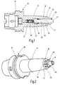
- Fig. 1
- einen schematischen axialen Längsschnitt eines Werkzeughalters mit darin eingespanntem Werkzeug,
- Fig. 2
- eine schematische perspektivische Ansicht des Werkzeughalters in Fig. 1.
Claims (10)
- Werkzeughalter zur Schrumpfbefestigung rotierender Werkzeuge (11) mit vorwiegend zylindrischen Schäften (12), mit einem Spannfutter (13), das einen Spannabschnitt (14) mit konischer Aufnahmebohrung (15) zur Aufnahme eines Einsatzes (30) darin aufweist, der eine zylindrische Innenbohrung (32) zur Aufnahme des Werkzeugschaftes (12) und eine konische Außenfläche (31) zur Aufnahme in der Aufnahmebohrung (15) des Spannabschnitts (14) aufweist,
dadurch gekennzeichnet, dass der Einsatz (30) derart gestaltet ist, dass nach dem axialen Einschieben des Einsatzes (30) in das heiße Spannfutter (13) eine Anlage des Einsatzes (30) an dem Spannfutter (13) und an dem zuvor eingesteckten Werkzeugschaft (12) erfolgt und beim Abkühlen des Spannfutters (13) der Werkzeugschaft (12) gespannt wird, wobei eine Überbrückung großer Durchmessertoleranzen bei maximalen Spannkräften ermöglicht ist. - Werkzeughalter nach Anspruch 1,
dadurch gekennzeichnet, dass der Einsatz (30) derart gestaltet ist, dass dieser kraftlos oder mit geringen axialen Kräften in die Aufnahmebohrung (15) des heißen Spannabschnitts (14) einschiebbar ist. - Werkzeughalter nach Anspruch 1 oder 2,
dadurch gekennzeichnet, dass der Kegelwinkel der konischen Außenfläche (31)des Einsatzes (30) genauso groß wie der Kegelwinkel der konischen Aufnahmebohrung (15) des Spannabschnitts (14) und dabei beide kleiner als der Selbsthemmungswinkel bemessen sind. - Werkzeughalter nach einem der Ansprüche 1 bis 3,
dadurch gekennzeichnet, dass im Spannfutter (13), vorzugsweise koaxial zu dessen Aufnahmebohrung (15), eine Einstellschraube (19) einstellbar gehalten ist, die einen Axialanschlag für ein einzusteckendes Werkzeug (11) bildet und/oder zum Herausdrücken eines zu entnehmenden Werkzeuges (11) aus dem erwärmten Spannfutter (13) dienen kann. - Werkzeughalter nach einem der Ansprüche 1 bis 4,
dadurch gekennzeichnet, dass der Einsatz (30) mindestens einen Längsschlitz (33) aufweist. - Werkzeughalter nach Anspruch 5,
dadurch gekennzeichnet, dass der mindestens eine Längsschlitz (33) zumindest an einem axialen Ende des Einsatzes (30) offen ist. - Werkzeughalter nach Anspruch 5 oder 6,
dadurch gekennzeichnet, dass der Einsatz (30) mehrere, z.B. sechs, in Umfangsrichtung in Abständen voneinander angeordnete Längsschlitze (33) aufweist, die in abwechselnder Folge am einen bzw. am gegenüberliegenden axialen Ende offen sind. - Verfahren zum Spannen eines Werkzeuges (11) in einem Spannfutter (13) mittels Schrumpfbefestigung, insbesondere nach Anspruch 1,
dadurch gekennzeichnet, dass ein mit einer konischen Außenfläche (31) versehener Einsatz (30) in eine passende konische Aufnahmebohrung (15) eines Spannabschnitts (14) des Spannfutters (13) eingesetzt wird, dass das zu spannende Werkzeug (11) mit seinem zylindrischen Schaft (12) in eine zylindrische Innenbohrung (32) des Einsatzes (30) eingesetzt wird, dass das Spannfutter (13) zumindest im Bereich des Spannabschnittes (14) zum Erreichen einer Wärmedehnung erwärmt wird und dass hiernach der Einsatz (30) in die Aufnahmebohrung (15) des Spannabschnitts (14) axial eingedrückt wird und hiernach das Spannfutter (13) zumindest im Bereich des Spannabschnittes (14) abgekühlt wird. - Verfahren nach Anspruch 8,
dadurch gekennzeichnet, dass nach dem Einsetzen des Einsatzes (30) eine im Spannfutter (13) gehaltene Einstellschraube (19) auf die gewünschte axiale Einstecktiefe des Werkzeuges (11), das axial daran anschlägt, eingestellt wird. - Verfahren nach Anspruch 8 oder 9,
dadurch gekennzeichnet, dass zur Entnahme des Werkzeugs (11) das Spannfutter (13) zumindest im Bereich des Spannabschnitts (14) zum Erreichen einer Wärmedehnung erwärmt wird und mittels der Einstellschraube (19) eine Axialkraft auf den Werkzeugschaft (12) zum Herausdrücken des Werkzeuges (11) aus dem erwärmten Spannfutter (13) ausgeübt wird.
Applications Claiming Priority (2)
| Application Number | Priority Date | Filing Date | Title |
|---|---|---|---|
| DE10357369 | 2003-12-09 | ||
| DE10357369A DE10357369A1 (de) | 2003-12-09 | 2003-12-09 | Werkzeughalter zur Schrumpfbefestigung rotierender Werkzeuge mit vorwiegend zylindrischen Schäften |
Publications (3)
| Publication Number | Publication Date |
|---|---|
| EP1541265A2 true EP1541265A2 (de) | 2005-06-15 |
| EP1541265A3 EP1541265A3 (de) | 2006-03-01 |
| EP1541265B1 EP1541265B1 (de) | 2008-07-30 |
Family
ID=34485262
Family Applications (1)
| Application Number | Title | Priority Date | Filing Date |
|---|---|---|---|
| EP04027950A Not-in-force EP1541265B1 (de) | 2003-12-09 | 2004-11-25 | Verfahren zur Schrumpfbefestigung rotierender Werkzeuge mit vorwiegend zylindrischen Schäften |
Country Status (6)
| Country | Link |
|---|---|
| US (1) | US7137185B2 (de) |
| EP (1) | EP1541265B1 (de) |
| JP (1) | JP4638720B2 (de) |
| AT (1) | ATE402775T1 (de) |
| DE (2) | DE10357369A1 (de) |
| ES (1) | ES2308090T3 (de) |
Cited By (4)
| Publication number | Priority date | Publication date | Assignee | Title |
|---|---|---|---|---|
| WO2008097171A1 (en) * | 2007-02-08 | 2008-08-14 | Seco Tools Ab | Shrink-fit tool with mechanical retention member, and method of mounting a tool to a toolholder |
| EP2033728A2 (de) | 2007-09-08 | 2009-03-11 | Bilz Werkzeugfabrik GmbH & Co. KG | Einrichtung zum Einstellen und Befestigen eines Werkzeuges in einer Aufnahme eines Werkzeugfutters, insbesondere durch Schrumpfbefestigung |
| CN104889438A (zh) * | 2015-05-30 | 2015-09-09 | 广西玉柴机器股份有限公司 | 一种自锁式胀套结构 |
| CN105666159A (zh) * | 2016-03-31 | 2016-06-15 | 泉州市华茂机械设备有限公司 | 支重轮侧盖加工翻转台 |
Families Citing this family (20)
| Publication number | Priority date | Publication date | Assignee | Title |
|---|---|---|---|---|
| DE10082740B4 (de) * | 1999-09-16 | 2007-05-24 | Rego-Fix Ag | Vorrichtung zum thermischen Einschrumpfen von Werkzeugen |
| DE10349245A1 (de) * | 2002-12-11 | 2004-07-01 | E. Zoller GmbH & Co. KG Einstell- und Messgeräte | Werkzeughaltevorrichtung, Haltevorrichtung, Verfahren zum Positionieren eines Werkzeugs und Verfahren zum Vermessen eines Werkzeugs |
| DE102004026635A1 (de) | 2004-06-01 | 2005-12-29 | Franz Haimer Maschinenbau Kg | Durchmesserausgleichsbuchse für einen Werkzeughalter |
| DE102004042770A1 (de) * | 2004-06-14 | 2005-12-29 | Franz Haimer Maschinenbau Kg | Werkzeughalter für ein Rotationswerkzeug |
| DE102005013483A1 (de) * | 2005-03-23 | 2006-09-28 | Franz Haimer Maschinenbau Kg | Werkzeughalter |
| DE202005014350U1 (de) * | 2005-09-09 | 2005-11-10 | Haimer Gmbh | Werkzeughalter zur Schrumpfbefestigung von Werkzeugen |
| DE102005043626A1 (de) * | 2005-09-13 | 2007-03-22 | Franz Haimer Maschinenbau Kg | Schwingungsarmer Werkzeughalter |
| US7278196B1 (en) * | 2006-04-29 | 2007-10-09 | Stojan Stojanovski | Interlocking tool holder |
| US7556461B2 (en) * | 2007-05-01 | 2009-07-07 | Chin-Chiu Chen | Thermal expansion knife adapter |
| US7959387B2 (en) * | 2007-10-03 | 2011-06-14 | Kennametal Inc. | Shrink fit sleeve for tool holder |
| DE102009040173A1 (de) * | 2009-03-17 | 2010-09-23 | Gühring Ohg | Stelleinrichtung für Schrumpffutter-Werkzeugaufnahme |
| US8747033B2 (en) * | 2009-09-02 | 2014-06-10 | Lockheed Martin Corporation | Through tool coolant adapter for drilling motor |
| WO2011112967A1 (en) * | 2010-03-11 | 2011-09-15 | Edison Welding Institute, Inc. | Ultrasonic machining module |
| JP5501052B2 (ja) * | 2010-03-24 | 2014-05-21 | キヤノン株式会社 | 通信装置、通信装置の制御方法、プログラム |
| KR101225790B1 (ko) * | 2010-03-30 | 2013-01-23 | 현대제철 주식회사 | 잔류응력 검증용 시편 |
| US8292150B2 (en) | 2010-11-02 | 2012-10-23 | Tyco Healthcare Group Lp | Adapter for powered surgical devices |
| CN103394998A (zh) * | 2013-07-24 | 2013-11-20 | 吴江市世华丝绸有限公司 | 一种弹性夹头固定装置 |
| CN104259884A (zh) * | 2014-09-16 | 2015-01-07 | 芜湖市华益阀门制造有限公司 | 一种内孔定位夹具用的定位筒 |
| US9764390B2 (en) * | 2015-09-04 | 2017-09-19 | Cumberland & Western Resources, Llc | Closed-loop metalworking system |
| CN112502786A (zh) * | 2020-09-23 | 2021-03-16 | 中国航发沈阳发动机研究所 | 一种刷式密封结构及其加工方法 |
Citations (5)
| Publication number | Priority date | Publication date | Assignee | Title |
|---|---|---|---|---|
| EP0618030A1 (de) * | 1993-03-30 | 1994-10-05 | Nt Tool Kabushikikaisha | Spannzangefutter mit Ölförderung und seiner Spannzange |
| DE19638808A1 (de) * | 1996-09-20 | 1998-03-26 | Fx Marquart Gmbh | Werkzeughalter zur Befestigung eines Werkzeuges an einer Werkzeugmaschine und Spannzange |
| US6315506B1 (en) * | 1997-08-11 | 2001-11-13 | Mst Corporation | Shrinkage fit type tool holder |
| JP2002120115A (ja) * | 2000-10-11 | 2002-04-23 | Mst Corporation | 工具ホルダ |
| JP2002283162A (ja) * | 2001-03-27 | 2002-10-03 | Mst Corporation | 焼き嵌め式工具ホルダー |
Family Cites Families (11)
| Publication number | Priority date | Publication date | Assignee | Title |
|---|---|---|---|---|
| US2778651A (en) * | 1954-03-26 | 1957-01-22 | Erickson Tool Co | Chuck stops for drills |
| GB1111593A (en) * | 1964-09-25 | 1968-05-01 | Nat Res Dev | Improvements in or relating to the securing of sleeves in cylinder bores |
| US3678632A (en) * | 1969-11-26 | 1972-07-25 | Kennametal Inc | Quill for machine tools |
| US5311654A (en) * | 1992-09-25 | 1994-05-17 | Cook Harold D | Tool holder system and method of making |
| JP3697371B2 (ja) * | 1999-09-07 | 2005-09-21 | 株式会社日研工作所 | エンドミルチャッキング構造 |
| US6280126B1 (en) * | 1999-09-23 | 2001-08-28 | Aesop, Inc. | Damped tool holder and method |
| JP4331837B2 (ja) * | 1999-10-12 | 2009-09-16 | エヌティーツール株式会社 | 工具チャック及び工具チャック加熱装置 |
| IL132526A (en) * | 1999-10-22 | 2003-06-24 | E T M Prec Tool Mfg Ltd | Cutting tool assembly |
| US6260858B1 (en) * | 2000-01-12 | 2001-07-17 | Induction Technologies | Insulated heat shrink tool holder |
| CA2420480A1 (en) * | 2000-09-01 | 2002-03-07 | George S. Taylor | System for presetting shrink-fit tools |
| DE10100719A1 (de) * | 2001-01-10 | 2002-07-11 | Bilz Werkzeugfabrik Gmbh & Co | Spannfutter zum Spannen von Werkzeugen durch Schrumpfsitz |
-
2003
- 2003-12-09 DE DE10357369A patent/DE10357369A1/de not_active Withdrawn
-
2004
- 2004-11-25 ES ES04027950T patent/ES2308090T3/es active Active
- 2004-11-25 AT AT04027950T patent/ATE402775T1/de active
- 2004-11-25 EP EP04027950A patent/EP1541265B1/de not_active Not-in-force
- 2004-11-25 DE DE502004007726T patent/DE502004007726D1/de active Active
- 2004-12-03 JP JP2004350541A patent/JP4638720B2/ja not_active Expired - Fee Related
- 2004-12-03 US US11/003,861 patent/US7137185B2/en not_active Expired - Fee Related
Patent Citations (5)
| Publication number | Priority date | Publication date | Assignee | Title |
|---|---|---|---|---|
| EP0618030A1 (de) * | 1993-03-30 | 1994-10-05 | Nt Tool Kabushikikaisha | Spannzangefutter mit Ölförderung und seiner Spannzange |
| DE19638808A1 (de) * | 1996-09-20 | 1998-03-26 | Fx Marquart Gmbh | Werkzeughalter zur Befestigung eines Werkzeuges an einer Werkzeugmaschine und Spannzange |
| US6315506B1 (en) * | 1997-08-11 | 2001-11-13 | Mst Corporation | Shrinkage fit type tool holder |
| JP2002120115A (ja) * | 2000-10-11 | 2002-04-23 | Mst Corporation | 工具ホルダ |
| JP2002283162A (ja) * | 2001-03-27 | 2002-10-03 | Mst Corporation | 焼き嵌め式工具ホルダー |
Non-Patent Citations (2)
| Title |
|---|
| PATENT ABSTRACTS OF JAPAN Bd. 2002, Nr. 08, 5. August 2002 (2002-08-05) & JP 2002 120115 A (MST CORPORATION), 23. April 2002 (2002-04-23) * |
| PATENT ABSTRACTS OF JAPAN Bd. 2003, Nr. 02, 5. Februar 2003 (2003-02-05) & JP 2002 283162 A (MST CORPORATION), 3. Oktober 2002 (2002-10-03) * |
Cited By (6)
| Publication number | Priority date | Publication date | Assignee | Title |
|---|---|---|---|---|
| WO2008097171A1 (en) * | 2007-02-08 | 2008-08-14 | Seco Tools Ab | Shrink-fit tool with mechanical retention member, and method of mounting a tool to a toolholder |
| US8656573B2 (en) | 2007-02-08 | 2014-02-25 | Seco Tools Ab | Shrink-fit tool with mechanical retention member, and method of mounting a tool to a toolholder |
| EP2033728A2 (de) | 2007-09-08 | 2009-03-11 | Bilz Werkzeugfabrik GmbH & Co. KG | Einrichtung zum Einstellen und Befestigen eines Werkzeuges in einer Aufnahme eines Werkzeugfutters, insbesondere durch Schrumpfbefestigung |
| DE102007042915A1 (de) | 2007-09-08 | 2009-03-12 | Bilz Werkzeugfabrik Gmbh & Co. Kg | Einrichtung zum Einstellen und Befestigen eines Werkzeuges in einer Aufnahme eines Werkzeugfutters, insbesondere durch Schrumpfbefestigung |
| CN104889438A (zh) * | 2015-05-30 | 2015-09-09 | 广西玉柴机器股份有限公司 | 一种自锁式胀套结构 |
| CN105666159A (zh) * | 2016-03-31 | 2016-06-15 | 泉州市华茂机械设备有限公司 | 支重轮侧盖加工翻转台 |
Also Published As
| Publication number | Publication date |
|---|---|
| EP1541265A3 (de) | 2006-03-01 |
| US20050135893A1 (en) | 2005-06-23 |
| JP4638720B2 (ja) | 2011-02-23 |
| US7137185B2 (en) | 2006-11-21 |
| ATE402775T1 (de) | 2008-08-15 |
| JP2005177980A (ja) | 2005-07-07 |
| DE502004007726D1 (de) | 2008-09-11 |
| DE10357369A1 (de) | 2005-07-07 |
| EP1541265B1 (de) | 2008-07-30 |
| ES2308090T3 (es) | 2008-12-01 |
Similar Documents
| Publication | Publication Date | Title |
|---|---|---|
| EP1541265B1 (de) | Verfahren zur Schrumpfbefestigung rotierender Werkzeuge mit vorwiegend zylindrischen Schäften | |
| DE2838348C2 (de) | Vorrichtung zum Ausformen einer Knochenöffnung | |
| DE4237582A1 (de) | Sperrkeilanordnung für zweiteilige, mechanisch verbundene Dorne | |
| EP2266732B1 (de) | Spannsystem | |
| DE102014016321B3 (de) | Spannsystem | |
| DE19923164C2 (de) | Spannfutter zum Spannen von Werkzeugen durch Schrumpfsitz | |
| DE19958832A1 (de) | Spannfutter zum Spannen von Werkzeugen durch Schrumpfsitz | |
| DE2708025A1 (de) | Einstellbarer werkzeughalter fuer eine bohrspindel | |
| DE4311936A1 (de) | Verfahren und Vorrichtung zum verschiebesicheren Positionieren eines Bauteils | |
| DE102013108999A1 (de) | Werkzeughalter für ein rotierendes Werkzeug | |
| DE4115992A1 (de) | Spannzange fuer werkzeuge | |
| DE1919439B2 (de) | Schnellspannfutter für einen Schaft aufweisende Werkzeuge | |
| DE202007013371U1 (de) | Werkzeugadapter | |
| DE2052037C3 (de) | Kraftbetätigtes Spannfutter mit mehreren radial geführten Spannbacken | |
| EP1322442A1 (de) | Wärmeschrumpffutter | |
| DE3413285A1 (de) | Spannvorrichtung fuer werkzeuge, wie bohrer, fraeser oder dgl. | |
| DE3802933A1 (de) | Verfahren und vorrichtung zur buerstbearbeitung einer oberflaeche | |
| EP1198320B1 (de) | Werkzeug | |
| DE2126621C3 (de) | Spann- und Lösevorrichtung für einen konischen Schaft aufweisende Werkzeuge | |
| EP1738846A1 (de) | Vorrichtung und Verfahren zum Lösen einer Nietverbindung | |
| DE102019109556A1 (de) | Verfahren zum Betrieb einer Fräseinrichtung sowie Set umfassend eine Mehrzahl von Fräseinrichtungen | |
| DE4440697C2 (de) | Spannfutter | |
| DE102007016490B4 (de) | Handhabungsvorrichtung | |
| DE1477294C (de) | Schneidwerkzeug fur die spanabhebende Bearbeitung | |
| DE2404441C3 (de) | Kompressionsnagel für Knochenbrüche und Werkzeuge zur Handhabung desselben |
Legal Events
| Date | Code | Title | Description |
|---|---|---|---|
| PUAI | Public reference made under article 153(3) epc to a published international application that has entered the european phase |
Free format text: ORIGINAL CODE: 0009012 |
|
| AK | Designated contracting states |
Kind code of ref document: A2 Designated state(s): AT BE BG CH CY CZ DE DK EE ES FI FR GB GR HU IE IS IT LI LU MC NL PL PT RO SE SI SK TR |
|
| AX | Request for extension of the european patent |
Extension state: AL HR LT LV MK YU |
|
| PUAL | Search report despatched |
Free format text: ORIGINAL CODE: 0009013 |
|
| AK | Designated contracting states |
Kind code of ref document: A3 Designated state(s): AT BE BG CH CY CZ DE DK EE ES FI FR GB GR HU IE IS IT LI LU MC NL PL PT RO SE SI SK TR |
|
| AX | Request for extension of the european patent |
Extension state: AL HR LT LV MK YU |
|
| 17P | Request for examination filed |
Effective date: 20060330 |
|
| 17Q | First examination report despatched |
Effective date: 20060801 |
|
| AKX | Designation fees paid |
Designated state(s): AT BE BG CH CY CZ DE DK EE ES FI FR GB GR HU IE IS IT LI LU MC NL PL PT RO SE SI SK TR |
|
| RTI1 | Title (correction) |
Free format text: PROCESS FOR THE SHRINK-FITTING OF ROTARY TOOLS WITH PREDOMINANTLY CYLINDRICAL SHAFTS |
|
| GRAP | Despatch of communication of intention to grant a patent |
Free format text: ORIGINAL CODE: EPIDOSNIGR1 |
|
| GRAS | Grant fee paid |
Free format text: ORIGINAL CODE: EPIDOSNIGR3 |
|
| GRAA | (expected) grant |
Free format text: ORIGINAL CODE: 0009210 |
|
| AK | Designated contracting states |
Kind code of ref document: B1 Designated state(s): AT BE BG CH CY CZ DE DK EE ES FI FR GB GR HU IE IS IT LI LU MC NL PL PT RO SE SI SK TR |
|
| REG | Reference to a national code |
Ref country code: GB Ref legal event code: FG4D Free format text: NOT ENGLISH |
|
| REG | Reference to a national code |
Ref country code: CH Ref legal event code: EP |
|
| REF | Corresponds to: |
Ref document number: 502004007726 Country of ref document: DE Date of ref document: 20080911 Kind code of ref document: P |
|
| REG | Reference to a national code |
Ref country code: IE Ref legal event code: FG4D Free format text: LANGUAGE OF EP DOCUMENT: GERMAN |
|
| REG | Reference to a national code |
Ref country code: SE Ref legal event code: TRGR |
|
| REG | Reference to a national code |
Ref country code: ES Ref legal event code: FG2A Ref document number: 2308090 Country of ref document: ES Kind code of ref document: T3 |
|
| PG25 | Lapsed in a contracting state [announced via postgrant information from national office to epo] |
Ref country code: PT Free format text: LAPSE BECAUSE OF FAILURE TO SUBMIT A TRANSLATION OF THE DESCRIPTION OR TO PAY THE FEE WITHIN THE PRESCRIBED TIME-LIMIT Effective date: 20081230 Ref country code: NL Free format text: LAPSE BECAUSE OF FAILURE TO SUBMIT A TRANSLATION OF THE DESCRIPTION OR TO PAY THE FEE WITHIN THE PRESCRIBED TIME-LIMIT Effective date: 20080730 Ref country code: IS Free format text: LAPSE BECAUSE OF FAILURE TO SUBMIT A TRANSLATION OF THE DESCRIPTION OR TO PAY THE FEE WITHIN THE PRESCRIBED TIME-LIMIT Effective date: 20081130 |
|
| PG25 | Lapsed in a contracting state [announced via postgrant information from national office to epo] |
Ref country code: FI Free format text: LAPSE BECAUSE OF FAILURE TO SUBMIT A TRANSLATION OF THE DESCRIPTION OR TO PAY THE FEE WITHIN THE PRESCRIBED TIME-LIMIT Effective date: 20080730 Ref country code: SI Free format text: LAPSE BECAUSE OF FAILURE TO SUBMIT A TRANSLATION OF THE DESCRIPTION OR TO PAY THE FEE WITHIN THE PRESCRIBED TIME-LIMIT Effective date: 20080730 Ref country code: BG Free format text: LAPSE BECAUSE OF FAILURE TO SUBMIT A TRANSLATION OF THE DESCRIPTION OR TO PAY THE FEE WITHIN THE PRESCRIBED TIME-LIMIT Effective date: 20081030 |
|
| REG | Reference to a national code |
Ref country code: IE Ref legal event code: FD4D |
|
| PG25 | Lapsed in a contracting state [announced via postgrant information from national office to epo] |
Ref country code: EE Free format text: LAPSE BECAUSE OF FAILURE TO SUBMIT A TRANSLATION OF THE DESCRIPTION OR TO PAY THE FEE WITHIN THE PRESCRIBED TIME-LIMIT Effective date: 20080730 Ref country code: DK Free format text: LAPSE BECAUSE OF FAILURE TO SUBMIT A TRANSLATION OF THE DESCRIPTION OR TO PAY THE FEE WITHIN THE PRESCRIBED TIME-LIMIT Effective date: 20080730 Ref country code: IE Free format text: LAPSE BECAUSE OF FAILURE TO SUBMIT A TRANSLATION OF THE DESCRIPTION OR TO PAY THE FEE WITHIN THE PRESCRIBED TIME-LIMIT Effective date: 20080730 |
|
| PG25 | Lapsed in a contracting state [announced via postgrant information from national office to epo] |
Ref country code: SK Free format text: LAPSE BECAUSE OF FAILURE TO SUBMIT A TRANSLATION OF THE DESCRIPTION OR TO PAY THE FEE WITHIN THE PRESCRIBED TIME-LIMIT Effective date: 20080730 Ref country code: RO Free format text: LAPSE BECAUSE OF FAILURE TO SUBMIT A TRANSLATION OF THE DESCRIPTION OR TO PAY THE FEE WITHIN THE PRESCRIBED TIME-LIMIT Effective date: 20080730 Ref country code: CZ Free format text: LAPSE BECAUSE OF FAILURE TO SUBMIT A TRANSLATION OF THE DESCRIPTION OR TO PAY THE FEE WITHIN THE PRESCRIBED TIME-LIMIT Effective date: 20080730 |
|
| BERE | Be: lapsed |
Owner name: BILZ WERKZEUGFABRIK G.M.B.H. & CO. KG Effective date: 20081130 |
|
| PLBE | No opposition filed within time limit |
Free format text: ORIGINAL CODE: 0009261 |
|
| STAA | Information on the status of an ep patent application or granted ep patent |
Free format text: STATUS: NO OPPOSITION FILED WITHIN TIME LIMIT |
|
| PG25 | Lapsed in a contracting state [announced via postgrant information from national office to epo] |
Ref country code: MC Free format text: LAPSE BECAUSE OF NON-PAYMENT OF DUE FEES Effective date: 20081130 |
|
| REG | Reference to a national code |
Ref country code: CH Ref legal event code: PL |
|
| 26N | No opposition filed |
Effective date: 20090506 |
|
| PG25 | Lapsed in a contracting state [announced via postgrant information from national office to epo] |
Ref country code: BE Free format text: LAPSE BECAUSE OF NON-PAYMENT OF DUE FEES Effective date: 20081130 |
|
| PG25 | Lapsed in a contracting state [announced via postgrant information from national office to epo] |
Ref country code: CH Free format text: LAPSE BECAUSE OF NON-PAYMENT OF DUE FEES Effective date: 20081130 Ref country code: LI Free format text: LAPSE BECAUSE OF NON-PAYMENT OF DUE FEES Effective date: 20081130 |
|
| PG25 | Lapsed in a contracting state [announced via postgrant information from national office to epo] |
Ref country code: PL Free format text: LAPSE BECAUSE OF FAILURE TO SUBMIT A TRANSLATION OF THE DESCRIPTION OR TO PAY THE FEE WITHIN THE PRESCRIBED TIME-LIMIT Effective date: 20080730 |
|
| PG25 | Lapsed in a contracting state [announced via postgrant information from national office to epo] |
Ref country code: HU Free format text: LAPSE BECAUSE OF FAILURE TO SUBMIT A TRANSLATION OF THE DESCRIPTION OR TO PAY THE FEE WITHIN THE PRESCRIBED TIME-LIMIT Effective date: 20090131 Ref country code: LU Free format text: LAPSE BECAUSE OF NON-PAYMENT OF DUE FEES Effective date: 20081125 Ref country code: CY Free format text: LAPSE BECAUSE OF FAILURE TO SUBMIT A TRANSLATION OF THE DESCRIPTION OR TO PAY THE FEE WITHIN THE PRESCRIBED TIME-LIMIT Effective date: 20080730 |
|
| PG25 | Lapsed in a contracting state [announced via postgrant information from national office to epo] |
Ref country code: TR Free format text: LAPSE BECAUSE OF FAILURE TO SUBMIT A TRANSLATION OF THE DESCRIPTION OR TO PAY THE FEE WITHIN THE PRESCRIBED TIME-LIMIT Effective date: 20080730 |
|
| PG25 | Lapsed in a contracting state [announced via postgrant information from national office to epo] |
Ref country code: GR Free format text: LAPSE BECAUSE OF FAILURE TO SUBMIT A TRANSLATION OF THE DESCRIPTION OR TO PAY THE FEE WITHIN THE PRESCRIBED TIME-LIMIT Effective date: 20081031 |
|
| REG | Reference to a national code |
Ref country code: DE Ref legal event code: R082 Ref document number: 502004007726 Country of ref document: DE Representative=s name: WITTE, WELLER & PARTNER, DE Ref country code: DE Ref legal event code: R082 Ref document number: 502004007726 Country of ref document: DE Representative=s name: WITTE, WELLER & PARTNER PATENTANWAELTE MBB, DE |
|
| PGFP | Annual fee paid to national office [announced via postgrant information from national office to epo] |
Ref country code: ES Payment date: 20141126 Year of fee payment: 11 Ref country code: SE Payment date: 20141119 Year of fee payment: 11 Ref country code: GB Payment date: 20141119 Year of fee payment: 11 Ref country code: FR Payment date: 20141119 Year of fee payment: 11 |
|
| PGFP | Annual fee paid to national office [announced via postgrant information from national office to epo] |
Ref country code: AT Payment date: 20141120 Year of fee payment: 11 |
|
| PGFP | Annual fee paid to national office [announced via postgrant information from national office to epo] |
Ref country code: IT Payment date: 20141128 Year of fee payment: 11 |
|
| REG | Reference to a national code |
Ref country code: AT Ref legal event code: MM01 Ref document number: 402775 Country of ref document: AT Kind code of ref document: T Effective date: 20151125 |
|
| GBPC | Gb: european patent ceased through non-payment of renewal fee |
Effective date: 20151125 |
|
| PG25 | Lapsed in a contracting state [announced via postgrant information from national office to epo] |
Ref country code: IT Free format text: LAPSE BECAUSE OF NON-PAYMENT OF DUE FEES Effective date: 20151125 |
|
| REG | Reference to a national code |
Ref country code: FR Ref legal event code: ST Effective date: 20160729 |
|
| PG25 | Lapsed in a contracting state [announced via postgrant information from national office to epo] |
Ref country code: SE Free format text: LAPSE BECAUSE OF NON-PAYMENT OF DUE FEES Effective date: 20151126 Ref country code: AT Free format text: LAPSE BECAUSE OF NON-PAYMENT OF DUE FEES Effective date: 20151125 |
|
| PG25 | Lapsed in a contracting state [announced via postgrant information from national office to epo] |
Ref country code: GB Free format text: LAPSE BECAUSE OF NON-PAYMENT OF DUE FEES Effective date: 20151125 |
|
| PG25 | Lapsed in a contracting state [announced via postgrant information from national office to epo] |
Ref country code: FR Free format text: LAPSE BECAUSE OF NON-PAYMENT OF DUE FEES Effective date: 20151130 |
|
| REG | Reference to a national code |
Ref country code: ES Ref legal event code: FD2A Effective date: 20170102 |
|
| PG25 | Lapsed in a contracting state [announced via postgrant information from national office to epo] |
Ref country code: ES Free format text: LAPSE BECAUSE OF NON-PAYMENT OF DUE FEES Effective date: 20151126 |
|
| PGFP | Annual fee paid to national office [announced via postgrant information from national office to epo] |
Ref country code: DE Payment date: 20191227 Year of fee payment: 16 |
|
| REG | Reference to a national code |
Ref country code: DE Ref legal event code: R119 Ref document number: 502004007726 Country of ref document: DE |
|
| PG25 | Lapsed in a contracting state [announced via postgrant information from national office to epo] |
Ref country code: DE Free format text: LAPSE BECAUSE OF NON-PAYMENT OF DUE FEES Effective date: 20210601 |