EP1541069A1 - Bouilloire - Google Patents
Bouilloire Download PDFInfo
- Publication number
- EP1541069A1 EP1541069A1 EP04026006A EP04026006A EP1541069A1 EP 1541069 A1 EP1541069 A1 EP 1541069A1 EP 04026006 A EP04026006 A EP 04026006A EP 04026006 A EP04026006 A EP 04026006A EP 1541069 A1 EP1541069 A1 EP 1541069A1
- Authority
- EP
- European Patent Office
- Prior art keywords
- container
- handle
- plate
- support plate
- kettle according
- Prior art date
- Legal status (The legal status is an assumption and is not a legal conclusion. Google has not performed a legal analysis and makes no representation as to the accuracy of the status listed.)
- Granted
Links
- XLYOFNOQVPJJNP-UHFFFAOYSA-N water Substances O XLYOFNOQVPJJNP-UHFFFAOYSA-N 0.000 title claims abstract description 20
- 229910052751 metal Inorganic materials 0.000 claims abstract description 26
- 239000002184 metal Substances 0.000 claims abstract description 25
- 239000004033 plastic Substances 0.000 claims abstract description 19
- 238000010438 heat treatment Methods 0.000 claims abstract description 9
- 229910001220 stainless steel Inorganic materials 0.000 claims description 6
- 239000010935 stainless steel Substances 0.000 claims description 6
- 239000008236 heating water Substances 0.000 claims description 2
- 238000005485 electric heating Methods 0.000 claims 1
- 230000000149 penetrating effect Effects 0.000 claims 1
- 229910000831 Steel Inorganic materials 0.000 abstract description 4
- 239000010959 steel Substances 0.000 abstract description 4
- 238000000034 method Methods 0.000 description 7
- 230000008569 process Effects 0.000 description 7
- 238000003466 welding Methods 0.000 description 7
- 230000008901 benefit Effects 0.000 description 6
- 238000007789 sealing Methods 0.000 description 6
- 238000002347 injection Methods 0.000 description 4
- 239000007924 injection Substances 0.000 description 4
- 230000006378 damage Effects 0.000 description 3
- 238000003860 storage Methods 0.000 description 3
- 230000000903 blocking effect Effects 0.000 description 2
- 238000009835 boiling Methods 0.000 description 2
- 230000008878 coupling Effects 0.000 description 2
- 238000010168 coupling process Methods 0.000 description 2
- 238000005859 coupling reaction Methods 0.000 description 2
- 230000000694 effects Effects 0.000 description 2
- 210000000887 face Anatomy 0.000 description 2
- 238000004519 manufacturing process Methods 0.000 description 2
- 239000000463 material Substances 0.000 description 2
- 239000002991 molded plastic Substances 0.000 description 2
- 230000035882 stress Effects 0.000 description 2
- 239000000725 suspension Substances 0.000 description 2
- 230000008646 thermal stress Effects 0.000 description 2
- 230000002411 adverse Effects 0.000 description 1
- 229910052782 aluminium Inorganic materials 0.000 description 1
- XAGFODPZIPBFFR-UHFFFAOYSA-N aluminium Chemical compound [Al] XAGFODPZIPBFFR-UHFFFAOYSA-N 0.000 description 1
- 230000004888 barrier function Effects 0.000 description 1
- 230000009286 beneficial effect Effects 0.000 description 1
- 230000008859 change Effects 0.000 description 1
- 230000006835 compression Effects 0.000 description 1
- 238000007906 compression Methods 0.000 description 1
- 238000009792 diffusion process Methods 0.000 description 1
- 238000006073 displacement reaction Methods 0.000 description 1
- 238000009413 insulation Methods 0.000 description 1
- 230000010354 integration Effects 0.000 description 1
- 238000012544 monitoring process Methods 0.000 description 1
- 238000000465 moulding Methods 0.000 description 1
- 229920000642 polymer Polymers 0.000 description 1
- 238000004080 punching Methods 0.000 description 1
- 238000010079 rubber tapping Methods 0.000 description 1
- 239000000243 solution Substances 0.000 description 1
- 125000006850 spacer group Chemical group 0.000 description 1
- 238000003892 spreading Methods 0.000 description 1
- 230000007480 spreading Effects 0.000 description 1
Images


Classifications
-
- A—HUMAN NECESSITIES
- A47—FURNITURE; DOMESTIC ARTICLES OR APPLIANCES; COFFEE MILLS; SPICE MILLS; SUCTION CLEANERS IN GENERAL
- A47J—KITCHEN EQUIPMENT; COFFEE MILLS; SPICE MILLS; APPARATUS FOR MAKING BEVERAGES
- A47J27/00—Cooking-vessels
- A47J27/21—Water-boiling vessels, e.g. kettles
- A47J27/21008—Water-boiling vessels, e.g. kettles electrically heated
- A47J27/21041—Water-boiling vessels, e.g. kettles electrically heated with heating elements arranged outside the water vessel
Definitions
- the inventions relate to an electric kettle for heating water according to the preambles of claims 1 and 8.
- the container is made of plastic.
- the bottom of the Plastic container is provided with a heating plate, at the bottom of the thermostatic device is attached.
- On the lateral surface of the plastic container fastening means and bearings are formed, where both the plastic Lid and the unlock button and the on or off button pivotally mounted are.
- Also from the opening of the kettle to the thermoswitch down leading steam channel is part of the lateral surface of the plastic container, i. also the Steam channel is formed during the injection process of the container with.
- the container in the upper region on two journals, where the Main part of the handle hung with its bearing eyes and attached via studs is.
- the main part In the lower area, the main part is screwed to the container wall.
- For screwing the container wall is extended beyond the floor down so far that there Screws can penetrate into the container wall without water leaking.
- the object of the invention is to improve a kettle according to the preamble in such a way that this shatterproof and more resistant to hot water and high quality Is provided. He should also be easy to assemble. Furthermore, the Thermal stresses occurring during heating of the boiler without consequential damage of the kettle can be collected. Finally, a kettle arise whose production is inexpensive despite high quality equipment.
- a carrier plate made of plastic which is attached to the metal container and as storage and receiving part for both the lid as used for the button or other controls. Since the integration of switching display elements, and the inclusion of the lid to a complex structure of a Metal container would lead, according to the invention, this support plate is provided. Namely, such a carrier plate can be easily in one or more injection operations ausformen and they can therefore from a particularly complex, nested component. exist without significantly increasing the cost of constructing the component.
- the inventive Carrier plate also has the advantage that before mounting the button, the unlock button as well as all related components and more Operating elements, if necessary, can be pre-assembled in the carrier plate and only then mounted on the container wall. The lid can then be stored in its storage at the Carrier plate are introduced.
- the kettle also has a release button as a further control element on, which serves to open the lid only when the heater is turned off is, it may according to a development of the invention according to claim 3 also be stored and pre-assembled in the carrier plate.
- the one described there Safety device consisting of blocking element, actuating element, button, Push rod, cover, compression spring, are also in the kettle according to the invention Components, but here they are not on the container of the container, but on the support plate attached, are provided on the separate recordings for this purpose. Equipment and Functioning can thus be used directly on the disclosure of this WO become, which is thus also part of this application.
- the fastening device from a welded to the outer surface of the metal container holding plate formed, having attachment means to which the carrier plate is attached.
- attachment means to which the carrier plate is attached.
- This holding plate Namely, can be punched out previously in a punching operation, bent accordingly and, where appropriate be provided with grub screws or threaded eyes. Such a process is fast and relatively inexpensive feasible. Only then is this holding plate in welded to the surface of the container made of metal in a single operation, preferably in the spot welding process.
- this holding plate a small distance from the surface has the container and thus serves as a thermal barrier, so not too much heat in the parts made of plastic, such as the support plate and the handle and the Cover, can penetrate.
- spacer ribs are integrally formed on the holding plate, the - except at the welding points - keep the sheet at a distance from the outer surface of the container.
- the handle a along the lateral surface of the container extending mounting flange, on the inside of which are fixed to edges metal strips, which engage in the retaining plate arrive when the handle is attached.
- the one-piece are molded with the handle made of plastic, but these could be on exposure melt or break under temperature over a long period of time, resulting in loosening of the Handle could lead from the metal container. This could then have devastating consequences when the kettle falls to the floor with boiling water and boiling water splashing around.
- each a metal strip with resilient Hook attached which expand elastically when assembled and then the edge behind the retaining plate captive.
- the metal strips are in the injection mold, the forms the handle, inserted and are so partially encapsulated positively. It is but also quite possible, after the injection process of the handle on the retaining plates apply the edges of the handle and then formed by means of the handle nose to heat them so that they partially embrace the retaining plate, similar a riveting process.
- the handle also attached to the retaining plate, here other attachment points than in the Attachment of the carrier plate can be used.
- This has the decisive advantage that at acting heat both on the retaining plate as on the handle, these parts are not mutually as a result of the onset of thermal stress occurring expansion adversely affect. This is especially important if a long mechanical Link, namely a push rod, between the switch button and the Thermal switch is present, the switching even with the slightest shifts triggers because provided on the thermostatic switch gears in very tight tolerances are held.
- the handle during its heating through the steel container independently of the support plate over the edge of the retaining plate can move either up or down because the hooks are longitudinal on the edge, which here assumes the function of a rail, slide back and forth can.
- stresses due to temperature on the Handle avoided.
- the support plate is thus firmly clamped in the middle of the holding plate and can to expand both vertically upwards and downwards as heat is applied across the middle.
- the hooks when mounting the handle is not radial to expand outward, but the hook and the edge in such a way that the Handle - similar to a sliding gate - on the edge of the one side pushed out while the two opposing hook loads cross the edge without clearance. or behind.
- the opening facing The area of the handle is fixed to the container stationary, so forms the fixed bearing, while in length expansion, the other end can expand towards the ground.
- the handle can not bend and it always remains its edge flush with the lateral surface of the container to the plant, so that no dirt from the outside in the Deepening and the support plate can penetrate.
- the Edge of the mounting flange of the handle so elastically formed that he always tight abuts the lateral surface.
- the distance between the opposite Edges on the mounting plate so accurately measured and tolerated which of course also to vote for the distances of the opposite hooks on the metal strips on the handle got to.
- This is therefore necessary that without too much contact pressure of the handle on Bracket mounted by spreading the hooks and then engaging behind the edges can be.
- these areas of wells formed which are slightly larger in their longitudinal direction than the length of the latching hook, so must only these areas are calibrated to a minimum, which reduces manufacturing costs.
- the areas must be longer than the length of the hooks, so that when expanding as a result of the effect of temperature, the hooks in these areas can move back and forth.
- the studs are from above the handle in introduced the holes of the bearing eyes and journals when the holes to each other aligned. If you do not want to see the attachment points of the handle from the outside, so you have the handle according to the features of claim 12 in the upper area in two parts, which is done by an open-topped handle, which subsequently Closing of the main part is covered by the back part from above. simultaneously is also the whole upper part of the support part, in which the reset button, the button and the lid is stored, covered from above and is thus captive on the support plate attached.
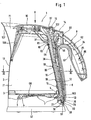
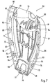
- the electrically operated kettle 1 consists of one Metal, preferably made of stainless steel, manufactured container 2, the substantially is tubular. At the filling or pouring opening 71 is a spout 107 formed for pouring or pouring water. Behind the spout 107 is located a sieve 108.
- thermostat switch 7 (only partially indicated) is electrically conductively connected.
- the electric thermostat switch 7 is via a lever (not shown) and a rocker 6 mechanically with a bent over a joint 13 Connecting rod 8 connected.
- the push rod 8 extends laterally on the container in Fig. 1 above, where it is mechanically connected to a switch button 14.
- a handle 9 On the lateral surface 12 of the container 2 is at the height of a handle 9, which is mounted later and is explained in more detail, formed from a bottom-up widening recess 17, in a corresponding to the recess 17 adapted retaining plate 18 preferably in Spot welding is attached, as illustrated in particular Fig. 5.
- Figures 1 and 5 are on the inner wall of the container 2 horizontally extending ribs 95th out, engage in the outside of the retaining plate 18 correspondingly extending ribs 96.
- the rib 97 on the retaining plate 18 is substantially U-shaped.
- the ribs 95, 96,97 serve that during the spot welding process the holding plate 18 centered about its ribs 96, 97 in the ribs 95 can be, which simplifies the mounting of the holding plate 18 on the container 2.
- Both that Holding plate 18 as the container 2 consist of one in several operations from a Blank drawn molding.
- Fig. 5 are in the recess 17 in the lower and upper region on both sides of a Longitudinal axis 22 holes 19, 20 are mounted, which connect the container interior 21 to the outside.
- the recess 17 and the retaining plate 18 are symmetrical to the longitudinal axis 22, the vertical and slightly to the container 2 upwards in the direction of the spout or Fill opening 71 is inclined, formed.
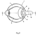
- the central axis 110 (FIG. 2) of the handle 9 also runs symmetrically to this longitudinal axis 22.
- Fig. 5 are still between the bores 19 and 20 arranged symmetrically to the longitudinal axis 22 at a distance one above the other Threaded eyes 23, 24, 25 bulged outward bulging formed.
- an opening 29 is formed, as shown in FIG. 5.
- FIG. 5 in the recess 17 is still symmetrical to the longitudinal axis 22 trained incision 30 disposed from the lateral edges 100 itself formed from sheet metal angle plates 32 raise, at its superposed tabs 99 mutually aligned and arranged vertically upwardly extending bores 31 are, as can be seen in particular from Figures 4 and 5.
- the holding plate 18 further points to the figures 4 and 5 on both sides of the longitudinal axis 22 from below above an edge 33 which is substantially parallel and spaced from the outer edge 101 of the recess 17 extends from bottom to top.
- Fig. 4 is about screws 26, 27, in the threaded eyes 23, 24 am Holding plate 18 engage, a support plate 10 on the support plate 18 and thus on the container 2 attached.
- the support plate 10 is again for clarity in Fig. 6 as a single part shown. It can be seen that for fixing the support plate 10 in this has lower and upper area bores 34, 35, wherein the lower holes 34 in the Cross-section round and the upper holes 35 in cross-section stretched upward oval are formed. This is so, because of the temperature at resulting different length change of the container made of stainless steel 2 and the carrier plate 10 made of plastic, these only upwards can extend.
- the lower screws 27 are screwed relatively firmly, while the upper screws 26 are only screwed so tightly that a relative displacement the support plate 10 is possible upwards, but still the support plate 10 always still firmly attached to the retaining plate 18 remains.
- the thermal expansion of plastic is in fact about 6 to 7 times larger than stainless steel, so that to stress on the components to avoid having to stretch without damage.
- the carrier plate 10 faces outward a bottom upwardly extending guide groove 11 which is adapted to receive a closed, serves in cross-section substantially quadrangular steam channel 36, at its upper end 102 via the formed on the support plate 10 opening 37 in the below the lid 15 formed container space 21 protrudes and its free open lower end for the purpose of temperature control to the vicinity of a bimetal (not shown) comes close, which is part of the thermal switch 7 (Fig. 1).
- the steam channel 36 is after Fig. 4 attached via side tabs 38 in the lower and upper region with the support plate 10.
- the support plate 10 has longitudinal grooves 70 and slots 39 for pivotable receiving the lid 15 and the release button 16.
- the carrier plate 10 is also formed symmetrically to the longitudinal axis 22 of the guide groove 11, that is, the holes 34, 35, the slots 39, the bearing arms 40 and the openings 41 are arranged symmetrically to the carrier plate 10.
- a leaf spring 45 is attached to the support plate 10, a Locking lever 46 resiliently presses against the switch button 14.
- the locking lever 46 is over axes 47 stored in bearing blocks 48 of the support plate 10.
- the leaf spring 45 as the locking lever 46 are arranged symmetrically to the longitudinal axis 22 of the support plate 10.
- the material of the sealing rings 44 must be so voluminous and elastic, that no leakage occurs during thermal expansion.
- hinge pins 52 used in the main part 53 of the handle 9 formed on projections 54 holes 55 engage see also Fig. 7.
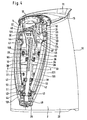
- the main part 53 of the handle 9 is shown in perspective in Fig. 7 from the inside and has a formed from bottom to top, trained as strips mounting flange 56 on both sides, between the upper end, the lower half as a half-shell of the actual handle arm lower part 57 extends away, the one-piece with the mounting flange 56 is formed as a plastic part.
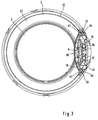
- On the two insides of the facing edges 58 are attached from bottom to top extending metal strips 59, to which bent out at substantially rectangular recesses 60 resilient hook 61 are, as this particular Fig. 3 shows.
- the metal strips 59 have over the length superimposed holes 73 which integrally formed on the main part 53 Pegs 74 are penetrated.
- the pins 74 are deformed by thermal plastic deformation such that - similar to a rivet - press the metal strip 59 against the main part 53.
- the assembly of the support plate 10, the controls 14, 16, the leaf spring 45, the Locking lever 46, the lid 15, the water level indicator 42, the push rod 8, the Rocker 6 and the main part 53 with its back part 62 is the following:
- the steam channel 36 is mounted on the support plate 10 in the guide groove 11, by his tabs 38 with the support plate 10 by means of latching hooks 63 which are connected to the Tabs 38 formed holes 64 engage behind, as indicated in FIG. 4.
- the Support plate 10 via a at the upper end downwardly open groove 81 from above the edge 82 (Fig. 5) of the incision 30 mounted.
- the support plate 10th As shown in FIG. 4 attached to the holding plate 18 and the screws 27 initially in the lower Area screwed to the container 2.
- the upper screws 26th inserted into the slots 35 and bolted to the threaded eyes 23.
- the screws 27, 26 may be, for example, self-tapping screws when screwing in the thread eyes 25, 23 there in the holes 67, 68 cut thread. But it is also conceivable, in the holes 67, 68 previously threaded by means of a tap cut and then preferably to use screws 27, 26 with metric thread. This would have the advantage that higher torques applied during screwing can be and thus a particularly strong connection exists. But it could be too previously 18 threaded sleeves are welded to the back of the retaining plate, so that longer threads are created.
- the support plate 10 is not only by the screws 26, 27 held on the container 2, but also in the upper area by the Groove 81.
- the leaf spring 45 is still attached to FIG. 4, by their to the free Leg ends trained bores 66 protruding on the support plate 10 Pins 65 are pushed and then their free ends 105 such means Heat are plastically deformed that they - similar to a rivet - the leaf spring 45 firmly hold the carrier plate 10. The other end 106 is thus elastically deformed outwards, that it presses resiliently against the blocking element 46.
- the main part 53 is formed with its projections 54 in the angle plates 32, quadrangular recordings 72 used (not shown) and is thus first in held and centered at the top. Subsequently, the main part 53 with its protruding Hook 61 so firmly pressed against the edges 33 of the holding plate 18 that the Snap hook 61 deform plastically outward, jump over the edge 33 and the Surround edge 33 of the jacket surface 12 of the container 2 facing side (Fig. 1).
- Fig. 1 is at the lower portion of the main part 53 at this an extension 76 with a Bore 77 is formed, which penetrates a screw 78 (Fig. 1) and the one in the lower Edge of the opening 29 screwed to a sheet metal tab 79 formed hole 80 is and so also the support plate 10 pulls down to the container 2 and holds stationary there.
- the release button 16, the switch button 14 and the lid 15 is not up the recess 75 can be removed, and thus at the same time the main part 53 of is closed at the top, is still the main part 53 from above closing Back portion 84 with the main part 53 over along the back portion 84 extending Locking lugs 85, which pass through correspondingly adapted holes 86, clipped.
- the unlock button 16 and the switch button 14 protrude over on the back 84th formed openings 87, 88 outwardly and are so by hand to operate accessible (Fig. 1).
- the container 2 from below an opening 89, preferably at the edge thereof diametrically opposite two part-circular recesses 90 are formed are. These recesses 90 serve to receive not shown in the drawing Display elements in the form of luminaires, which then light up when the kettle 1 is turned on.
- the display elements are part of a used in the opening 89
- Bottom part 91 (Fig. 1), via screws (not shown) with the housing of the thermostat switch 7 is connected.
- a power coupling (not shown) arranged on the touchdown on a corresponding power coupling having base 92 and when the device is powered, the heater 4 with power becomes.
Landscapes
- Engineering & Computer Science (AREA)
- Food Science & Technology (AREA)
- Cookers (AREA)
- Details Of Rigid Or Semi-Rigid Containers (AREA)
- Iron Core Of Rotating Electric Machines (AREA)
Applications Claiming Priority (2)
| Application Number | Priority Date | Filing Date | Title |
|---|---|---|---|
| DE10357965 | 2003-12-11 | ||
| DE10357965A DE10357965B3 (de) | 2003-12-11 | 2003-12-11 | Wasserkessel |
Publications (2)
| Publication Number | Publication Date |
|---|---|
| EP1541069A1 true EP1541069A1 (fr) | 2005-06-15 |
| EP1541069B1 EP1541069B1 (fr) | 2006-08-16 |
Family
ID=34089311
Family Applications (1)
| Application Number | Title | Priority Date | Filing Date |
|---|---|---|---|
| EP04026006A Expired - Lifetime EP1541069B1 (fr) | 2003-12-11 | 2004-11-03 | Bouilloire |
Country Status (5)
| Country | Link |
|---|---|
| EP (1) | EP1541069B1 (fr) |
| CN (1) | CN100528046C (fr) |
| AT (1) | ATE336193T1 (fr) |
| DE (2) | DE10357965B3 (fr) |
| RU (1) | RU2284140C2 (fr) |
Cited By (2)
| Publication number | Priority date | Publication date | Assignee | Title |
|---|---|---|---|---|
| JP2010069017A (ja) * | 2008-09-18 | 2010-04-02 | Zojirushi Corp | 電気ケトル |
| CN106264101A (zh) * | 2015-05-11 | 2017-01-04 | 广东美的生活电器制造有限公司 | 电热水杯 |
Families Citing this family (5)
| Publication number | Priority date | Publication date | Assignee | Title |
|---|---|---|---|---|
| CN101469907B (zh) * | 2007-12-29 | 2011-08-17 | 博西华电器(江苏)有限公司 | 家用电器 |
| DE202010004253U1 (de) * | 2010-03-26 | 2010-06-10 | SEVERIN ELEKTROGERÄTE GmbH | Elektrischer Wasserkocher |
| RU2531888C1 (ru) * | 2013-10-08 | 2014-10-27 | Федеральное государственное бюджетное образовательное учреждение высшего профессионального образования "Казанский государственный энергетический университет" (ФГБОУ ВПО "КГЭУ") | Электрический чайник |
| FR3055786B1 (fr) * | 2016-09-13 | 2018-09-07 | Seb S.A. | Bouilloire compacte munie d'une paroi inclinee |
| US20250107651A1 (en) * | 2023-09-29 | 2025-04-03 | Christian Gibbs Kendall | Musical Tea Kettle with Improved Safety Features |
Citations (4)
| Publication number | Priority date | Publication date | Assignee | Title |
|---|---|---|---|---|
| DE29603838U1 (de) * | 1996-03-01 | 1996-04-25 | Petra-Electric Peter Hohlfeldt GmbH & Co, 89331 Burgau | Wasserkocher |
| GB2337194A (en) * | 1998-05-13 | 1999-11-17 | Otter Controls Ltd | Electric kettle with water level indicator |
| DE19860931A1 (de) * | 1998-12-30 | 2000-07-06 | Efbe Elektrogeraete Gmbh | Wasserkocher mit Sicherheitsabschaltung |
| WO2001001830A1 (fr) * | 1999-06-30 | 2001-01-11 | Robert Mark Brett Coulton | Bouilloire |
Family Cites Families (4)
| Publication number | Priority date | Publication date | Assignee | Title |
|---|---|---|---|---|
| GB1355499A (en) * | 1970-07-29 | 1974-06-05 | Bulpitt Sons Ltd | Kettles |
| GB1471641A (en) * | 1975-10-30 | 1977-04-27 | Bulpitt Sons Ltd | Electric kettles |
| SU1629229A1 (ru) * | 1988-08-04 | 1991-02-23 | Всесоюзный Научно-Исследовательский Институт Цементного Машиностроения | Грузонесущий орган конвейера |
| DE19905641A1 (de) * | 1999-02-11 | 2000-08-31 | Braun Gmbh | Elektrisch beheizbarer Wasserkocher |
-
2003
- 2003-12-11 DE DE10357965A patent/DE10357965B3/de not_active Expired - Fee Related
-
2004
- 2004-11-03 DE DE502004001193T patent/DE502004001193D1/de not_active Expired - Lifetime
- 2004-11-03 AT AT04026006T patent/ATE336193T1/de active
- 2004-11-03 EP EP04026006A patent/EP1541069B1/fr not_active Expired - Lifetime
- 2004-12-01 RU RU2004135015/12A patent/RU2284140C2/ru active
- 2004-12-10 CN CNB2004101000931A patent/CN100528046C/zh not_active Expired - Fee Related
Patent Citations (4)
| Publication number | Priority date | Publication date | Assignee | Title |
|---|---|---|---|---|
| DE29603838U1 (de) * | 1996-03-01 | 1996-04-25 | Petra-Electric Peter Hohlfeldt GmbH & Co, 89331 Burgau | Wasserkocher |
| GB2337194A (en) * | 1998-05-13 | 1999-11-17 | Otter Controls Ltd | Electric kettle with water level indicator |
| DE19860931A1 (de) * | 1998-12-30 | 2000-07-06 | Efbe Elektrogeraete Gmbh | Wasserkocher mit Sicherheitsabschaltung |
| WO2001001830A1 (fr) * | 1999-06-30 | 2001-01-11 | Robert Mark Brett Coulton | Bouilloire |
Cited By (3)
| Publication number | Priority date | Publication date | Assignee | Title |
|---|---|---|---|---|
| JP2010069017A (ja) * | 2008-09-18 | 2010-04-02 | Zojirushi Corp | 電気ケトル |
| CN106264101A (zh) * | 2015-05-11 | 2017-01-04 | 广东美的生活电器制造有限公司 | 电热水杯 |
| CN106264101B (zh) * | 2015-05-11 | 2017-12-22 | 广东美的生活电器制造有限公司 | 电热水杯 |
Also Published As
| Publication number | Publication date |
|---|---|
| CN100528046C (zh) | 2009-08-19 |
| ATE336193T1 (de) | 2006-09-15 |
| RU2284140C2 (ru) | 2006-09-27 |
| CN1653992A (zh) | 2005-08-17 |
| DE10357965B3 (de) | 2005-02-24 |
| DE502004001193D1 (de) | 2006-09-28 |
| RU2004135015A (ru) | 2006-05-20 |
| EP1541069B1 (fr) | 2006-08-16 |
Similar Documents
| Publication | Publication Date | Title |
|---|---|---|
| DE102005018597B3 (de) | Heizsystem mit Temperatursicherungseinrichtungen und Wärmeübertragungselement hierfür | |
| DE69700974T2 (de) | Elektrischer Kessel mit heizender metallischer Platte | |
| DE3524651A1 (de) | Befestigungsclip | |
| DE2620004A1 (de) | Elektrokochplatte mit einem temperaturbegrenzer | |
| EP2637474A1 (fr) | Elément chauffant | |
| DE3335934C2 (fr) | ||
| DE2509158C3 (de) | Elektrische Klemme | |
| EP0100861B1 (fr) | Réchaud électrique comportant un disjoncteur de protection de température | |
| EP1541069B1 (fr) | Bouilloire | |
| EP0962951A2 (fr) | Interrupteur thermique, en particulier régulateur de température réglable | |
| DE1490739B1 (de) | Verfahren zum Einstellen der Betaetigungsbewegung eines Thermoschnappgliedes | |
| DE112015004768T5 (de) | Temperaturschalter | |
| DE3233909A1 (de) | Schnappvorrichtung, insbesondere elektrischer schnappschalter | |
| DE2828052A1 (de) | Schnaepperscharnier | |
| DE2452543A1 (de) | Thermostatbefestigung fuer geschirrspueler | |
| DE1924701B2 (de) | Vorrichtung zur Betätigung eines Schalters mit einem zwei in Abstand voneinander befindliche Schenkel aufweisenden Bimetallblech | |
| DE102023102302B3 (de) | Temperaturabhängiger Schalter | |
| DE2414812A1 (de) | Ausdehnungsdose fuer temperaturempfindliche systeme | |
| DE3587064T2 (de) | Thermostat. | |
| AT350302B (de) | Vorrichtung zur befestigung thermischer schalter | |
| CH690132A5 (de) | Entwässerungsrinne. | |
| EP1731850B1 (fr) | Chaudière en matière plastique sans bride | |
| DE102009032385B3 (de) | Beheizbarer Wasserkessel mit einem eine Deckelöffnung aufweisenden Deckel | |
| EP1850712B1 (fr) | Bouilloire electrique | |
| EP1044642A1 (fr) | Récipient de cuisson |
Legal Events
| Date | Code | Title | Description |
|---|---|---|---|
| PUAI | Public reference made under article 153(3) epc to a published international application that has entered the european phase |
Free format text: ORIGINAL CODE: 0009012 |
|
| AK | Designated contracting states |
Kind code of ref document: A1 Designated state(s): AT BE BG CH CY CZ DE DK EE ES FI FR GB GR HU IE IS IT LI LU MC NL PL PT RO SE SI SK TR |
|
| AX | Request for extension of the european patent |
Extension state: AL HR LT LV MK YU |
|
| 17P | Request for examination filed |
Effective date: 20050630 |
|
| AKX | Designation fees paid |
Designated state(s): AT BE BG CH CY CZ DE DK EE ES FI FR GB GR HU IE IS IT LI LU MC NL PL PT RO SE SI SK TR |
|
| GRAP | Despatch of communication of intention to grant a patent |
Free format text: ORIGINAL CODE: EPIDOSNIGR1 |
|
| GRAS | Grant fee paid |
Free format text: ORIGINAL CODE: EPIDOSNIGR3 |
|
| GRAA | (expected) grant |
Free format text: ORIGINAL CODE: 0009210 |
|
| AK | Designated contracting states |
Kind code of ref document: B1 Designated state(s): AT BE BG CH CY CZ DE DK EE ES FI FR GB GR HU IE IS IT LI LU MC NL PL PT RO SE SI SK TR |
|
| PG25 | Lapsed in a contracting state [announced via postgrant information from national office to epo] |
Ref country code: IT Free format text: LAPSE BECAUSE OF FAILURE TO SUBMIT A TRANSLATION OF THE DESCRIPTION OR TO PAY THE FEE WITHIN THE PRESCRIBED TIME-LIMIT;WARNING: LAPSES OF ITALIAN PATENTS WITH EFFECTIVE DATE BEFORE 2007 MAY HAVE OCCURRED AT ANY TIME BEFORE 2007. THE CORRECT EFFECTIVE DATE MAY BE DIFFERENT FROM THE ONE RECORDED. Effective date: 20060816 Ref country code: IS Free format text: LAPSE BECAUSE OF FAILURE TO SUBMIT A TRANSLATION OF THE DESCRIPTION OR TO PAY THE FEE WITHIN THE PRESCRIBED TIME-LIMIT Effective date: 20060816 Ref country code: FI Free format text: LAPSE BECAUSE OF FAILURE TO SUBMIT A TRANSLATION OF THE DESCRIPTION OR TO PAY THE FEE WITHIN THE PRESCRIBED TIME-LIMIT Effective date: 20060816 Ref country code: CZ Free format text: LAPSE BECAUSE OF FAILURE TO SUBMIT A TRANSLATION OF THE DESCRIPTION OR TO PAY THE FEE WITHIN THE PRESCRIBED TIME-LIMIT Effective date: 20060816 Ref country code: SI Free format text: LAPSE BECAUSE OF FAILURE TO SUBMIT A TRANSLATION OF THE DESCRIPTION OR TO PAY THE FEE WITHIN THE PRESCRIBED TIME-LIMIT Effective date: 20060816 Ref country code: GB Free format text: LAPSE BECAUSE OF FAILURE TO SUBMIT A TRANSLATION OF THE DESCRIPTION OR TO PAY THE FEE WITHIN THE PRESCRIBED TIME-LIMIT Effective date: 20060816 Ref country code: RO Free format text: LAPSE BECAUSE OF FAILURE TO SUBMIT A TRANSLATION OF THE DESCRIPTION OR TO PAY THE FEE WITHIN THE PRESCRIBED TIME-LIMIT Effective date: 20060816 Ref country code: IE Free format text: LAPSE BECAUSE OF FAILURE TO SUBMIT A TRANSLATION OF THE DESCRIPTION OR TO PAY THE FEE WITHIN THE PRESCRIBED TIME-LIMIT Effective date: 20060816 Ref country code: SK Free format text: LAPSE BECAUSE OF FAILURE TO SUBMIT A TRANSLATION OF THE DESCRIPTION OR TO PAY THE FEE WITHIN THE PRESCRIBED TIME-LIMIT Effective date: 20060816 Ref country code: PL Free format text: LAPSE BECAUSE OF FAILURE TO SUBMIT A TRANSLATION OF THE DESCRIPTION OR TO PAY THE FEE WITHIN THE PRESCRIBED TIME-LIMIT Effective date: 20060816 Ref country code: NL Free format text: LAPSE BECAUSE OF FAILURE TO SUBMIT A TRANSLATION OF THE DESCRIPTION OR TO PAY THE FEE WITHIN THE PRESCRIBED TIME-LIMIT Effective date: 20060816 |
|
| REG | Reference to a national code |
Ref country code: GB Ref legal event code: FG4D Free format text: NOT ENGLISH |
|
| REG | Reference to a national code |
Ref country code: CH Ref legal event code: NV Representative=s name: LUCHS & PARTNER PATENTANWAELTE Ref country code: CH Ref legal event code: EP |
|
| REG | Reference to a national code |
Ref country code: IE Ref legal event code: FG4D Free format text: LANGUAGE OF EP DOCUMENT: GERMAN |
|
| REF | Corresponds to: |
Ref document number: 502004001193 Country of ref document: DE Date of ref document: 20060928 Kind code of ref document: P |
|
| PG25 | Lapsed in a contracting state [announced via postgrant information from national office to epo] |
Ref country code: DK Free format text: LAPSE BECAUSE OF FAILURE TO SUBMIT A TRANSLATION OF THE DESCRIPTION OR TO PAY THE FEE WITHIN THE PRESCRIBED TIME-LIMIT Effective date: 20061116 Ref country code: BG Free format text: LAPSE BECAUSE OF FAILURE TO SUBMIT A TRANSLATION OF THE DESCRIPTION OR TO PAY THE FEE WITHIN THE PRESCRIBED TIME-LIMIT Effective date: 20061116 Ref country code: SE Free format text: LAPSE BECAUSE OF FAILURE TO SUBMIT A TRANSLATION OF THE DESCRIPTION OR TO PAY THE FEE WITHIN THE PRESCRIBED TIME-LIMIT Effective date: 20061116 |
|
| PG25 | Lapsed in a contracting state [announced via postgrant information from national office to epo] |
Ref country code: ES Free format text: LAPSE BECAUSE OF FAILURE TO SUBMIT A TRANSLATION OF THE DESCRIPTION OR TO PAY THE FEE WITHIN THE PRESCRIBED TIME-LIMIT Effective date: 20061127 |
|
| PG25 | Lapsed in a contracting state [announced via postgrant information from national office to epo] |
Ref country code: MC Free format text: LAPSE BECAUSE OF NON-PAYMENT OF DUE FEES Effective date: 20061130 Ref country code: BE Free format text: LAPSE BECAUSE OF NON-PAYMENT OF DUE FEES Effective date: 20061130 |
|
| PG25 | Lapsed in a contracting state [announced via postgrant information from national office to epo] |
Ref country code: PT Free format text: LAPSE BECAUSE OF FAILURE TO SUBMIT A TRANSLATION OF THE DESCRIPTION OR TO PAY THE FEE WITHIN THE PRESCRIBED TIME-LIMIT Effective date: 20070116 |
|
| NLV1 | Nl: lapsed or annulled due to failure to fulfill the requirements of art. 29p and 29m of the patents act | ||
| GBV | Gb: ep patent (uk) treated as always having been void in accordance with gb section 77(7)/1977 [no translation filed] |
Effective date: 20060816 |
|
| REG | Reference to a national code |
Ref country code: IE Ref legal event code: FD4D |
|
| EN | Fr: translation not filed | ||
| PLBE | No opposition filed within time limit |
Free format text: ORIGINAL CODE: 0009261 |
|
| STAA | Information on the status of an ep patent application or granted ep patent |
Free format text: STATUS: NO OPPOSITION FILED WITHIN TIME LIMIT |
|
| 26N | No opposition filed |
Effective date: 20070518 |
|
| BERE | Be: lapsed |
Owner name: BRAUN G.M.B.H. Effective date: 20061130 |
|
| PG25 | Lapsed in a contracting state [announced via postgrant information from national office to epo] |
Ref country code: GR Free format text: LAPSE BECAUSE OF FAILURE TO SUBMIT A TRANSLATION OF THE DESCRIPTION OR TO PAY THE FEE WITHIN THE PRESCRIBED TIME-LIMIT Effective date: 20061117 Ref country code: FR Free format text: LAPSE BECAUSE OF FAILURE TO SUBMIT A TRANSLATION OF THE DESCRIPTION OR TO PAY THE FEE WITHIN THE PRESCRIBED TIME-LIMIT Effective date: 20070511 |
|
| PG25 | Lapsed in a contracting state [announced via postgrant information from national office to epo] |
Ref country code: EE Free format text: LAPSE BECAUSE OF FAILURE TO SUBMIT A TRANSLATION OF THE DESCRIPTION OR TO PAY THE FEE WITHIN THE PRESCRIBED TIME-LIMIT Effective date: 20060816 |
|
| PG25 | Lapsed in a contracting state [announced via postgrant information from national office to epo] |
Ref country code: LU Free format text: LAPSE BECAUSE OF NON-PAYMENT OF DUE FEES Effective date: 20061103 Ref country code: HU Free format text: LAPSE BECAUSE OF FAILURE TO SUBMIT A TRANSLATION OF THE DESCRIPTION OR TO PAY THE FEE WITHIN THE PRESCRIBED TIME-LIMIT Effective date: 20070217 Ref country code: TR Free format text: LAPSE BECAUSE OF FAILURE TO SUBMIT A TRANSLATION OF THE DESCRIPTION OR TO PAY THE FEE WITHIN THE PRESCRIBED TIME-LIMIT Effective date: 20060816 |
|
| PG25 | Lapsed in a contracting state [announced via postgrant information from national office to epo] |
Ref country code: FR Free format text: LAPSE BECAUSE OF FAILURE TO SUBMIT A TRANSLATION OF THE DESCRIPTION OR TO PAY THE FEE WITHIN THE PRESCRIBED TIME-LIMIT Effective date: 20060816 Ref country code: CY Free format text: LAPSE BECAUSE OF FAILURE TO SUBMIT A TRANSLATION OF THE DESCRIPTION OR TO PAY THE FEE WITHIN THE PRESCRIBED TIME-LIMIT Effective date: 20060816 |
|
| PGFP | Annual fee paid to national office [announced via postgrant information from national office to epo] |
Ref country code: AT Payment date: 20101022 Year of fee payment: 7 |
|
| PGFP | Annual fee paid to national office [announced via postgrant information from national office to epo] |
Ref country code: CH Payment date: 20101027 Year of fee payment: 7 |
|
| REG | Reference to a national code |
Ref country code: CH Ref legal event code: PL |
|
| PG25 | Lapsed in a contracting state [announced via postgrant information from national office to epo] |
Ref country code: LI Free format text: LAPSE BECAUSE OF NON-PAYMENT OF DUE FEES Effective date: 20111130 Ref country code: CH Free format text: LAPSE BECAUSE OF NON-PAYMENT OF DUE FEES Effective date: 20111130 |
|
| REG | Reference to a national code |
Ref country code: AT Ref legal event code: MM01 Ref document number: 336193 Country of ref document: AT Kind code of ref document: T Effective date: 20111103 |
|
| PG25 | Lapsed in a contracting state [announced via postgrant information from national office to epo] |
Ref country code: AT Free format text: LAPSE BECAUSE OF NON-PAYMENT OF DUE FEES Effective date: 20111103 |
|
| REG | Reference to a national code |
Ref country code: DE Ref legal event code: R081 Ref document number: 502004001193 Country of ref document: DE Owner name: DE'LONGHI BRAUN HOUSEHOLD GMBH, DE Free format text: FORMER OWNER: BRAUN GMBH, 61476 KRONBERG, DE Effective date: 20140701 |
|
| PGFP | Annual fee paid to national office [announced via postgrant information from national office to epo] |
Ref country code: DE Payment date: 20221020 Year of fee payment: 19 |
|
| P01 | Opt-out of the competence of the unified patent court (upc) registered |
Effective date: 20230414 |
|
| REG | Reference to a national code |
Ref country code: DE Ref legal event code: R119 Ref document number: 502004001193 Country of ref document: DE |
|
| PG25 | Lapsed in a contracting state [announced via postgrant information from national office to epo] |
Ref country code: DE Free format text: LAPSE BECAUSE OF NON-PAYMENT OF DUE FEES Effective date: 20240601 |
|
| PG25 | Lapsed in a contracting state [announced via postgrant information from national office to epo] |
Ref country code: DE Free format text: LAPSE BECAUSE OF NON-PAYMENT OF DUE FEES Effective date: 20240601 |