EP1541069A1 - Water kettle - Google Patents
Water kettle Download PDFInfo
- Publication number
- EP1541069A1 EP1541069A1 EP04026006A EP04026006A EP1541069A1 EP 1541069 A1 EP1541069 A1 EP 1541069A1 EP 04026006 A EP04026006 A EP 04026006A EP 04026006 A EP04026006 A EP 04026006A EP 1541069 A1 EP1541069 A1 EP 1541069A1
- Authority
- EP
- European Patent Office
- Prior art keywords
- container
- handle
- plate
- support plate
- kettle according
- Prior art date
- Legal status (The legal status is an assumption and is not a legal conclusion. Google has not performed a legal analysis and makes no representation as to the accuracy of the status listed.)
- Granted
Links
- XLYOFNOQVPJJNP-UHFFFAOYSA-N water Substances O XLYOFNOQVPJJNP-UHFFFAOYSA-N 0.000 title claims abstract description 20
- 229910052751 metal Inorganic materials 0.000 claims abstract description 26
- 239000002184 metal Substances 0.000 claims abstract description 25
- 239000004033 plastic Substances 0.000 claims abstract description 19
- 238000010438 heat treatment Methods 0.000 claims abstract description 9
- 229910001220 stainless steel Inorganic materials 0.000 claims description 6
- 239000010935 stainless steel Substances 0.000 claims description 6
- 239000008236 heating water Substances 0.000 claims description 2
- 238000005485 electric heating Methods 0.000 claims 1
- 230000000149 penetrating effect Effects 0.000 claims 1
- 229910000831 Steel Inorganic materials 0.000 abstract description 4
- 239000010959 steel Substances 0.000 abstract description 4
- 238000000034 method Methods 0.000 description 7
- 230000008569 process Effects 0.000 description 7
- 238000003466 welding Methods 0.000 description 7
- 230000008901 benefit Effects 0.000 description 6
- 238000007789 sealing Methods 0.000 description 6
- 238000002347 injection Methods 0.000 description 4
- 239000007924 injection Substances 0.000 description 4
- 230000006378 damage Effects 0.000 description 3
- 238000003860 storage Methods 0.000 description 3
- 230000000903 blocking effect Effects 0.000 description 2
- 238000009835 boiling Methods 0.000 description 2
- 230000008878 coupling Effects 0.000 description 2
- 238000010168 coupling process Methods 0.000 description 2
- 238000005859 coupling reaction Methods 0.000 description 2
- 230000000694 effects Effects 0.000 description 2
- 210000000887 face Anatomy 0.000 description 2
- 238000004519 manufacturing process Methods 0.000 description 2
- 239000000463 material Substances 0.000 description 2
- 239000002991 molded plastic Substances 0.000 description 2
- 230000035882 stress Effects 0.000 description 2
- 239000000725 suspension Substances 0.000 description 2
- 230000008646 thermal stress Effects 0.000 description 2
- 230000002411 adverse Effects 0.000 description 1
- 229910052782 aluminium Inorganic materials 0.000 description 1
- XAGFODPZIPBFFR-UHFFFAOYSA-N aluminium Chemical compound [Al] XAGFODPZIPBFFR-UHFFFAOYSA-N 0.000 description 1
- 230000004888 barrier function Effects 0.000 description 1
- 230000009286 beneficial effect Effects 0.000 description 1
- 230000008859 change Effects 0.000 description 1
- 230000006835 compression Effects 0.000 description 1
- 238000007906 compression Methods 0.000 description 1
- 238000009792 diffusion process Methods 0.000 description 1
- 238000006073 displacement reaction Methods 0.000 description 1
- 238000009413 insulation Methods 0.000 description 1
- 230000010354 integration Effects 0.000 description 1
- 238000012544 monitoring process Methods 0.000 description 1
- 238000000465 moulding Methods 0.000 description 1
- 229920000642 polymer Polymers 0.000 description 1
- 238000004080 punching Methods 0.000 description 1
- 238000010079 rubber tapping Methods 0.000 description 1
- 239000000243 solution Substances 0.000 description 1
- 125000006850 spacer group Chemical group 0.000 description 1
- 238000003892 spreading Methods 0.000 description 1
- 230000007480 spreading Effects 0.000 description 1
Images


Classifications
-
- A—HUMAN NECESSITIES
- A47—FURNITURE; DOMESTIC ARTICLES OR APPLIANCES; COFFEE MILLS; SPICE MILLS; SUCTION CLEANERS IN GENERAL
- A47J—KITCHEN EQUIPMENT; COFFEE MILLS; SPICE MILLS; APPARATUS FOR MAKING BEVERAGES
- A47J27/00—Cooking-vessels
- A47J27/21—Water-boiling vessels, e.g. kettles
- A47J27/21008—Water-boiling vessels, e.g. kettles electrically heated
- A47J27/21041—Water-boiling vessels, e.g. kettles electrically heated with heating elements arranged outside the water vessel
Definitions
- the inventions relate to an electric kettle for heating water according to the preambles of claims 1 and 8.
- the container is made of plastic.
- the bottom of the Plastic container is provided with a heating plate, at the bottom of the thermostatic device is attached.
- On the lateral surface of the plastic container fastening means and bearings are formed, where both the plastic Lid and the unlock button and the on or off button pivotally mounted are.
- Also from the opening of the kettle to the thermoswitch down leading steam channel is part of the lateral surface of the plastic container, i. also the Steam channel is formed during the injection process of the container with.
- the container in the upper region on two journals, where the Main part of the handle hung with its bearing eyes and attached via studs is.
- the main part In the lower area, the main part is screwed to the container wall.
- For screwing the container wall is extended beyond the floor down so far that there Screws can penetrate into the container wall without water leaking.
- the object of the invention is to improve a kettle according to the preamble in such a way that this shatterproof and more resistant to hot water and high quality Is provided. He should also be easy to assemble. Furthermore, the Thermal stresses occurring during heating of the boiler without consequential damage of the kettle can be collected. Finally, a kettle arise whose production is inexpensive despite high quality equipment.
- a carrier plate made of plastic which is attached to the metal container and as storage and receiving part for both the lid as used for the button or other controls. Since the integration of switching display elements, and the inclusion of the lid to a complex structure of a Metal container would lead, according to the invention, this support plate is provided. Namely, such a carrier plate can be easily in one or more injection operations ausformen and they can therefore from a particularly complex, nested component. exist without significantly increasing the cost of constructing the component.
- the inventive Carrier plate also has the advantage that before mounting the button, the unlock button as well as all related components and more Operating elements, if necessary, can be pre-assembled in the carrier plate and only then mounted on the container wall. The lid can then be stored in its storage at the Carrier plate are introduced.
- the kettle also has a release button as a further control element on, which serves to open the lid only when the heater is turned off is, it may according to a development of the invention according to claim 3 also be stored and pre-assembled in the carrier plate.
- the one described there Safety device consisting of blocking element, actuating element, button, Push rod, cover, compression spring, are also in the kettle according to the invention Components, but here they are not on the container of the container, but on the support plate attached, are provided on the separate recordings for this purpose. Equipment and Functioning can thus be used directly on the disclosure of this WO become, which is thus also part of this application.
- the fastening device from a welded to the outer surface of the metal container holding plate formed, having attachment means to which the carrier plate is attached.
- attachment means to which the carrier plate is attached.
- This holding plate Namely, can be punched out previously in a punching operation, bent accordingly and, where appropriate be provided with grub screws or threaded eyes. Such a process is fast and relatively inexpensive feasible. Only then is this holding plate in welded to the surface of the container made of metal in a single operation, preferably in the spot welding process.
- this holding plate a small distance from the surface has the container and thus serves as a thermal barrier, so not too much heat in the parts made of plastic, such as the support plate and the handle and the Cover, can penetrate.
- spacer ribs are integrally formed on the holding plate, the - except at the welding points - keep the sheet at a distance from the outer surface of the container.
- the handle a along the lateral surface of the container extending mounting flange, on the inside of which are fixed to edges metal strips, which engage in the retaining plate arrive when the handle is attached.
- the one-piece are molded with the handle made of plastic, but these could be on exposure melt or break under temperature over a long period of time, resulting in loosening of the Handle could lead from the metal container. This could then have devastating consequences when the kettle falls to the floor with boiling water and boiling water splashing around.
- each a metal strip with resilient Hook attached which expand elastically when assembled and then the edge behind the retaining plate captive.
- the metal strips are in the injection mold, the forms the handle, inserted and are so partially encapsulated positively. It is but also quite possible, after the injection process of the handle on the retaining plates apply the edges of the handle and then formed by means of the handle nose to heat them so that they partially embrace the retaining plate, similar a riveting process.
- the handle also attached to the retaining plate, here other attachment points than in the Attachment of the carrier plate can be used.
- This has the decisive advantage that at acting heat both on the retaining plate as on the handle, these parts are not mutually as a result of the onset of thermal stress occurring expansion adversely affect. This is especially important if a long mechanical Link, namely a push rod, between the switch button and the Thermal switch is present, the switching even with the slightest shifts triggers because provided on the thermostatic switch gears in very tight tolerances are held.
- the handle during its heating through the steel container independently of the support plate over the edge of the retaining plate can move either up or down because the hooks are longitudinal on the edge, which here assumes the function of a rail, slide back and forth can.
- stresses due to temperature on the Handle avoided.
- the support plate is thus firmly clamped in the middle of the holding plate and can to expand both vertically upwards and downwards as heat is applied across the middle.
- the hooks when mounting the handle is not radial to expand outward, but the hook and the edge in such a way that the Handle - similar to a sliding gate - on the edge of the one side pushed out while the two opposing hook loads cross the edge without clearance. or behind.
- the opening facing The area of the handle is fixed to the container stationary, so forms the fixed bearing, while in length expansion, the other end can expand towards the ground.
- the handle can not bend and it always remains its edge flush with the lateral surface of the container to the plant, so that no dirt from the outside in the Deepening and the support plate can penetrate.
- the Edge of the mounting flange of the handle so elastically formed that he always tight abuts the lateral surface.
- the distance between the opposite Edges on the mounting plate so accurately measured and tolerated which of course also to vote for the distances of the opposite hooks on the metal strips on the handle got to.
- This is therefore necessary that without too much contact pressure of the handle on Bracket mounted by spreading the hooks and then engaging behind the edges can be.
- these areas of wells formed which are slightly larger in their longitudinal direction than the length of the latching hook, so must only these areas are calibrated to a minimum, which reduces manufacturing costs.
- the areas must be longer than the length of the hooks, so that when expanding as a result of the effect of temperature, the hooks in these areas can move back and forth.
- the studs are from above the handle in introduced the holes of the bearing eyes and journals when the holes to each other aligned. If you do not want to see the attachment points of the handle from the outside, so you have the handle according to the features of claim 12 in the upper area in two parts, which is done by an open-topped handle, which subsequently Closing of the main part is covered by the back part from above. simultaneously is also the whole upper part of the support part, in which the reset button, the button and the lid is stored, covered from above and is thus captive on the support plate attached.
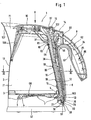
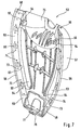
- the electrically operated kettle 1 consists of one Metal, preferably made of stainless steel, manufactured container 2, the substantially is tubular. At the filling or pouring opening 71 is a spout 107 formed for pouring or pouring water. Behind the spout 107 is located a sieve 108.
- thermostat switch 7 (only partially indicated) is electrically conductively connected.
- the electric thermostat switch 7 is via a lever (not shown) and a rocker 6 mechanically with a bent over a joint 13 Connecting rod 8 connected.
- the push rod 8 extends laterally on the container in Fig. 1 above, where it is mechanically connected to a switch button 14.
- a handle 9 On the lateral surface 12 of the container 2 is at the height of a handle 9, which is mounted later and is explained in more detail, formed from a bottom-up widening recess 17, in a corresponding to the recess 17 adapted retaining plate 18 preferably in Spot welding is attached, as illustrated in particular Fig. 5.
- Figures 1 and 5 are on the inner wall of the container 2 horizontally extending ribs 95th out, engage in the outside of the retaining plate 18 correspondingly extending ribs 96.
- the rib 97 on the retaining plate 18 is substantially U-shaped.
- the ribs 95, 96,97 serve that during the spot welding process the holding plate 18 centered about its ribs 96, 97 in the ribs 95 can be, which simplifies the mounting of the holding plate 18 on the container 2.
- Both that Holding plate 18 as the container 2 consist of one in several operations from a Blank drawn molding.
- Fig. 5 are in the recess 17 in the lower and upper region on both sides of a Longitudinal axis 22 holes 19, 20 are mounted, which connect the container interior 21 to the outside.
- the recess 17 and the retaining plate 18 are symmetrical to the longitudinal axis 22, the vertical and slightly to the container 2 upwards in the direction of the spout or Fill opening 71 is inclined, formed.
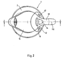
- the central axis 110 (FIG. 2) of the handle 9 also runs symmetrically to this longitudinal axis 22.
- Fig. 5 are still between the bores 19 and 20 arranged symmetrically to the longitudinal axis 22 at a distance one above the other Threaded eyes 23, 24, 25 bulged outward bulging formed.
- an opening 29 is formed, as shown in FIG. 5.
- FIG. 5 in the recess 17 is still symmetrical to the longitudinal axis 22 trained incision 30 disposed from the lateral edges 100 itself formed from sheet metal angle plates 32 raise, at its superposed tabs 99 mutually aligned and arranged vertically upwardly extending bores 31 are, as can be seen in particular from Figures 4 and 5.
- the holding plate 18 further points to the figures 4 and 5 on both sides of the longitudinal axis 22 from below above an edge 33 which is substantially parallel and spaced from the outer edge 101 of the recess 17 extends from bottom to top.
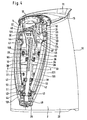
- Fig. 4 is about screws 26, 27, in the threaded eyes 23, 24 am Holding plate 18 engage, a support plate 10 on the support plate 18 and thus on the container 2 attached.
- the support plate 10 is again for clarity in Fig. 6 as a single part shown. It can be seen that for fixing the support plate 10 in this has lower and upper area bores 34, 35, wherein the lower holes 34 in the Cross-section round and the upper holes 35 in cross-section stretched upward oval are formed. This is so, because of the temperature at resulting different length change of the container made of stainless steel 2 and the carrier plate 10 made of plastic, these only upwards can extend.
- the lower screws 27 are screwed relatively firmly, while the upper screws 26 are only screwed so tightly that a relative displacement the support plate 10 is possible upwards, but still the support plate 10 always still firmly attached to the retaining plate 18 remains.
- the thermal expansion of plastic is in fact about 6 to 7 times larger than stainless steel, so that to stress on the components to avoid having to stretch without damage.
- the carrier plate 10 faces outward a bottom upwardly extending guide groove 11 which is adapted to receive a closed, serves in cross-section substantially quadrangular steam channel 36, at its upper end 102 via the formed on the support plate 10 opening 37 in the below the lid 15 formed container space 21 protrudes and its free open lower end for the purpose of temperature control to the vicinity of a bimetal (not shown) comes close, which is part of the thermal switch 7 (Fig. 1).
- the steam channel 36 is after Fig. 4 attached via side tabs 38 in the lower and upper region with the support plate 10.
- the support plate 10 has longitudinal grooves 70 and slots 39 for pivotable receiving the lid 15 and the release button 16.
- the carrier plate 10 is also formed symmetrically to the longitudinal axis 22 of the guide groove 11, that is, the holes 34, 35, the slots 39, the bearing arms 40 and the openings 41 are arranged symmetrically to the carrier plate 10.
- a leaf spring 45 is attached to the support plate 10, a Locking lever 46 resiliently presses against the switch button 14.
- the locking lever 46 is over axes 47 stored in bearing blocks 48 of the support plate 10.
- the leaf spring 45 as the locking lever 46 are arranged symmetrically to the longitudinal axis 22 of the support plate 10.
- the material of the sealing rings 44 must be so voluminous and elastic, that no leakage occurs during thermal expansion.
- hinge pins 52 used in the main part 53 of the handle 9 formed on projections 54 holes 55 engage see also Fig. 7.
- the main part 53 of the handle 9 is shown in perspective in Fig. 7 from the inside and has a formed from bottom to top, trained as strips mounting flange 56 on both sides, between the upper end, the lower half as a half-shell of the actual handle arm lower part 57 extends away, the one-piece with the mounting flange 56 is formed as a plastic part.
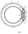
- On the two insides of the facing edges 58 are attached from bottom to top extending metal strips 59, to which bent out at substantially rectangular recesses 60 resilient hook 61 are, as this particular Fig. 3 shows.
- the metal strips 59 have over the length superimposed holes 73 which integrally formed on the main part 53 Pegs 74 are penetrated.
- the pins 74 are deformed by thermal plastic deformation such that - similar to a rivet - press the metal strip 59 against the main part 53.
- the assembly of the support plate 10, the controls 14, 16, the leaf spring 45, the Locking lever 46, the lid 15, the water level indicator 42, the push rod 8, the Rocker 6 and the main part 53 with its back part 62 is the following:
- the steam channel 36 is mounted on the support plate 10 in the guide groove 11, by his tabs 38 with the support plate 10 by means of latching hooks 63 which are connected to the Tabs 38 formed holes 64 engage behind, as indicated in FIG. 4.
- the Support plate 10 via a at the upper end downwardly open groove 81 from above the edge 82 (Fig. 5) of the incision 30 mounted.
- the support plate 10th As shown in FIG. 4 attached to the holding plate 18 and the screws 27 initially in the lower Area screwed to the container 2.
- the upper screws 26th inserted into the slots 35 and bolted to the threaded eyes 23.
- the screws 27, 26 may be, for example, self-tapping screws when screwing in the thread eyes 25, 23 there in the holes 67, 68 cut thread. But it is also conceivable, in the holes 67, 68 previously threaded by means of a tap cut and then preferably to use screws 27, 26 with metric thread. This would have the advantage that higher torques applied during screwing can be and thus a particularly strong connection exists. But it could be too previously 18 threaded sleeves are welded to the back of the retaining plate, so that longer threads are created.
- the support plate 10 is not only by the screws 26, 27 held on the container 2, but also in the upper area by the Groove 81.
- the leaf spring 45 is still attached to FIG. 4, by their to the free Leg ends trained bores 66 protruding on the support plate 10 Pins 65 are pushed and then their free ends 105 such means Heat are plastically deformed that they - similar to a rivet - the leaf spring 45 firmly hold the carrier plate 10. The other end 106 is thus elastically deformed outwards, that it presses resiliently against the blocking element 46.
- the main part 53 is formed with its projections 54 in the angle plates 32, quadrangular recordings 72 used (not shown) and is thus first in held and centered at the top. Subsequently, the main part 53 with its protruding Hook 61 so firmly pressed against the edges 33 of the holding plate 18 that the Snap hook 61 deform plastically outward, jump over the edge 33 and the Surround edge 33 of the jacket surface 12 of the container 2 facing side (Fig. 1).
- Fig. 1 is at the lower portion of the main part 53 at this an extension 76 with a Bore 77 is formed, which penetrates a screw 78 (Fig. 1) and the one in the lower Edge of the opening 29 screwed to a sheet metal tab 79 formed hole 80 is and so also the support plate 10 pulls down to the container 2 and holds stationary there.
- the release button 16, the switch button 14 and the lid 15 is not up the recess 75 can be removed, and thus at the same time the main part 53 of is closed at the top, is still the main part 53 from above closing Back portion 84 with the main part 53 over along the back portion 84 extending Locking lugs 85, which pass through correspondingly adapted holes 86, clipped.
- the unlock button 16 and the switch button 14 protrude over on the back 84th formed openings 87, 88 outwardly and are so by hand to operate accessible (Fig. 1).
- the container 2 from below an opening 89, preferably at the edge thereof diametrically opposite two part-circular recesses 90 are formed are. These recesses 90 serve to receive not shown in the drawing Display elements in the form of luminaires, which then light up when the kettle 1 is turned on.
- the display elements are part of a used in the opening 89
- Bottom part 91 (Fig. 1), via screws (not shown) with the housing of the thermostat switch 7 is connected.
- a power coupling (not shown) arranged on the touchdown on a corresponding power coupling having base 92 and when the device is powered, the heater 4 with power becomes.
Landscapes
- Engineering & Computer Science (AREA)
- Food Science & Technology (AREA)
- Cookers (AREA)
- Details Of Rigid Or Semi-Rigid Containers (AREA)
- Iron Core Of Rotating Electric Machines (AREA)
Abstract
Description
Die Erfindungen betriffen einen elektrischen Wasserkessel zum Aufheizen von Wasser gemäß
den Oberbegriffen der Patentansprüche 1 und 8.The inventions relate to an electric kettle for heating water according to
the preambles of
Ein derartiger elektrisch betriebener Wasserkessel ist bereits in der WO 00/47093 A1 beschrieben. Bei diesem Wasserkessel besteht der Behälter aus Kunststoff. Der Boden des Kunststoffbehälters ist mit einer Heizplatte versehen, an deren Unterseite die Thermostateinrichtung befestigt ist. An der Mantelfläche des Kunststoffbehälters sind Befestigungseinrichtungen sowie Lagerstellen ausgebildet, an denen sowohl der aus Kunststoff hergestellte Deckel sowie die Entriegelungstaste und die Ein- bzw. Ausschalttaste schwenkbar gelagert sind. Auch der von der Öffnung des Wasserkessels bis zum Thermoschalter nach unten führende Dampfkanal ist Bestandteil der Mantelfläche des Kunststoffbehälters, d.h. auch der Dampfkanal wird beim Spritzvorgang des Behälters mit ausgeformt.Such an electrically operated kettle is already described in WO 00/47093 A1. In this kettle, the container is made of plastic. The bottom of the Plastic container is provided with a heating plate, at the bottom of the thermostatic device is attached. On the lateral surface of the plastic container fastening means and bearings are formed, where both the plastic Lid and the unlock button and the on or off button pivotally mounted are. Also from the opening of the kettle to the thermoswitch down leading steam channel is part of the lateral surface of the plastic container, i. also the Steam channel is formed during the injection process of the container with.
Weiterhin weist der Behälter im oberen Bereich zwei Lagerzapfen auf, an denen das Hauptteil des Handgriffs mit seinen Lageraugen eingehängt und über Stehbolzen befestigt ist. Im unteren Bereich wird das Hauptteil mit der Behälterwand verschraubt. Zur Verschraubung ist die Behälterwand über den Boden nach unten hinaus so weit verlängert, daß dort Schrauben in die Behälterwand eindringen können, ohne daß Wasser austritt.Furthermore, the container in the upper region on two journals, where the Main part of the handle hung with its bearing eyes and attached via studs is. In the lower area, the main part is screwed to the container wall. For screwing the container wall is extended beyond the floor down so far that there Screws can penetrate into the container wall without water leaking.
Damit sowohl die Entriegelungstaste wie die Schalttaste den Griff nach oben durchdringen, ist der Handgriff selbst zweigeteilt und wird über ein Rückenteil von oben her verschlossen. Erst dann bildet er einen komplett ausgeformten Handgriff. Der in der WO beschriebene Wasserkessel wird bereits seit vielen Jahren von der Anmelderin selbst unter der Bezeichnung "Braun AquaExpress" vertrieben. Die Kurzbezeichnung des Gerätetyps lautet dabei WK 210 oder WK 300.So that both the release button and the switch button penetrate the handle upwards, the handle itself is divided into two parts and is closed by a back part from above. Only then does he form a completely shaped handle. The one described in WO Kettle has been used for many years by the applicant itself under the name "Braun AquaExpress" distributed. The short name of the device type is here WK 210 or WK 300.
Aufgabe der Erfindung ist es, einen Wasserkessel gemäß dem Oberbegriff derart zu verbessern, daß dieser bruchsicherer und beständiger gegen heißes Wasser und hochwertiger ausgestattet ist. Dabei soll er sich auch noch einfach montieren lassen. Weiterhin sollen die bei der Erwärmung des Wasserkessels auftretenden Wärmespannungen ohne Folgeschäden des Wasserkessels aufgefangen werden können. Schließlich soll ein Wasserkessel entstehen, dessen Herstellung trotz hochwertiger Ausstattung kostengünstig ist. The object of the invention is to improve a kettle according to the preamble in such a way that this shatterproof and more resistant to hot water and high quality Is provided. He should also be easy to assemble. Furthermore, the Thermal stresses occurring during heating of the boiler without consequential damage of the kettle can be collected. Finally, a kettle arise whose production is inexpensive despite high quality equipment.
Diese Aufgabe wird nach einer ersten Erfindung durch die kennzeichnenden Merkmale des Patentanspruchs 1 gelöst.This object is achieved according to a first invention by the characterizing features of Patent claim 1 solved.
Nach der ersten Erfindung wird eine aus Kunststoff hergestellte Trägerplatte geschaffen, die am Metallbehälter befestigt wird und die als Lager- und Aufnahmeteil sowohl für den Deckel wie für die Schalttaste oder sonstige Bedienelemente dient. Da die Integration von Schalt-Anzeigeelementen, und auch die Aufnahme des Deckels zu einem aufwendigen Aufbau eines Metallbehälters führen würde, ist gemäß der Erfindung diese Trägerplatte vorgesehen. Eine derartige Trägerplatte läßt sich nämlich in einem oder mehreren Spritzvorgängen leicht ausformen und sie kann daher aus einem besonders aufwendigen, verschachtelten Bauteil. bestehen, ohne daß die Kosten zur Erstellung des Bauteils sich erheblich erhöhen. Die erfindungsgemäße Trägerplatte hat weiterhin auch den Vorteil, daß vor Montage die Schalttaste, die Entriegelungstaste sowie alle hiermit verbundenen Bauelemente und auch weitere Bedienelemente, falls erforderlich, in der Trägerplatte vormontiert werden können und erst dann an der Behälterwand montiert wird. Der Deckel kann dann in seiner Lagerung an der Trägerplatte eingebracht werden.According to the first invention, a carrier plate made of plastic is provided which is attached to the metal container and as storage and receiving part for both the lid as used for the button or other controls. Since the integration of switching display elements, and the inclusion of the lid to a complex structure of a Metal container would lead, according to the invention, this support plate is provided. Namely, such a carrier plate can be easily in one or more injection operations ausformen and they can therefore from a particularly complex, nested component. exist without significantly increasing the cost of constructing the component. The inventive Carrier plate also has the advantage that before mounting the button, the unlock button as well as all related components and more Operating elements, if necessary, can be pre-assembled in the carrier plate and only then mounted on the container wall. The lid can then be stored in its storage at the Carrier plate are introduced.
Da ein derartiger Wasserkessel zum Zwecke der Temperaturüberwachung in der Regel mit einem Dampfkanal ausgestattet ist, über den Dampf zu dem unterhalb der Heizeinrichtung ausgebildeten Thermostaten geführt wird, wenn das Wasser zu kochen beginnt, ist es vorteilhaft, wenn auch dieser Dampfkanal in der Trägerplatte integriert ist, bzw. in ihr montiert ist. Auch dieser Dampfkanal ist als eigenständiges Bauteil aus Kunststoff ausgeformt und wird anschließend vor Montage der Trägerplatte am Stahlbehälter an dieser montiert.Since such a kettle for the purpose of temperature monitoring usually with a steam channel is provided, via the steam to the below the heater trained thermostat is run, when the water begins to boil, it is beneficial although this steam channel is integrated in the carrier plate, or mounted in it is. Also, this steam channel is formed as an independent component made of plastic and is then mounted on the steel container before assembly of the support plate.
Weist der Wasserkessel als weiteres Bedienelement zusätzlich noch eine Entriegelungstaste
auf, die dazu dient, den Deckel nur dann zu öffnen, wenn die Heizeinrichtung abgeschaltet
ist, so kann diese gemäß einer Weiterbildung der Erfindung nach Anspruch 3
ebenfalls in der Trägerplatte gelagert und vormontiert sein. Gleiches gilt für die Sperr- und
Entriegelungselemente, wie sie in der zuvor erwähnten WO beschrieben sind. Die dort beschriebene
Sicherheitsvorrichtung, bestehend aus Sperrelement, Betätigungselement, Taste,
Schubstange, Deckel, Druckfeder, sind auch bei dem Wasserkessel nach der Erfindung
Bestandteile, nur sind sie hier nicht am Behälter des Behälters, sondern an der Trägerplatte
befestigt, an der hierzu gesonderte Aufnahmen vorgesehen sind. Zur Ausstattung und
Funktionsweise kann also direkt auf den Offenbarungsgehalt dieser WO zurückgegriffen
werden, der somit auch Bestandteil dieser Anmeldung ist. If the kettle also has a release button as a further control element
on, which serves to open the lid only when the heater is turned off
is, it may according to a development of the invention according to
Durch die Merkmale des Patentanspruchs 5 wird erfindungsgemäß die Befestigungseinrichtung
von einem an der Mantelfläche des Metallbehälters angeschweißten Halteblech
gebildet, das Befestigungseinrichtungen aufweist, an die die Trägerplatte befestigt wird.
Selbstverständlich wäre es auch denkbar, direkt an die Mantelfläche des Wasserkessels
Gewindeaugen, Lagerzapfen oder sonstige Befestigungselemente aus Metall anzuschweißen,
dies würde aber die Herstellungskosten des Wasserkessels erhöhen, weil dann viele
einzelne Schweißvorgänge erforderlich wären. Viel einfacher ist es daher nach der Erfindung,
ein Halteblech im Punktschweißvorgang an die Oberfläche des Behälters anzuschweißen,
das dann die zahlreichen Befestigungselemente aufweist. Dieses Halteblech
kann nämlich zuvor in einem Stanzvorgang ausgestanzt, entsprechend gebogen und gegebenenfalls
mit Gewindestiften oder Gewindeaugen versehen sein. Ein derartiger Vorgang ist
schnell und verhältnismäßig kostengünstig durchführbar. Erst dann wird dieses Halteblech in
einem einzigen Arbeitsgang an die Mantelfläche des aus Metall hergestellten Behälters angeschweißt,
vorzugsweise im Punktschweißverfahren.Due to the features of
Ein weiterer Vorteil besteht darin, daß dieses Halteblech einen geringen Abstand zur Oberfläche des Behälters aufweist und somit als Wärmesperre dient, damit nicht allzu viel Wärme in die aus Kunststoff hergestellten Teile, wie die Trägerplatte und den Handgriff sowie den Deckel, eindringen kann. Hierzu sind an dem Halteblech Abstandsrippen angeformt, die - außer an den Schweißpunkten - das Blech auf Abstand zur Außenfläche des Behälters halten. Ein weiterer Vorteil besteht darin, daß, wenn Gewindeaugen als einer der Befestigungselemente gewählt werden, diese nicht die Oberfläche des Behälters, was sich insbesondere auch an der Innenwand des Behälters zeigen würde, unterbricht, wo dann Schmutz eindringt, der dann verhältnismäßig schwer entfernt werden könnten.Another advantage is that this holding plate a small distance from the surface has the container and thus serves as a thermal barrier, so not too much heat in the parts made of plastic, such as the support plate and the handle and the Cover, can penetrate. For this purpose, spacer ribs are integrally formed on the holding plate, the - except at the welding points - keep the sheet at a distance from the outer surface of the container. Another advantage is that when threaded eyes as one of the fasteners These are not the surface of the container, which in particular would also show on the inner wall of the container interrupts, where then enters dirt, which would then be relatively difficult to remove.
Durch die Merkmale des Patentanspruchs 6 wird der unterschiedlichen Wärmeausdehnung
unterschiedlicher Werkstoffe Rechnung getragen, indem der untere Teil der Trägerplatte wie
ein festes Lager eingespannt ist, während hingegen der obere Teil sich nach oben hin bei
Wärmeeinwirkung unabhängig gegenüber der Wärmeausdehnung des Metallbehälters ausdehnen
kann. Hierzu dienen die an den oberen Bohrungen in der Trägerplatte ausgebildeten
Langlöcher, die Schrauben durchdringen und die nur so leicht angezogen werden, daß eine
Bewegung der Trägerplatte nach oben möglich ist, daß aber diese dennoch über die Verschraubung
ortsfest am Behälter gehalten wird. Auf diese Weise werden unzulässig hohe
Spannungen in der Trägerplatte vermieden, die gegebenenfalls dann zum Bruch dieser führen
könnte. Due to the features of
Besonders vorteilhaft ist es bei dieser Befestigung, wenn die Trägerplatte am oberen Rand der Öffnung zusätzlich noch lose eingehängt ist (Anspruch 7). Auch dann, wenn sich nämlich die Trägerplatte nach oben bei Temperatureinwirkung verlängert, kann diese nicht aus der Einhängung herausgleiten, weil die Überlappung der Trägerplatte mit der Innenwand des Behälters größer ist als die maximale Verformung. Durch die Einhängung der Trägerplatte kann sich diese nach oben hin unter Vermeidung von Spannungen ausdehnen. Da alle Bedienelemente sowie die Sperreinrichtung in der Trägerplatte befestigt sind, wird auch auf dieser keine Spannung infolge Wärmeausdehnung ausgeübt, da sie bei Ausdehnung der Trägerplatte mehr oder weniger angehoben werden, was sich allerdings im Millimeterbereich erstreckt.It is particularly advantageous in this attachment, when the carrier plate at the top the opening is additionally hung loosely (claim 7). Even if that is true the support plate extended upwards under the influence of temperature, this can not slip out of the suspension, because the overlap of the support plate with the inner wall of the Container is greater than the maximum deformation. By the suspension of the carrier plate This can expand upwards while avoiding tensions. Because all controls as well as the locking device are fixed in the carrier plate, is also on this exerted no tension due to thermal expansion, since they are at extension of the Carrier plate are raised more or less, which, however, in the millimeter range extends.
Nach der zweiten Erfindung gemäß den Merkmalen des Patentanspruchs 8 weist der Handgriff
einen entlang der Mantelfläche des Behälters verlaufenden Befestigungsflansch auf, an
dessen Innenseite an Rändern Metalleisten befestigt sind, die in Eingriff mit dem Halteblech
gelangen, wenn der Handgriff befestigt wird. Selbstverständlich könnte man auch anstelle
der Metalleisten an dem Befestigungsflansch des Handgriffs Haltenasen ausbilden, die einteilig
mit dem Handgriff aus Kunststoff ausgeformt sind, doch diese könnten bei Einwirkung
unter Temperatur über einen langen Zeitraum schmelzen oder brechen, was zum Lösen des
Handgriffs vom Metallbehälter führen könnte. Dies könnte dann verheerende Folgen haben,
wenn der Wasserkessel mit kochendem Wasser auf den Boden fällt und kochendes Wasser
herumspritzt. Um diesen Fall absolut zu vermeiden, sind daher über die nahezu gesamte
Länge des Befestigungsflanschs an den seitlichen Rändern je eine Metalleiste mit federnden
Haken angebracht, die bei Montage sich elastisch aufweiten und anschließend den Rand
des Halteblechs unverlierbar hintergreifen. Die Metalleisten sind in das Spritzwerkzeug, das
den Handgriff ausformt, eingelegt und werden so teilweise formschlüssig umspritzt. Es ist
aber auch durchaus möglich, nach dem Spritzvorgang des Handgriffs die Haltebleche an
den Rändern des Handgriffs anzulegen und dann mittels am Handgriff ausgebildeten Nasen
diese so zu erwärmen, daß sie das Halteblech teilweise formschlüssig umgreifen, ähnlich
einem Nietvorgang.According to the second invention according to the features of
Unabhängig von der Befestigung der Trägerplatte an dem Halteblech wird der Handgriff ebenfalls an dem Halteblech befestigt, wobei hier andere Befestigungspunkte als bei der Befestigung der Trägerplatte benutzt werden. Dies hat den entscheidenden Vorteil, daß bei einwirkender Wärme sowohl auf das Halteblech wie auf den Handgriff sich diese Teile nicht gegenseitig infolge der durch die auftretende Wärmespannung einsetzende Ausdehnung nachteilig beeinflussen können. Dies ist insbesondere dann wichtig, wenn ein langes mechanisches Verbindungsglied, nämlich eine Schubstange, zwischen der Schalttaste und dem Thermoschalter vorhanden ist, das bereits bei geringsten Verschiebungen ein Schaltvorgang auslöst, weil die an dem Thermostatschalter vorgesehenen Schaltwege in sehr engen Toleranzen gehalten sind.Regardless of the attachment of the carrier plate to the retaining plate is the handle also attached to the retaining plate, here other attachment points than in the Attachment of the carrier plate can be used. This has the decisive advantage that at acting heat both on the retaining plate as on the handle, these parts are not mutually as a result of the onset of thermal stress occurring expansion adversely affect. This is especially important if a long mechanical Link, namely a push rod, between the switch button and the Thermal switch is present, the switching even with the slightest shifts triggers because provided on the thermostatic switch gears in very tight tolerances are held.
Durch die zweite Erfindung ist es möglich, daß sich der Handgriff bei seiner Erwärmung durch den Stahlbehälter unabhängig gegenüber der Trägerplatte über den Rand des Halteblechs entweder nach oben oder nach unten verschieben kann, weil die Haken in Längsrichtung auf dem Rand, der hier die Funktion einer Schiene übernimmt, hin- und hergleiten können. Auf diese Weise werden Spannungen aufgrund von Temperatureinwirkung am Handgriff vermieden. Dies ist insbesondere deshalb wichtig, weil Kunststoff sich gegenüber Stahl fast um das Siebenfache mehr ausdehnt und daher, wenn diese Kunststoffteile fest mit dem Behälter verschraubt wären, zwangsweise zum Bruch dieser Teile auf längere Zeit führen würden. Die Trägerplatte ist also etwa mittig am Halteblech fest eingespannt und kann sich bei Wärmeeinfluß über die Mitte sowohl nach oben wie nach unten ausdehnen. Diese Ausdehnungen werden bei der konstruktiven Auslegung der einzelnen zusammenwirkenden Bauteile derart berücksichtigt, daß anschließend nach Montage im Betrieb eines erfindungsgemäßen Wasserkessels diese Wärmeausdehnungen so ineinander greifen, daß weder Fehlschaltungen noch Ausfälle durch Wärmeeinwirkung entstehen können.By the second invention, it is possible that the handle during its heating through the steel container independently of the support plate over the edge of the retaining plate can move either up or down because the hooks are longitudinal on the edge, which here assumes the function of a rail, slide back and forth can. In this way, stresses due to temperature on the Handle avoided. This is especially important because plastic faces Steel expands almost seven times more and therefore, if these plastic parts stuck with screwed to the container, forcibly lead to breakage of these parts for a long time would. The support plate is thus firmly clamped in the middle of the holding plate and can to expand both vertically upwards and downwards as heat is applied across the middle. These Extensions are used in the constructive design of each cooperating Considered components such that subsequently after assembly during operation of an inventive Kettle these thermal expansions mesh so that neither Failures still failures can occur due to heat.
Selbstverständlich ist es auch denkbar, die Haken bei Montage des Handgriffs nicht radial nach außen aufweiten zu lassen, sondern die Haken und den Rand so auszubilden, daß der Handgriff - ähnlich einer Schiebekulisse - auf den Rand von der einen Seite her augeschoben wird und dabei die beiden gegenüberstehenden Hakenlesten den Rand spielfrei um- bzw. hintergreifen.Of course, it is also conceivable that the hooks when mounting the handle is not radial to expand outward, but the hook and the edge in such a way that the Handle - similar to a sliding gate - on the edge of the one side pushed out while the two opposing hook loads cross the edge without clearance. or behind.
Durch die Merkmale des Patentanspruchs 9 wird nun festgelegt, daß der der Öffnung zugewandte
Bereich des Handgriffs am Behälter ortsfest befestigt wird, also das Festlager bildet,
während sich bei Längenausdehnung das andere Ende zum Boden hin ausdehnen kann.
Auf diese Weise kann sich der Handgriff nicht verbiegen und es bleibt dessen Rand immer
bündig an der Mantelfläche des Behälters zur Anlage, so daß kein Schmutz von außen in die
Vertiefung und die Trägerplatte eindringen kann. Hierzu ist vorteilhafterweise weiterhin der
Rand des Befestigungsflansches des Handgriffes so elastisch ausgebildet, daß er stets dicht
an der Mantelfläche anliegt. By the features of
Nach den Merkmalen des Patentanspruchs 10 ist der Abstand zwischen den gegenüberliegenden
Rändern am Halteblech so genau vermaßt und toleriert, was selbstverständlich auch
für die Abstände der gegenüberliegenden Haken an den Blechleisten am Handgriff stimmen
muß. Dies ist deshalb erforderlich, daß ohne allzu große Anpreßkräfte der Handgriff am
Halteblech durch Aufspreizen der Haken und anschließend Hintergreifen der Ränder montiert
werden kann. Selbstverständlich könnte man die enge Toleranz über die gesamte Länge
des Randes am Halteblech einhalten, dies wäre aber mit erhöhten Kosten verbunden.
Daher sind nur diejenigen Bereiche genau toleriert, an denen die Haken angreifen und diese
Bereiche mittels plastischer Verformung übergreifen und anschließen hintergreifen müssen.
Sind dabei gemäß den Merkmalen des Patentanspruchs 11 diese Bereiche von Vertiefungen
gebildet, die in ihrer Längsrichtung etwas größer sind als die Länge der Rasthaken, so müssen
nur diese Bereiche in engen Maßen kalibriert werden, was die Herstellkosten reduziert.
Die Bereiche müssen länger sein als die Länge der Haken, damit sich bei der Ausdehnung
infolge von Temperatureinwirkung die Haken in diesen Bereichen hin- und herbewegen können.According to the features of
Um den Handgriff über seine Lageraugen an den am Halteblech ausgebildeten Lagerzapfen
mittels Stehbolzen zu befestigen, werden die Stehbolzen von oben her über den Handgriff in
die Bohrungen der Lageraugen und Lagerzapfen eingeführt, wenn die Bohrungen zueinander
fluchten. Will man die Befestigungsstellen des Handgriffs nicht von außen erkennen, so
muß man den Handgriff gemäß den Merkmalen des Patentanspruchs 12 im oberen Bereich
zweiteilen, was durch einen nach oben offenen Handgriff erfolgt, der anschließend nach
Verschließen des Hauptteils durch das Rückenteil von oben her abgedeckt wird. Gleichzeitig
wird auch der ganze obere Teil des Trageteils, in dem die Rückstelltaste, die Schalttaste und
der Deckel gelagert ist, von oben her abgedeckt und ist somit verliersicher an der Trägerplatte
befestigt.To the handle on its bearing eyes on the bearing pin formed on the bearing journal
by means of stud bolts, the studs are from above the handle in
introduced the holes of the bearing eyes and journals when the holes to each other
aligned. If you do not want to see the attachment points of the handle from the outside, so
you have the handle according to the features of
Ein Ausführungsbeispiel beider Erfindungen ist in der Zeichnung dargestellt und wird im folgenden näher erläutert. Es zeigen:
- Fig. 1
- einen Längsschnitt durch die Mitte eines erfindungsgemäßen elektrisch betriebenen Wasserkessels, wobei der Schnitt gemäß der Schnittführung I-I nach Fig. 2 geführt wurde,
- Fig. 2
- eine Draufsicht in Richtung X von oben auf den Wasserkessel nach Fig. 1, allerdings in verkleinertem Maßstab gegenüber Fig. 1 dargestellt,
- Fig. 3
- einen Schnitt quer durch den Wasserkessel gemäß der Schnittführung III-III nach Fig. 1,
- Fig. 4
- eine perspektivische Darstellung schräg von der Seite auf die den Handgriff aufnehmende Wasserkesselpartie, wobei allerdings zur besseren Verdeutlichung hier der Handgriff noch nicht montiert ist,
- Fig. 5
- eine perspektivische Darstellung auf die Handgriffseite des aus vorzugsweise Edelstahl tiefgezogenen Behälters als Basisteil im noch nicht montierten Zustand, an dessen äußerer Mantelfläche im Handgriffbereich ein Halteblech aufgeschweißt ist,
- Fig. 6
- eine perspektivische Darstellung einer aus Kunststoff gespritzten Trägerplatte und
- Fig. 7
- eine perspektivische Darstellung eines Handgriffs von der Befestigungsseite her.
- Fig. 1
- 3 a longitudinal section through the center of an electrically operated water boiler according to the invention, the section being guided according to the sectional guide II according to FIG. 2,
- Fig. 2
- a top view in the direction X of the top of the kettle according to FIG. 1, but shown on a reduced scale compared to FIG. 1,
- Fig. 3
- a section across the kettle according to the section III-III of Fig. 1,
- Fig. 4
- a perspective view obliquely from the side on the handle receiving water kettle lot, although here for better clarity here the handle is not mounted,
- Fig. 5
- a perspective view of the handle side of the preferably stainless steel deep-drawn container as a base part in the not yet assembled state, on the outer lateral surface in the handle area a retaining plate is welded,
- Fig. 6
- a perspective view of a molded plastic carrier plate and
- Fig. 7
- a perspective view of a handle from the mounting side.
In den Figuren 1 bis 3 besteht der elektrisch betriebene Wasserkessel 1 aus einem aus
Metall, vorzugsweise aus nichtrostendem Edelstahl, hergestellten Behälter 2, der im wesentlichen
rohrförmig ausgebildet ist. An der Einfüll- bzw. Ausgießöffnung 71 ist eine Schnaupe
107 zum Ein- bzw. Ausgießen von Wasser angeformt. Hinter der Schnaupe 107 befindet
sich ein Sieb 108.In FIGS. 1 to 3, the electrically operated kettle 1 consists of one
Metal, preferably made of stainless steel, manufactured
Im unteren Bereich des Wasserkessels 1 ist nach Fig. 1 ein aus Edelstahl eingesetzter Boden
3 dichtend befestigt. Unterhalb des Bodens 3 ist an diesem ein ringförmiges elektrisch
betriebenes Heizelement 4 gut wärmeleitend befestigt, bzw. mit diesem über eine aus Aluminium
hergestellte Diffusionsplatte 98 verlötet oder verschweißt. Das Heizelement 4 weist
nach Figur 1 an seinen Enden, wobei nur ein Ende gezeigt ist, je eine Kontaktfahne 5 auf,
die über in der Zeichnung nicht dargestellte Leitungen mit einem innerhalb der rohrförmigen
Heizung 4 am Boden 3 ausgebildeten Thermostatschalter 7 (nur teilweise angedeutet)
stromleitend verbunden ist. Der elektrische Thermostatschalter 7 ist über einen Hebel (nicht
dargestellt) und eine Wippe 6 mechanisch mit einer über ein Gelenk 13 abgewinkelten
Schubstange 8 verbunden. Die Schubstange 8 verläuft seitlich am Behälter in Fig. 1 nach
oben und ist dort mechanisch mit einer Schalttaste 14 verbunden.In the lower part of the kettle 1 of Fig. 1 is a
An dieser Stelle wird nochmals erwähnt, daß die gesamte Elektrik sowie die mechanische
Betätigung der elektrischen Schalteinrichtung und die Hebelanordnung zum Versperren des
Deckels 15, die von einem Sperrhebel 46 gesteuert wird, der seinerseits den Deckel 15 und
die Entriegelungstaste 16 steuert, bereits in der WO 00/47093 und dem im Handel seit langem
erhältlichen Wasserkessel WK 200/300, wie eingangs beschrieben, offenbart ist und
daher, falls hieraus Offenbarungselemente für den Gegenstand dieser Anmeldung erforderlich
sind, hieraus entnommen und Gegenstand dieser Anmeldung werden können. Zur Vermeidung
von Wiederholungen wird daher auf diese Gemeinsamkeiten nicht mehr eingegangen.At this point it is mentioned again that the entire electrical system as well as the mechanical
Actuation of the electrical switching device and the lever arrangement for locking the
An der Mantelfläche 12 des Behälters 2 ist auf der Höhe eines Handgriffs 9, der später montiert
und näher erklärt wird, eine sich von unten nach oben erweiternde Vertiefung 17 angeformt,
in der ein entsprechend der Vertiefung 17 angepaßtes Halteblech 18 vorzugsweise im
Punktschweißverfahren befestigt ist, wie dies insbesondere Fig. 5 verdeutlicht. Nach den
Figuren 1 und 5 stehen an der Innenwand des Behälters 2 horizontal verlaufende Rippen 95
hervor, in die von außen an dem Halteblech 18 entsprechend verlaufende Rippen 96 eingreifen.
Im oberen Bereich verläuft die Rippe 95 am Behälter 2 und die Rippe 97 am Halteblech
18 im wesentlichen U-förmig. Die Rippen 95, 96,97 dienen dazu, daß beim Punktschweißvorgang
das Halteblech 18 über seine Rippen 96, 97 in den Rippen 95 zentriert
werden kann, was die Montage des Halteblechs 18 am Behälter 2 vereinfacht. Sowohl das
Halteblech 18 wie der Behälter 2 bestehen aus einem in mehreren Arbeitsgängen aus einem
Rohling gezogenen Formteil.On the
Nach Fig. 5 sind in der Vertiefung 17 im unteren und oberen Bereich zu beiden Seiten einer
Längsachse 22 Bohrungen 19, 20 angebracht, die das Behälterinnere 21 nach außen verbinden.
Nach Fig. 5 sind die Vertiefung 17 sowie das Halteblech 18 symmetrisch zur Längsachse
22, die senkrecht und leicht zum Behälter 2 nach oben in Richtung der Ausguß- bzw.
Einfüllöffnung 71 geneigt verläuft, ausgebildet. Die Mittelachse 110 (Fig. 2) des Handgriffs 9
verläuft ebenfalls symmetrisch zu dieser Längsachse 22. In Fig. 5 sind weiterhin zwischen
den Bohrungen 19 und 20 symmetrisch zur Längsachse 22 im Abstand übereinander angeordnete
Gewindeaugen 23, 24, 25 nach außen hin ausgewölbt ausgeformt. Am Behälter 2
schließt sich unterhalb des Bodens 3 (Fig. 1) ein Rand 28 an, in dem in Verlängerung der
Vertiefung 17 eine Öffnung 29 ausgebildet ist, wie dies Fig. 5 zeigt.According to Fig. 5 are in the
Am oberen Ende ist weiterhin nach Fig. 5 in der Vertiefung 17 ein zur Längsachse 22 symmetrisch
ausgebildeter Einschnitt 30 angeordnet, von dessen seitlichen Rändern 100 sich
aus Blech geformte Winkelbleche 32 erheben, an dessen übereinander angeordneten Laschen
99 zueinander fluchtende und senkrecht nach oben verlaufende Bohrungen 31 angeordnet
sind, wie dies insbesondere aus Figuren 4 und 5 ersichtlich ist. Das Halteblech 18
weist weiterhin nach den Figuren 4 und 5 beiderseits der Längsachse 22 von unten nach
oben einen Rand 33 auf, der im wesentlichen parallel und mit Abstand zum äußeren Rand
101 der Vertiefung 17 von unten nach oben verläuft.At the upper end of FIG. 5 in the
Wie aus Fig. 4 hervorgeht, ist über Schrauben 26, 27, die in die Gewindeaugen 23, 24 am
Halteblech 18 eingreifen, eine Trägerplatte 10 an dem Halteblech 18 und somit am Behälter
2 befestigt. Die Trägerplatte 10 ist zur besseren Verdeutlichung nochmals in Fig. 6 als Einzelteil
dargestellt. Daraus ist zu erkennen, daß zur Befestigung der Trägerplatte 10 diese im
unteren und oberen Bereich Bohrungen 34, 35 aufweist, wobei die unteren Bohrungen 34 im
Querschnitt rund und die oberen Bohrungen 35 im Querschnitt nach oben gestreckt oval
ausgebildet sind. Dies ist deshalb so, damit aufgrund der bei einwirkender Temperatur sich
ergebenden unterschiedlichen Längenänderung von dem aus Edelstahl hergestellten Behälter
2 und der aus Kunststoff hergestellten Trägerplatte 10 sich diese nur nach oben hin
verlängern kann. Dazu sind die unteren Schrauben 27 verhältnismäßig fest angeschraubt,
während die oberen Schrauben 26 nur so fest angeschraubt sind, daß eine relative Verschiebung
der Trägerplatte 10 nach oben möglich ist, aber dennoch die Trägerplatte 10 immer
noch fest an dem Halteblech 18 befestigt bleibt. Die Wärmeausdehnung von Kunststoff
ist nämlich etwa 6 bis 7 mal größer als von Edelstahl, so daß, um Spannungen an den Bauteilen
zu vermeiden, diese sich schadlos ausdehnen müssen.As is apparent from Fig. 4, is about screws 26, 27, in the threaded
Wie aus den Figuren 4 und 6 weiter ersichtlich ist, weist die Trägerplatte 10 nach außen hin
eine von unten nach oben verlaufende Führungsnut 11 auf, die zur Aufnahme eines geschlossenen,
im Querschnitt im wesentlichen viereckigen Dampfkanals 36 dient, der an seinem
oberen Ende 102 über die an der Trägerplatte 10 ausgebildete Öffnung 37 in den unterhalb
des Deckels 15 ausgebildeten Behälterraum 21 hineinragt und dessen freies offenes
untere Ende zum Zwecke der Temperatursteuerung an die Nähe eines Bimetalls (nicht dargestellt)
heranreicht, das Teil des Thermoschalters 7 ist (Fig. 1). Der Dampfkanal 36 ist nach
Fig. 4 über seitliche Laschen 38 im unteren und oberen Bereich mit der Trägerplatte 10 befestigt.
Im oberen Bereich weist die Trägerplatte 10 Längsnuten 70 und Schlitze 39 zur
schwenkbaren Aufnahme des Deckels 15 und der Entriegelungstaste 16 auf. Weiterhin sind
im oberen Bereich zwei Lagerarme 40 angeordnet, die zur Lagerung der Schalttaste 14 und
der Schubstange 8 dienen. Schließlich sind noch zwei Öffnungen 41 vorhanden, die als
Durchbruch der Arme 104 der Entriegelungstaste 16 dienen, über die bei Betätigung der
Entriegelungstaste 16 der Deckel 15 geöffnet wird. Auf weitere Details der Bedienelemente
14, 16 wird hier nicht näher eingegangen, da diese ebenfalls bereits in dem oben in der WO
beschriebenen Wasserkessel entsprechend ausgebildet sind, allerdings dort nicht in einer
Trägerplatte, sondern direkt an dem aus Kunststoff ausgeformten Behälter.As can also be seen from FIGS. 4 and 6, the
Die Trägerplatte 10 ist ebenfalls symmetrisch zur Längsachse 22 der Führungsnut 11 ausgebildet,
d.h., die Bohrungen 34, 35, die Schlitze 39, die Lagerarme 40 sowie die Öffnungen
41 sind symmetrisch zur Trägerplatte 10 angeordnet.The
Wie aus Fig. 4 ersichtlich ist, sind seitlich vor der Trägerplatte 10 rohrförmige und durchsichtige
Wasserstandsanzeigen 42 aus Kunststoff angeordnet, die über Winkelstücke 43 am
oberen und unteren Ende in die am Behälter 2 ausgebildeten Bohrungen 19, 20 hineinragen
und dort über Dichtringe 44 gegenüber der Wand der Bohrungen 19, 20 des Behälters 2
gedichtet sind. Weiterhin ist an der Trägerplatte 10 eine Blattfeder 45 befestigt, die einen
Sperrhebel 46 gegen die Schalttaste 14 federnd drückt. Der Sperrhebel 46 ist über Achsen
47 in Lagerböcken 48 der Trägerplatte 10 gelagert. Auch die Blattfeder 45 wie der Sperrhebel
46 sind symmetrisch zur Längsachse 22 der Trägerplatte 10 angeordnet.As can be seen from Fig. 4, are laterally in front of the
Im unteren Bereich des Behälters 2 ragt nach Fig. 4 die Wippe 6 über die am Behälter 2
ausgebildete Öffnung 29 von innen durch die Trägerplatte 10 und wird in den Zapfaufnahmen
49 an der Trägerplatte 10 von außen her gehalten und geführt. Schließlich werden
noch nach Fig. 4 die unteren Abschnitte der Wasserstandsanzeigen 42 von Blechelementen
51, die über Schrauben 50 in den Gewindeaugen 25 befestigt sind, ortsfest gehalten. Bei
Temperatureinwirkung können sich die Wasserstandsanzeigen 42 nur nach oben hin ausdehnen
und dabei die Dichtringe 44 mehr oder weniger nach oben gegen die Wand der Bohrungen
20 drücken. Dabei muß das Material der Dichtringe 44 so volumig und elastisch sein,
daß bei der Wärmeausdehnung keine Undichtigkeit entsteht.In the lower region of the
Wie aus Fig. 4 weiterhin ersichtlich ist, sind von oben her in die an den Winkelblechen 32
ausgebildeten Bohrungen 31 Gelenkstifte 52 eingesetzt, die in am Hauptteil 53 des Handgriffs
9 an Vorsprüngen 54 ausgebildete Bohrungen 55 eingreifen (siehe hierzu auch Fig. 7).
Das Hauptteil 53 des Handgriffs 9 ist in Fig. 7 von der Innenseite her perspektivisch dargestellt
und weist einen von unten nach oben angeformten, als Leisten ausgebildeten Befestigungsflansch
56 zu beiden Seiten auf, zwischen dessen oberen Ende sich die untere Hälfte
als Halbschale des eigentlichen Handgriffarmunterteils 57 weg erstreckt, das einteilig mit
dem Befestigungsflansch 56 als Kunststoffteil ausgeformt ist. An den beiden Innenseiten der
zugewandten Ränder 58 sind von unten nach oben verlaufende Blechleisten 59 befestigt, an
denen an im wesentlichen viereckigen Ausnehmungen 60 federnde Haken 61 herausgebogen
sind, wie dies insbesondere auch Fig. 3 zeigt. Die Blechleisten 59 weisen über die Länge
übereinander angeordnete Bohrungen 73 auf, die von an dem Hauptteil 53 angeformten
Zapfen 74 durchdrungen werden. Zur Befestigung der Blechleisten 59 an dem Hauptteil 53
werden die Zapfen 74 durch thermische plastische Verformung derart verformt, daß sie -
ähnlich einem Niet - die Blechleiste 59 gegen das Hauptteil 53 pressen. Schließlich wird
noch erwähnt, daß das Hauptteil 53 nach Fig. 7 Längsöffnungen 93 aufweist, über die gemäß
Fig. 2 die Wasserstandsanzeigen 42 teilweise nach außen ragen, um so den Füllstand
im Behälterinnern 21 erkennen zu können, wenn auch der Deckel 15 die obere Einfüllöffnung
71 verschließt. Der Rand 94 der Längsöffnungen 93 liegt im montierten Zustand an der
Oberfläche der Wasserstandsanzeige 42 an und hält somit diese gegen radiales Lösen.As can also be seen from FIG. 4, from above into the
Die Montage der Trägerplatte 10, der Bedienelemente 14, 16, der Blattfeder 45, des
Sperrhebels 46, des Deckels 15, der Wasserstandsanzeige 42, der Schubstange 8, der
Wippe 6 und des Hauptteils 53 mit seinem Rückenteil 62 ist folgende:The assembly of the
Zunächst wird auf der Trägerplatte 10 in der Führungsnut 11 der Dampfkanal 36 montiert,
indem er über seine Laschen 38 mit der Trägerplatte 10 mittels Rasthaken 63, die an den
Laschen 38 ausgebildete Bohrungen 64 hintergreifen, wie dies Fig. 4 andeutet. Nun wird die
Trägerplatte 10 über eine am oberen Ende nach unten hin offene Nut 81 von oben her an
dem Rand 82 (Fig. 5) des Einschnitts 30 eingehängt. Anschließend wird die Trägerplatte 10
gemäß Fig. 4 an dem Halteblech 18 angesetzt und über die Schrauben 27 zunächst im unteren
Bereich mit dem Behälter 2 verschraubt. Anschließend werden die oberen Schrauben 26
in die Langlöcher 35 eingeführt und mit den Gewindeaugen 23 verschraubt. Die Schrauben
27, 26 können beispielsweise selbstschneidende Schrauben sein, die beim Einschrauben in
die Gewindeaugen 25, 23 dort in den Bohrungen 67, 68 Gewinde einschneiden. Es ist aber
auch denkbar, in die Bohrungen 67, 68 vorher Gewinde mittels eines Gewindeschneiders
einzuschneiden und dann vorzugsweise Schrauben 27, 26 mit metrischem Gewinde zu verwenden.
Dies hätte den Vorteil, daß höhere Drehmomente beim Verschrauben aufgebracht
werden können und somit eine besonders feste Verbindung besteht. Es könnten aber auch
zuvor an der Rückseite des Halteblechs 18 Gewindehülsen angeschweißt werden, so daß
längere Gewinde geschaffen werden. Die Trägerplatte 10 wird nicht nur durch die Schrauben
26, 27 am Behälter 2 gehalten, sondern zusätzlich noch im oberen Bereich durch die
Nut 81. Dabei ergibt sich auch noch der Vorteil, daß bei Wärmeeinwirkung sich die Trägerplatte
10 nach oben verschieben kann, ohne daß der Rand 82 aus der Nut 81 gleitet. Zur
Wärmeisolation und zum reibfesten Eingriff ist noch in der Nut 81 ein U-förmiger Dichtstreifen
83 eingelegt, der den Rand 82 umschließt und der nach Montage in der Nut 81 eingepreßt
wird.First, the
Nun werden die beiden Wasserstandsanzeigen 42 mit ihren Winkelstücken 43, auf denen
bereits zuvor die Dichtringe 44 aufgesetzt wurden, von außen in die Bohrungen 19, 22 dichtend
eingepreßt. Damit die Wasserstandsanzeigen 42 sich nicht während des Gebrauchs
und aufgrund von Temperatureinwirkung wieder aus ihren Bohrungen 19, 20 lösen können,
werden sie mittels der Schrauben 50 über die an den Gewindeaugen 25 ausgebildeten Bohrungen
69 mit dem Behälter 2 verschraubt. Dabei wird das mit dem Schrauben 50 verbundenes
Blechelement 51 gegen das untere Ende der Wasserstandsanzeige 42 gedrückt und
hält somit dieses Ende fest am Behälter 2.Now the two
Im nächsten Montagegang werden nunmehr über die am oberen freien Ende der Trägerplatte
10 ausgebildeten Schlitze 70 (Fig. 6) die am Deckel 15 ausgebildeten Schwenkarme
(nicht dargestellt) eingeführt, so daß der Deckel 15 nach Lösen in die Einfüll- bzw. Ausgießöffnung
71 des Behälters 2 schwenkt und dort zum Anschlag kommt und somit die Einfüll-
bzw. Ausgießöffnung 71 verschließt. Anschließend werden die Entriegelungstaste 16, die
Schalttaste 14 und der Sperrhebel 46 in den hierzu vorgesehenen Aufnahmen montiert.
Schließlich wird noch die mit der Schubstange 8 gelenkig verbundene Wippe 6 so montiert,
daß das der Wippe 6 gegenüberliegende freie Ende in Glenkeingriff mit der Schalttaste 14
gelangt, was aber in den Zeichnungen nicht ersichtlich ist, was aber ebenfalls bereits aus
der zuvor beschriebenen WO identisch dieser Lösung ist.In the next assembly cycle are now on the upper free end of the
Am Schluß wird noch die Blattfeder 45 nach Fig. 4 befestigt, indem ihre an den freien
Schenkelenden ausgebildeten Bohrungen 66 auf an der Trägerplatte 10 hervorstehenden
Stiften 65 aufgeschoben werden und anschließend deren freien Enden 105 derart mittels
Wärme plastisch verformt werden, daß sie - ähnlich einem Niet - die Blattfeder 45 fest an
der Trägerplatte 10 halten. Das andere Ende 106 wird so elastisch nach außen verformt,
daß es gegen das Sperrelement 46 federnd drückt.At the end, the
Nun wird das Hauptteil 53 mit seinen Vorsprüngen 54 in die von den Winkelblechen 32 gebildeten,
viereckigen Aufnahmen 72 eingesetzt (nicht dargestellt) und ist so zunächst im
oberen Bereich gehalten und zentriert. Anschließend wird das Hauptteil 53 mit seinen hervorstehenden
Haken 61 so fest gegen die Ränder 33 des Halteblechs 18 gedrückt, daß die
Rasthaken 61 sich nach außen hin plastisch verformen, über den Rand 33 springen und den
Rand 33 von der zur Mantelfläche 12 des Behälters 2 zugewandten Seite umgreifen (Fig. 1). Now, the
Auf diese Weise entsteht eine nur unter Zerstörung wieder lösbare Schnappverbindung zwischen
dem Hauptteil 53 und dem Behälter 2. Da das Hauptteil nach den Figuren 4 und 7 von
oben her über die Ausnehmung 75 noch offen ist, sind somit auch noch die an den Winkelblechen
32 ausgebildeten Bohrungen 31 sowie die Bohrungen 55 der Vorsprünge 54 von
oben her zugänglich, so daß nun die Gelenkstifte 52 in die Bohrungen 31, 55 eingesetzt
werden können. Diese Befestigung dient als zweite Haltesicherung des Hauptteils 53 am
Behälter 2.In this way, a snap-in connection that can only be released again by means of destruction arises
the
Nach Fig. 1 ist am unteren Bereich des Hauptteils 53 an diesem ein Fortsatz 76 mit einer
Bohrung 77 ausgebildet, die eine Schraube 78 (Fig. 1) durchdringt und die in eine am unteren
Rand der Öffnung 29 an einem Blechlappen 79 ausgebildete Bohrung 80 eingeschraubt
ist und so auch die Trägerplatte 10 nach unten an den Behälter 2 zieht und dort ortsfest hält.According to Fig. 1 is at the lower portion of the
Damit die Entriegelungstaste 16, die Schalttaste 14 und der Deckel 15 nicht nach oben aus
der Ausnehmung 75 entnommen werden kann, und damit gleichzeitig das Hauptteil 53 von
oben her verschlossen ist, wird zum Schluß noch ein das Hauptteil 53 von oben her verschließendes
Rückenteil 84 mit dem Hauptteil 53 über entlang des Rückenteils 84 verlaufende
Rastnasen 85, die entsprechend angepaßte Bohrungen 86 durchdringen, verklipst.
Dabei ragen die Entriegelungstaste 16 und die Schalttaste 14 über an dem Rückenteil 84
ausgebildete Öffnungen 87, 88 nach außen hervor und sind so von Hand zur Betätigung
zugänglich (Fig. 1).Thus, the
Nach Fig. 5 weist der Behälter 2 von unten her eine Öffnung 89 auf, an deren Rand vorzugsweise
diametral gegenüberliegend zwei teilkreisförmige Ausnehmungen 90 ausgebildet
sind. Diese Ausnehmungen 90 dienen zur Aufnahme von in der Zeichnung nicht dargestellte
Anzeigeelemente in Form von Leuchtkörpern, die dann aufleuchten, wenn der Wasserkocher
1 eingeschaltet ist. Die Anzeigeelemente sind Teil eines in der Öffnung 89 eingesetzten
Bodenteils 91 (Fig. 1), das über Schrauben (nicht dargestellt) mit dem Gehäuse des Thermostatschalters
7 verbunden wird. In dem Boden 91 ist eine Stromkupplung (nicht dargestellt)
angeordnet, über die beim Aufsetzen auf einen eine entsprechende Stromkupplung
aufweisenden Sockel 92 und bei eingeschaltetem Gerät die Heizung 4 mit Strom versorgt
wird.According to Fig. 5, the
Claims (12)
dadurch gekennzeichnet, daß der Behälter (2) aus Metall, vorzugsweise aus nichtrostendem Stahl, hergestellt ist, daß an der Mantelfläche (12) des Behälters (2) eine Befestigungseinrichtung (18) angebracht ist, an der eine Trägerplatte (10) befestigt ist und daß der Deckel (15) an der Trägerplatte (10) gelagert ist.An electric kettle (1) for heating water, comprising a water receiving container (2) and a heating plate forming the bottom (3) of the container (2), to the underside of which is mounted an electric heating element (4) provided by a thermostatic switch (7) is controllable, in turn, upon actuation of a switch via a switch button (14) is connectable to an electrical energy source, wherein the kettle (1) made of a plastic handle (9) and the container (2) closing lid (15 ) is attached,
characterized in that the container (2) made of metal, preferably made of stainless steel, that on the lateral surface (12) of the container (2) has a fastening means (18) is attached to which a support plate (10) is attached and in that the cover (15) is mounted on the carrier plate (10).
dadurch gekennzeichnet, daß auch der Dampfkanal (36) an der Trägerplatte befestigt ist.A kettle according to claim 1, wherein the thermostat switch is connected to the filling or pouring opening of the container via a steam channel (36).
characterized in that also the steam channel (36) is fixed to the carrier plate.
dadurch gekennzeichnet, daß auch die Entriegelungstaste (16) wie die Schalttaste (14) in der Trägerplatte (10) gelagert sind.Kettle according to claim 1, wherein the lid (15) can be unlocked via an unlocking button (16),
characterized in that the unlocking button (16) as the switching button (14) in the support plate (10) are mounted.
dadurch gekennzeichnet, daß die mit dem Deckel (15), der Entriegelungstaste (16) und der Schalttaste (14) verbundenen beweglichen Teile (46, 45) in der Trägerplatte (10) gelagert sind.Kettle according to claim 3,
characterized in that the with the lid (15), the unlocking button (16) and the switch button (14) connected to the movable parts (46, 45) are mounted in the support plate (10).
dadurch gekennzeichnet, daß die Betätigungseinrichtung (18) aus einem an der Mantelfläche (12) des Behälters (2) befestigten, vorzugsweise angeschweißten Halteblech besteht, daß an dem Halteblech (18) im oberen und unteren Bereich Gewindeaugen (23, 24) ausgebildet sind, über die die Trägerplatte (10) mit dem Halteblech (18) verschraubt ist, wobei an der Trägerplatte (10) ausgebildete Bohrungen (34, 35) von Schrauben (26, 27) durchdrungen werden, die die Trägerplatte (10) gegen das Halteblech (18) ortsfest andrücken.Kettle according to claim 1,
characterized in that the actuating device (18) consists of a holding plate which is fastened to the lateral surface (12) of the container (2) and has threaded eyes (23, 24) on the holding plate (18) in the upper and lower regions, via which the carrier plate (10) is screwed to the holding plate (18), bores (34, 35) formed on the carrier plate (10) being penetrated by screws (26, 27) which push the carrier plate (10) against the holding plate (10). 18) press firmly.
dadurch gekennzeichnet, daß die oberen oder die unteren Bohrungen (35, 34) an der Trägerplatte (10) von Langlöchern gebildet werden, die in Längsachse (22) des Behälters (2) verlaufen.Kettle according to claim 5,
characterized in that the upper or the lower bores (35, 34) on the support plate (10) are formed by oblong holes which extend in the longitudinal axis (22) of the container (2).
dadurch gekennzeichnet, daß zur Befestigung der Trägerplatte (10) diese am oberen Rand (82) der Öffnung (71) des Behälters (2) eingehängt und am entgegengesetzten Ende an einer abgewinkelten Befestigungslasche (76) mittels einer Schraubverbindung (78) mit einem am Behälter (2) abgewinkelten Blechlappen (79) verschraubt ist.Kettle according to claim 5,
characterized in that for fastening the support plate (10) this at the upper edge (82) of the opening (71) of the container (2) mounted and at the opposite end to an angled fastening tab (76) by means of a screw (78) with a on the container (2) angled sheet metal tabs (79) is screwed.
dadurch gekennzeichnet, daß an dem Handgriff (53) einteilig ein von oben nach unten verlaufender Befestigungsflansch (56) ausgebildet ist, daß an dem Befestigungsflansch (56) beidseitig an den Rändern (58) Blechleisten (59) befestigt sind und daß die Blechleisten (59) in Längsrichtung mehrere Haken (61) aufweisen, die den Rand (33) des Halteblechs (18) nach Montage hintergreifen.Kettle according to the preamble of claim 1,
characterized in that on the handle (53) integrally from top to bottom extending mounting flange (56) is formed, that on the mounting flange (56) on both sides of the edges (58) sheet metal strips (59) are fixed and that the metal strips (59 ) in the longitudinal direction of a plurality of hooks (61) which engage behind the edge (33) of the holding plate (18) after assembly.
dadurch gekennzeichnet, daß im oberen Bereich des Haltebleches (18) Winkelbleche (32) ausgebildet sind, in die am Handgriff (53) hervorstehende Lageraugen (54) eingreifen, daß die Winkelbleche (32) und die Lageraugen (54) zusammenwirkende Bohrungen (31, 55) aufweisen, die bei Montage des Handgriffs (53) über Gelenkstifte (52) untereinander verbunden werden.Kettle according to claim 8,
characterized in that in the upper region of the holding plate (18) angle plates (32) are formed in the handle (53) projecting bearing lugs (54) engage, that the angle plates (32) and the bearing eyes (54) cooperating bores (31, 55), which are connected to each other when mounting the handle (53) via hinge pins (52).
dadurch gekennzeichnet, daß die Abmessung von der Längsachse (22) zum Rand (33) nur in denjenigen Bereichen in sehr engen Toleranzen gehalten ist, in denen die Haken (61) die entsprechenden Bereiche (109) übergreifen müssen.Kettle according to claim 8,
characterized in that the dimension of the longitudinal axis (22) to the edge (33) is held only in those areas in very narrow tolerances in which the hooks (61) have to engage over the corresponding areas (109).
dadurch gekennzeichnet, daß die Bereiche durch am Rand (33) in Längsrichtung (22) hintereinander angeordneten Vertiefungen (109) gebildet sind, in die die Haken (61) eingreifen und daß die Breite der Vertiefungen (109) größer ist als die Breite der Haken (61).Kettle according to claim 10,
characterized in that the regions are formed by recesses (109) arranged one behind the other at the edge (33) in the longitudinal direction (22), in which the hooks (61) engage and in that the width of the recesses (109) is greater than the width of the hooks (61).
dadurch gekennzeichnet, daß der Handgriff (9) zweigeteilt ist, wobei der dem Behälter (2) zugewandte Teil des Handgriffs (53) und der Befestigungsflansch (56) ein Hauptteil und der Rücken des Handgriffs das Rückenteil (84) bilden, daß das Rückenteil (84) Öffnungen (87. 88) zum Durchdringen einzelner Abschnitte der Entriegelungs- und Schalttaste (16, 24) aufweist und daß das Rückenteil (84) durch Verklipsen mit dem Hauptteil (53) verbunden wird und dabei die Entriegelungs- und Schalttaste (16, 24) ortsfest in ihren Lagerungen an der Trägerplatte (10) gehalten werden.Kettle according to claim 8,
characterized in that the handle (9) is divided into two parts, wherein the container (2) facing part of the handle (53) and the mounting flange (56) a main part and the back of the handle form the back part (84) that the back part ( 84) has openings (87, 88) for penetrating individual sections of the unlocking and switching button (16, 24) and that the back part (84) is connected by clipping to the main part (53) and thereby the unlocking and switching button (16, 24) are held stationary in their bearings on the support plate (10).
Applications Claiming Priority (2)
| Application Number | Priority Date | Filing Date | Title |
|---|---|---|---|
| DE10357965 | 2003-12-11 | ||
| DE10357965A DE10357965B3 (en) | 2003-12-11 | 2003-12-11 | Electric kettle for heating water has metal container, preferably of rustproof steel with attachment device attached to outer surface to which carrying plate for lid is attached |
Publications (2)
| Publication Number | Publication Date |
|---|---|
| EP1541069A1 true EP1541069A1 (en) | 2005-06-15 |
| EP1541069B1 EP1541069B1 (en) | 2006-08-16 |
Family
ID=34089311
Family Applications (1)
| Application Number | Title | Priority Date | Filing Date |
|---|---|---|---|
| EP04026006A Expired - Lifetime EP1541069B1 (en) | 2003-12-11 | 2004-11-03 | Water kettle |
Country Status (5)
| Country | Link |
|---|---|
| EP (1) | EP1541069B1 (en) |
| CN (1) | CN100528046C (en) |
| AT (1) | ATE336193T1 (en) |
| DE (2) | DE10357965B3 (en) |
| RU (1) | RU2284140C2 (en) |
Cited By (2)
| Publication number | Priority date | Publication date | Assignee | Title |
|---|---|---|---|---|
| JP2010069017A (en) * | 2008-09-18 | 2010-04-02 | Zojirushi Corp | Electric kettle |
| CN106264101A (en) * | 2015-05-11 | 2017-01-04 | 广东美的生活电器制造有限公司 | Electric water-heating cup |
Families Citing this family (5)
| Publication number | Priority date | Publication date | Assignee | Title |
|---|---|---|---|---|
| CN101469907B (en) * | 2007-12-29 | 2011-08-17 | 博西华电器(江苏)有限公司 | Household electrical appliance |
| DE202010004253U1 (en) * | 2010-03-26 | 2010-06-10 | SEVERIN ELEKTROGERÄTE GmbH | Electric kettle |
| RU2531888C1 (en) * | 2013-10-08 | 2014-10-27 | Федеральное государственное бюджетное образовательное учреждение высшего профессионального образования "Казанский государственный энергетический университет" (ФГБОУ ВПО "КГЭУ") | Electric kettle |
| FR3055786B1 (en) * | 2016-09-13 | 2018-09-07 | Seb S.A. | COMPACT KETTLE WITH AN INCLINED WALL |
| US20250107651A1 (en) * | 2023-09-29 | 2025-04-03 | Christian Gibbs Kendall | Musical Tea Kettle with Improved Safety Features |
Citations (4)
| Publication number | Priority date | Publication date | Assignee | Title |
|---|---|---|---|---|
| DE29603838U1 (en) * | 1996-03-01 | 1996-04-25 | Petra-Electric Peter Hohlfeldt GmbH & Co, 89331 Burgau | water heater |
| GB2337194A (en) * | 1998-05-13 | 1999-11-17 | Otter Controls Ltd | Electric kettle with water level indicator |
| DE19860931A1 (en) * | 1998-12-30 | 2000-07-06 | Efbe Elektrogeraete Gmbh | Kettle with safety shutdown |
| WO2001001830A1 (en) * | 1999-06-30 | 2001-01-11 | Robert Mark Brett Coulton | A kettle |
Family Cites Families (4)
| Publication number | Priority date | Publication date | Assignee | Title |
|---|---|---|---|---|
| GB1355499A (en) * | 1970-07-29 | 1974-06-05 | Bulpitt Sons Ltd | Kettles |
| GB1471641A (en) * | 1975-10-30 | 1977-04-27 | Bulpitt Sons Ltd | Electric kettles |
| SU1629229A1 (en) * | 1988-08-04 | 1991-02-23 | Всесоюзный Научно-Исследовательский Институт Цементного Машиностроения | Conveyer load-carrying surface |
| DE19905641A1 (en) * | 1999-02-11 | 2000-08-31 | Braun Gmbh | Electrically heated kettle |
-
2003
- 2003-12-11 DE DE10357965A patent/DE10357965B3/en not_active Expired - Fee Related
-
2004
- 2004-11-03 EP EP04026006A patent/EP1541069B1/en not_active Expired - Lifetime
- 2004-11-03 DE DE502004001193T patent/DE502004001193D1/en not_active Expired - Lifetime
- 2004-11-03 AT AT04026006T patent/ATE336193T1/en active
- 2004-12-01 RU RU2004135015/12A patent/RU2284140C2/en active
- 2004-12-10 CN CNB2004101000931A patent/CN100528046C/en not_active Expired - Fee Related
Patent Citations (4)
| Publication number | Priority date | Publication date | Assignee | Title |
|---|---|---|---|---|
| DE29603838U1 (en) * | 1996-03-01 | 1996-04-25 | Petra-Electric Peter Hohlfeldt GmbH & Co, 89331 Burgau | water heater |
| GB2337194A (en) * | 1998-05-13 | 1999-11-17 | Otter Controls Ltd | Electric kettle with water level indicator |
| DE19860931A1 (en) * | 1998-12-30 | 2000-07-06 | Efbe Elektrogeraete Gmbh | Kettle with safety shutdown |
| WO2001001830A1 (en) * | 1999-06-30 | 2001-01-11 | Robert Mark Brett Coulton | A kettle |
Cited By (3)
| Publication number | Priority date | Publication date | Assignee | Title |
|---|---|---|---|---|
| JP2010069017A (en) * | 2008-09-18 | 2010-04-02 | Zojirushi Corp | Electric kettle |
| CN106264101A (en) * | 2015-05-11 | 2017-01-04 | 广东美的生活电器制造有限公司 | Electric water-heating cup |
| CN106264101B (en) * | 2015-05-11 | 2017-12-22 | 广东美的生活电器制造有限公司 | Electric water-heating cup |
Also Published As
| Publication number | Publication date |
|---|---|
| CN100528046C (en) | 2009-08-19 |
| RU2284140C2 (en) | 2006-09-27 |
| DE502004001193D1 (en) | 2006-09-28 |
| RU2004135015A (en) | 2006-05-20 |
| CN1653992A (en) | 2005-08-17 |
| DE10357965B3 (en) | 2005-02-24 |
| EP1541069B1 (en) | 2006-08-16 |
| ATE336193T1 (en) | 2006-09-15 |
Similar Documents
| Publication | Publication Date | Title |
|---|---|---|
| DE69700974T2 (en) | Electric kettle with heating metallic plate | |
| DE3524651A1 (en) | FASTENING CLIP | |
| DE2620004A1 (en) | ELECTRIC COOKING PLATE WITH A TEMPERATURE LIMITER | |
| DE3335934C2 (en) | ||
| DE2509158C3 (en) | Electrical clamp | |
| EP0100861B1 (en) | Electric cooking plate with a temperature-protected switchgear | |
| EP1541069B1 (en) | Water kettle | |
| DE1490739B1 (en) | Method for adjusting the actuation movement of a thermal snap link | |
| DE19824871A1 (en) | Temperature switch, in particular adjustable temperature controller | |
| DE112015004768T5 (en) | TEMPERATURE SWITCH | |
| DE3233909A1 (en) | SNAP DEVICE, ESPECIALLY ELECTRIC SNAP SWITCH | |
| DE2828052A1 (en) | SNAP HINGE | |
| DE2452543A1 (en) | THERMOSTAT FIXING FOR DISHWASHER | |
| DE102023102302B3 (en) | Temperature dependent switch | |
| DE2414812A1 (en) | EXPANSION BOX FOR TEMPERATURE SENSITIVE SYSTEMS | |
| DE3587064T2 (en) | THERMOSTAT. | |
| AT350302B (en) | DEVICE FOR FASTENING THERMAL SWITCHES | |
| CH690132A5 (en) | Drainage channel. | |
| EP1731850B1 (en) | Flangeless plastic boiler | |
| DE102009032385B3 (en) | Heatable kettle with a cover opening having a lid | |
| EP1850711B1 (en) | Electric kettle | |
| EP1850712B1 (en) | Electric kettle | |
| EP1044642A1 (en) | Cooking vessel | |
| DE2701720C2 (en) | Toggle switch | |
| DE2741292C2 (en) | Key switch |
Legal Events
| Date | Code | Title | Description |
|---|---|---|---|
| PUAI | Public reference made under article 153(3) epc to a published international application that has entered the european phase |
Free format text: ORIGINAL CODE: 0009012 |
|
| AK | Designated contracting states |
Kind code of ref document: A1 Designated state(s): AT BE BG CH CY CZ DE DK EE ES FI FR GB GR HU IE IS IT LI LU MC NL PL PT RO SE SI SK TR |
|
| AX | Request for extension of the european patent |
Extension state: AL HR LT LV MK YU |
|
| 17P | Request for examination filed |
Effective date: 20050630 |
|
| AKX | Designation fees paid |
Designated state(s): AT BE BG CH CY CZ DE DK EE ES FI FR GB GR HU IE IS IT LI LU MC NL PL PT RO SE SI SK TR |
|
| GRAP | Despatch of communication of intention to grant a patent |
Free format text: ORIGINAL CODE: EPIDOSNIGR1 |
|
| GRAS | Grant fee paid |
Free format text: ORIGINAL CODE: EPIDOSNIGR3 |
|
| GRAA | (expected) grant |
Free format text: ORIGINAL CODE: 0009210 |
|
| AK | Designated contracting states |
Kind code of ref document: B1 Designated state(s): AT BE BG CH CY CZ DE DK EE ES FI FR GB GR HU IE IS IT LI LU MC NL PL PT RO SE SI SK TR |
|
| PG25 | Lapsed in a contracting state [announced via postgrant information from national office to epo] |
Ref country code: IT Free format text: LAPSE BECAUSE OF FAILURE TO SUBMIT A TRANSLATION OF THE DESCRIPTION OR TO PAY THE FEE WITHIN THE PRESCRIBED TIME-LIMIT;WARNING: LAPSES OF ITALIAN PATENTS WITH EFFECTIVE DATE BEFORE 2007 MAY HAVE OCCURRED AT ANY TIME BEFORE 2007. THE CORRECT EFFECTIVE DATE MAY BE DIFFERENT FROM THE ONE RECORDED. Effective date: 20060816 Ref country code: IS Free format text: LAPSE BECAUSE OF FAILURE TO SUBMIT A TRANSLATION OF THE DESCRIPTION OR TO PAY THE FEE WITHIN THE PRESCRIBED TIME-LIMIT Effective date: 20060816 Ref country code: FI Free format text: LAPSE BECAUSE OF FAILURE TO SUBMIT A TRANSLATION OF THE DESCRIPTION OR TO PAY THE FEE WITHIN THE PRESCRIBED TIME-LIMIT Effective date: 20060816 Ref country code: CZ Free format text: LAPSE BECAUSE OF FAILURE TO SUBMIT A TRANSLATION OF THE DESCRIPTION OR TO PAY THE FEE WITHIN THE PRESCRIBED TIME-LIMIT Effective date: 20060816 Ref country code: SI Free format text: LAPSE BECAUSE OF FAILURE TO SUBMIT A TRANSLATION OF THE DESCRIPTION OR TO PAY THE FEE WITHIN THE PRESCRIBED TIME-LIMIT Effective date: 20060816 Ref country code: GB Free format text: LAPSE BECAUSE OF FAILURE TO SUBMIT A TRANSLATION OF THE DESCRIPTION OR TO PAY THE FEE WITHIN THE PRESCRIBED TIME-LIMIT Effective date: 20060816 Ref country code: RO Free format text: LAPSE BECAUSE OF FAILURE TO SUBMIT A TRANSLATION OF THE DESCRIPTION OR TO PAY THE FEE WITHIN THE PRESCRIBED TIME-LIMIT Effective date: 20060816 Ref country code: IE Free format text: LAPSE BECAUSE OF FAILURE TO SUBMIT A TRANSLATION OF THE DESCRIPTION OR TO PAY THE FEE WITHIN THE PRESCRIBED TIME-LIMIT Effective date: 20060816 Ref country code: SK Free format text: LAPSE BECAUSE OF FAILURE TO SUBMIT A TRANSLATION OF THE DESCRIPTION OR TO PAY THE FEE WITHIN THE PRESCRIBED TIME-LIMIT Effective date: 20060816 Ref country code: PL Free format text: LAPSE BECAUSE OF FAILURE TO SUBMIT A TRANSLATION OF THE DESCRIPTION OR TO PAY THE FEE WITHIN THE PRESCRIBED TIME-LIMIT Effective date: 20060816 Ref country code: NL Free format text: LAPSE BECAUSE OF FAILURE TO SUBMIT A TRANSLATION OF THE DESCRIPTION OR TO PAY THE FEE WITHIN THE PRESCRIBED TIME-LIMIT Effective date: 20060816 |
|
| REG | Reference to a national code |
Ref country code: GB Ref legal event code: FG4D Free format text: NOT ENGLISH |
|
| REG | Reference to a national code |
Ref country code: CH Ref legal event code: NV Representative=s name: LUCHS & PARTNER PATENTANWAELTE Ref country code: CH Ref legal event code: EP |
|
| REG | Reference to a national code |
Ref country code: IE Ref legal event code: FG4D Free format text: LANGUAGE OF EP DOCUMENT: GERMAN |
|
| REF | Corresponds to: |
Ref document number: 502004001193 Country of ref document: DE Date of ref document: 20060928 Kind code of ref document: P |
|
| PG25 | Lapsed in a contracting state [announced via postgrant information from national office to epo] |
Ref country code: DK Free format text: LAPSE BECAUSE OF FAILURE TO SUBMIT A TRANSLATION OF THE DESCRIPTION OR TO PAY THE FEE WITHIN THE PRESCRIBED TIME-LIMIT Effective date: 20061116 Ref country code: BG Free format text: LAPSE BECAUSE OF FAILURE TO SUBMIT A TRANSLATION OF THE DESCRIPTION OR TO PAY THE FEE WITHIN THE PRESCRIBED TIME-LIMIT Effective date: 20061116 Ref country code: SE Free format text: LAPSE BECAUSE OF FAILURE TO SUBMIT A TRANSLATION OF THE DESCRIPTION OR TO PAY THE FEE WITHIN THE PRESCRIBED TIME-LIMIT Effective date: 20061116 |
|
| PG25 | Lapsed in a contracting state [announced via postgrant information from national office to epo] |
Ref country code: ES Free format text: LAPSE BECAUSE OF FAILURE TO SUBMIT A TRANSLATION OF THE DESCRIPTION OR TO PAY THE FEE WITHIN THE PRESCRIBED TIME-LIMIT Effective date: 20061127 |
|
| PG25 | Lapsed in a contracting state [announced via postgrant information from national office to epo] |
Ref country code: MC Free format text: LAPSE BECAUSE OF NON-PAYMENT OF DUE FEES Effective date: 20061130 Ref country code: BE Free format text: LAPSE BECAUSE OF NON-PAYMENT OF DUE FEES Effective date: 20061130 |
|
| PG25 | Lapsed in a contracting state [announced via postgrant information from national office to epo] |
Ref country code: PT Free format text: LAPSE BECAUSE OF FAILURE TO SUBMIT A TRANSLATION OF THE DESCRIPTION OR TO PAY THE FEE WITHIN THE PRESCRIBED TIME-LIMIT Effective date: 20070116 |
|
| NLV1 | Nl: lapsed or annulled due to failure to fulfill the requirements of art. 29p and 29m of the patents act | ||
| GBV | Gb: ep patent (uk) treated as always having been void in accordance with gb section 77(7)/1977 [no translation filed] |
Effective date: 20060816 |
|
| REG | Reference to a national code |
Ref country code: IE Ref legal event code: FD4D |
|
| EN | Fr: translation not filed | ||
| PLBE | No opposition filed within time limit |
Free format text: ORIGINAL CODE: 0009261 |
|
| STAA | Information on the status of an ep patent application or granted ep patent |
Free format text: STATUS: NO OPPOSITION FILED WITHIN TIME LIMIT |
|
| 26N | No opposition filed |
Effective date: 20070518 |
|
| BERE | Be: lapsed |
Owner name: BRAUN G.M.B.H. Effective date: 20061130 |
|
| PG25 | Lapsed in a contracting state [announced via postgrant information from national office to epo] |
Ref country code: GR Free format text: LAPSE BECAUSE OF FAILURE TO SUBMIT A TRANSLATION OF THE DESCRIPTION OR TO PAY THE FEE WITHIN THE PRESCRIBED TIME-LIMIT Effective date: 20061117 Ref country code: FR Free format text: LAPSE BECAUSE OF FAILURE TO SUBMIT A TRANSLATION OF THE DESCRIPTION OR TO PAY THE FEE WITHIN THE PRESCRIBED TIME-LIMIT Effective date: 20070511 |
|
| PG25 | Lapsed in a contracting state [announced via postgrant information from national office to epo] |
Ref country code: EE Free format text: LAPSE BECAUSE OF FAILURE TO SUBMIT A TRANSLATION OF THE DESCRIPTION OR TO PAY THE FEE WITHIN THE PRESCRIBED TIME-LIMIT Effective date: 20060816 |
|
| PG25 | Lapsed in a contracting state [announced via postgrant information from national office to epo] |
Ref country code: LU Free format text: LAPSE BECAUSE OF NON-PAYMENT OF DUE FEES Effective date: 20061103 Ref country code: HU Free format text: LAPSE BECAUSE OF FAILURE TO SUBMIT A TRANSLATION OF THE DESCRIPTION OR TO PAY THE FEE WITHIN THE PRESCRIBED TIME-LIMIT Effective date: 20070217 Ref country code: TR Free format text: LAPSE BECAUSE OF FAILURE TO SUBMIT A TRANSLATION OF THE DESCRIPTION OR TO PAY THE FEE WITHIN THE PRESCRIBED TIME-LIMIT Effective date: 20060816 |
|
| PG25 | Lapsed in a contracting state [announced via postgrant information from national office to epo] |
Ref country code: FR Free format text: LAPSE BECAUSE OF FAILURE TO SUBMIT A TRANSLATION OF THE DESCRIPTION OR TO PAY THE FEE WITHIN THE PRESCRIBED TIME-LIMIT Effective date: 20060816 Ref country code: CY Free format text: LAPSE BECAUSE OF FAILURE TO SUBMIT A TRANSLATION OF THE DESCRIPTION OR TO PAY THE FEE WITHIN THE PRESCRIBED TIME-LIMIT Effective date: 20060816 |
|
| PGFP | Annual fee paid to national office [announced via postgrant information from national office to epo] |
Ref country code: AT Payment date: 20101022 Year of fee payment: 7 |
|
| PGFP | Annual fee paid to national office [announced via postgrant information from national office to epo] |
Ref country code: CH Payment date: 20101027 Year of fee payment: 7 |
|
| REG | Reference to a national code |
Ref country code: CH Ref legal event code: PL |
|
| PG25 | Lapsed in a contracting state [announced via postgrant information from national office to epo] |
Ref country code: LI Free format text: LAPSE BECAUSE OF NON-PAYMENT OF DUE FEES Effective date: 20111130 Ref country code: CH Free format text: LAPSE BECAUSE OF NON-PAYMENT OF DUE FEES Effective date: 20111130 |
|
| REG | Reference to a national code |
Ref country code: AT Ref legal event code: MM01 Ref document number: 336193 Country of ref document: AT Kind code of ref document: T Effective date: 20111103 |
|
| PG25 | Lapsed in a contracting state [announced via postgrant information from national office to epo] |
Ref country code: AT Free format text: LAPSE BECAUSE OF NON-PAYMENT OF DUE FEES Effective date: 20111103 |
|
| REG | Reference to a national code |
Ref country code: DE Ref legal event code: R081 Ref document number: 502004001193 Country of ref document: DE Owner name: DE'LONGHI BRAUN HOUSEHOLD GMBH, DE Free format text: FORMER OWNER: BRAUN GMBH, 61476 KRONBERG, DE Effective date: 20140701 |
|
| PGFP | Annual fee paid to national office [announced via postgrant information from national office to epo] |
Ref country code: DE Payment date: 20221020 Year of fee payment: 19 |
|
| P01 | Opt-out of the competence of the unified patent court (upc) registered |
Effective date: 20230414 |
|
| REG | Reference to a national code |
Ref country code: DE Ref legal event code: R119 Ref document number: 502004001193 Country of ref document: DE |
|
| PG25 | Lapsed in a contracting state [announced via postgrant information from national office to epo] |
Ref country code: DE Free format text: LAPSE BECAUSE OF NON-PAYMENT OF DUE FEES Effective date: 20240601 |
|
| PG25 | Lapsed in a contracting state [announced via postgrant information from national office to epo] |
Ref country code: DE Free format text: LAPSE BECAUSE OF NON-PAYMENT OF DUE FEES Effective date: 20240601 |