EP1539352B1 - Flüssigkeitshandhabungsinstrument mit einem hohlen kolben - Google Patents
Flüssigkeitshandhabungsinstrument mit einem hohlen kolben Download PDFInfo
- Publication number
- EP1539352B1 EP1539352B1 EP03765666A EP03765666A EP1539352B1 EP 1539352 B1 EP1539352 B1 EP 1539352B1 EP 03765666 A EP03765666 A EP 03765666A EP 03765666 A EP03765666 A EP 03765666A EP 1539352 B1 EP1539352 B1 EP 1539352B1
- Authority
- EP
- European Patent Office
- Prior art keywords
- tool
- switches
- passageway
- needles
- needle
- Prior art date
- Legal status (The legal status is an assumption and is not a legal conclusion. Google has not performed a legal analysis and makes no representation as to the accuracy of the status listed.)
- Expired - Lifetime
Links
Images


Classifications
-
- B—PERFORMING OPERATIONS; TRANSPORTING
- B01—PHYSICAL OR CHEMICAL PROCESSES OR APPARATUS IN GENERAL
- B01L—CHEMICAL OR PHYSICAL LABORATORY APPARATUS FOR GENERAL USE
- B01L3/00—Containers or dishes for laboratory use, e.g. laboratory glassware; Droppers
- B01L3/02—Burettes; Pipettes
- B01L3/021—Pipettes, i.e. with only one conduit for withdrawing and redistributing liquids
- B01L3/0217—Pipettes, i.e. with only one conduit for withdrawing and redistributing liquids of the plunger pump type
- B01L3/022—Capillary pipettes, i.e. having very small bore
-
- B—PERFORMING OPERATIONS; TRANSPORTING
- B01—PHYSICAL OR CHEMICAL PROCESSES OR APPARATUS IN GENERAL
- B01L—CHEMICAL OR PHYSICAL LABORATORY APPARATUS FOR GENERAL USE
- B01L3/00—Containers or dishes for laboratory use, e.g. laboratory glassware; Droppers
- B01L3/02—Burettes; Pipettes
- B01L3/021—Pipettes, i.e. with only one conduit for withdrawing and redistributing liquids
- B01L3/0217—Pipettes, i.e. with only one conduit for withdrawing and redistributing liquids of the plunger pump type
-
- G—PHYSICS
- G01—MEASURING; TESTING
- G01N—INVESTIGATING OR ANALYSING MATERIALS BY DETERMINING THEIR CHEMICAL OR PHYSICAL PROPERTIES
- G01N35/00—Automatic analysis not limited to methods or materials provided for in any single one of groups G01N1/00 - G01N33/00; Handling materials therefor
- G01N35/10—Devices for transferring samples or any liquids to, in, or from, the analysis apparatus, e.g. suction devices, injection devices
- G01N35/1065—Multiple transfer devices
- G01N35/1074—Multiple transfer devices arranged in a two-dimensional array
-
- B—PERFORMING OPERATIONS; TRANSPORTING
- B01—PHYSICAL OR CHEMICAL PROCESSES OR APPARATUS IN GENERAL
- B01J—CHEMICAL OR PHYSICAL PROCESSES, e.g. CATALYSIS OR COLLOID CHEMISTRY; THEIR RELEVANT APPARATUS
- B01J2219/00—Chemical, physical or physico-chemical processes in general; Their relevant apparatus
- B01J2219/00274—Sequential or parallel reactions; Apparatus and devices for combinatorial chemistry or for making arrays; Chemical library technology
- B01J2219/00277—Apparatus
- B01J2219/00351—Means for dispensing and evacuation of reagents
- B01J2219/00364—Pipettes
-
- B—PERFORMING OPERATIONS; TRANSPORTING
- B01—PHYSICAL OR CHEMICAL PROCESSES OR APPARATUS IN GENERAL
- B01L—CHEMICAL OR PHYSICAL LABORATORY APPARATUS FOR GENERAL USE
- B01L2300/00—Additional constructional details
- B01L2300/04—Closures and closing means
- B01L2300/046—Function or devices integrated in the closure
- B01L2300/049—Valves integrated in closure
-
- B—PERFORMING OPERATIONS; TRANSPORTING
- B01—PHYSICAL OR CHEMICAL PROCESSES OR APPARATUS IN GENERAL
- B01L—CHEMICAL OR PHYSICAL LABORATORY APPARATUS FOR GENERAL USE
- B01L2300/00—Additional constructional details
- B01L2300/08—Geometry, shape and general structure
- B01L2300/0809—Geometry, shape and general structure rectangular shaped
- B01L2300/0829—Multi-well plates; Microtitration plates
-
- B—PERFORMING OPERATIONS; TRANSPORTING
- B01—PHYSICAL OR CHEMICAL PROCESSES OR APPARATUS IN GENERAL
- B01L—CHEMICAL OR PHYSICAL LABORATORY APPARATUS FOR GENERAL USE
- B01L2300/00—Additional constructional details
- B01L2300/12—Specific details about materials
- B01L2300/123—Flexible; Elastomeric
-
- B—PERFORMING OPERATIONS; TRANSPORTING
- B01—PHYSICAL OR CHEMICAL PROCESSES OR APPARATUS IN GENERAL
- B01L—CHEMICAL OR PHYSICAL LABORATORY APPARATUS FOR GENERAL USE
- B01L2400/00—Moving or stopping fluids
- B01L2400/04—Moving fluids with specific forces or mechanical means
- B01L2400/0403—Moving fluids with specific forces or mechanical means specific forces
- B01L2400/0415—Moving fluids with specific forces or mechanical means specific forces electrical forces, e.g. electrokinetic
- B01L2400/0418—Moving fluids with specific forces or mechanical means specific forces electrical forces, e.g. electrokinetic electro-osmotic flow [EOF]
-
- B—PERFORMING OPERATIONS; TRANSPORTING
- B01—PHYSICAL OR CHEMICAL PROCESSES OR APPARATUS IN GENERAL
- B01L—CHEMICAL OR PHYSICAL LABORATORY APPARATUS FOR GENERAL USE
- B01L2400/00—Moving or stopping fluids
- B01L2400/04—Moving fluids with specific forces or mechanical means
- B01L2400/0475—Moving fluids with specific forces or mechanical means specific mechanical means and fluid pressure
- B01L2400/0481—Moving fluids with specific forces or mechanical means specific mechanical means and fluid pressure squeezing of channels or chambers
-
- B—PERFORMING OPERATIONS; TRANSPORTING
- B01—PHYSICAL OR CHEMICAL PROCESSES OR APPARATUS IN GENERAL
- B01L—CHEMICAL OR PHYSICAL LABORATORY APPARATUS FOR GENERAL USE
- B01L2400/00—Moving or stopping fluids
- B01L2400/06—Valves, specific forms thereof
- B01L2400/0633—Valves, specific forms thereof with moving parts
- B01L2400/0655—Valves, specific forms thereof with moving parts pinch valves
-
- B—PERFORMING OPERATIONS; TRANSPORTING
- B01—PHYSICAL OR CHEMICAL PROCESSES OR APPARATUS IN GENERAL
- B01L—CHEMICAL OR PHYSICAL LABORATORY APPARATUS FOR GENERAL USE
- B01L2400/00—Moving or stopping fluids
- B01L2400/06—Valves, specific forms thereof
- B01L2400/0694—Valves, specific forms thereof vents used to stop and induce flow, backpressure valves
-
- C—CHEMISTRY; METALLURGY
- C40—COMBINATORIAL TECHNOLOGY
- C40B—COMBINATORIAL CHEMISTRY; LIBRARIES, e.g. CHEMICAL LIBRARIES
- C40B60/00—Apparatus specially adapted for use in combinatorial chemistry or with libraries
- C40B60/14—Apparatus specially adapted for use in combinatorial chemistry or with libraries for creating libraries
-
- G—PHYSICS
- G01—MEASURING; TESTING
- G01N—INVESTIGATING OR ANALYSING MATERIALS BY DETERMINING THEIR CHEMICAL OR PHYSICAL PROPERTIES
- G01N35/00—Automatic analysis not limited to methods or materials provided for in any single one of groups G01N1/00 - G01N33/00; Handling materials therefor
- G01N35/10—Devices for transferring samples or any liquids to, in, or from, the analysis apparatus, e.g. suction devices, injection devices
- G01N35/1065—Multiple transfer devices
- G01N35/1072—Multiple transfer devices with provision for selective pipetting of individual channels
-
- G—PHYSICS
- G01—MEASURING; TESTING
- G01N—INVESTIGATING OR ANALYSING MATERIALS BY DETERMINING THEIR CHEMICAL OR PHYSICAL PROPERTIES
- G01N35/00—Automatic analysis not limited to methods or materials provided for in any single one of groups G01N1/00 - G01N33/00; Handling materials therefor
- G01N35/10—Devices for transferring samples or any liquids to, in, or from, the analysis apparatus, e.g. suction devices, injection devices
- G01N35/1081—Devices for transferring samples or any liquids to, in, or from, the analysis apparatus, e.g. suction devices, injection devices characterised by the means for relatively moving the transfer device and the containers in an horizontal plane
- G01N35/109—Devices for transferring samples or any liquids to, in, or from, the analysis apparatus, e.g. suction devices, injection devices characterised by the means for relatively moving the transfer device and the containers in an horizontal plane with two horizontal degrees of freedom
-
- Y—GENERAL TAGGING OF NEW TECHNOLOGICAL DEVELOPMENTS; GENERAL TAGGING OF CROSS-SECTIONAL TECHNOLOGIES SPANNING OVER SEVERAL SECTIONS OF THE IPC; TECHNICAL SUBJECTS COVERED BY FORMER USPC CROSS-REFERENCE ART COLLECTIONS [XRACs] AND DIGESTS
- Y10—TECHNICAL SUBJECTS COVERED BY FORMER USPC
- Y10T—TECHNICAL SUBJECTS COVERED BY FORMER US CLASSIFICATION
- Y10T436/00—Chemistry: analytical and immunological testing
- Y10T436/25—Chemistry: analytical and immunological testing including sample preparation
- Y10T436/2575—Volumetric liquid transfer
Definitions
- This invention relates to a material handling tool, which may be a robotically manipulated pipetting device.
- Robotically manipulated tools having a plurality of sample handling needles are widely used, for example, in proteomic and genomic research. These devices are used to move material samples both to and from a variety of different work areas, such as microtiter trays, gels having separated DNA fragments, and other material holding devices. Some such tools may have a plurality of needles arranged in an array that corresponds to wells in a microtiter tray, such as the commonly-known 96-well or 384-well plate.
- the array of needles arranged to correspond with all of the wells in a microtiter tray may allow material to be simultaneously deposited in, and removed from, wells in the microtiter tray, thus increasing the speed at which a plurality of samples in a microtiter tray may be processed.
- US 3290946 discloses hand held pipettes with a hollow plunges to manually control discharging or mixing of fluids.
- a material handling tool comprising a tool body, and a plurality of needles mounted to the tool body, each of the plurality of needles constructed and arranged to remove material from a work area and deposit material on a work area, characterized in that the tool further comprises a plurality of plungers moveable in the tool body, each of the plurality of plungers associated with a corresponding one of the plurality of needles, wherein each of the plungers has a passageway that allows fluid flow through the plunger, and a controller constructed and arranged to individually address each of the passageways so that flow in each of the passageways is individually controlled.
- a robotically manipulable material handling tool includes a tool body and a plurality of needles mounted to the tool body. Each of the plurality of needles is constructed and arranged to remove material from a work area and deposit material on a work area.
- the tool also includes a plurality of plungers with each of the plurality of plungers associated with a corresponding one of the plurality of needles.
- the plungers may be movable in a channel to create suction/pressure that causes the corresponding needle to be actuated.
- the plungers may be porous, e.g., have a hole, channel or other passageway that allows fluid (i.e., gas or liquid) to pass through the plunger.
- the passageway in the plunger may be controllably opened or closed so that the plunger and associated needle may be controlled to aspirate or dispense liquid or not.
- the passageway may be closed, movement of the plunger in an associated channel (e.g., cylindrical bore) may create a suction at the needle and cause the needle to aspirate a liquid.
- the passageway is opened, movement of the plunger may not create a suction at the needle since air or other fluid may pass through the passageway.
- passageways in plungers may be individually addressed, e.g., opened or closed, so that each of the needles may be individually controlled to pick up and/or dispense samples.
- a plurality of plungers may be all mounted to a common drive mechanism that moves all of the plungers relative to a channel block.
- the plunger may create suction/pressure to actuate its corresponding needle as the plungers move.
- the plunger may not create suction/pressure to actuate its corresponding needle.
- passageways in individual plungers can be individually addressed, individual needles can be actuated while other needles may be inactive.
- valves and associated control devices may be arranged to minimize the number of control signals needed to individually address plungers/needles.
- the plungers may have a passageway that can be selectively opened or closed. Selective opening or closing of the passageway may allow a needle associated with each plunger to be selectively actuated. Such actuation may include moving a needle relative to the tool, such as extending the needle away from the tool apart from other needles on the body, controlling flow in the needle, such as drawing fluid into or expelling fluid out from the needle, or otherwise causing the needle to perform one or more material handling functions.
- the tool controller may simultaueously actuate all needles in the array, or simultaneously actuate selected groups of needles, such as all or selected needles in a particular row or column of needles. This arrangement may allow individual control of needles without requiring a controller to output an individual control signal for each needle.
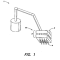
- Fig. 1 is a schematic diagram of a robot 1 manipulating a material handling tool 10 in accordance with the invention.
- the robot 1 may move the material handling tool 10 and allow needles 4 on the tool 10 to pick up and/or deposit material on one or more work areas, such as microtiter trays, gels containing separated DNA fragments or other biologic materials, etc.
- the robot 1 may move the tool 10 so that one or more needles 4 are appropriately positioned with respect to a microtiter tray and then actuate one or more needles 4 to remove material from, or deposit material in, wells in the microtiter tray.
- the needles may be actuated to perform other material handling operations, such as colony or plaque picking at the direction of a machine vision system.
- material handling operations such as colony or plaque picking at the direction of a machine vision system.
- the purposes and methods for such material handling are well known to those in the art and not described in detail herein.
- the robot 1 may be of any suitable typo or construction and may be capable of moving the tool 10 in any suitable number of degrees of freedom.
- the robot may be a gantry-type robot capable of moving the tool 10 in three degrees of freedom.
- other suitable robotic configurations capable of moving the tool 10 in one or more degrees of freedom may be used.
- the tool 10 and robot 1 may include a coupling to allow the robot 1 to exchange the tool 10 for other tools, thereby allowing the robot 1 to perform automated operations with different tools.
- the robot 1 or system controller may include a vision system or other suitable device to control positioning of needles 4 with respect to target areas, as is well known.
- a connection e.g., quick disconnect coupling, between the tool 10 and the robot 1 may provide physical support to the tool 10 as well as provide electrical power, control signals, a fluid supply or other fluid signal, etc.
- fluid refers to gases and/or liquids.
- the tool 10 includes a controller 2 that outputs signals to actuators in the controller that cause corresponding needles 4 to be actuated.
- actuation of a needle 4 may cause the needle 4 to move relative to the tool 10, such as extend away from the tool to pick or place material on a work area, control flow in the needle, such as drawing fluid into or expelling fluid out from the needle, or otherwise cause the needle to perform one or more material handling functions.
- the controller 2 and needles 4 are all mounted to a body 5 of the tool 10, but portions of the controller 2 may be located off the tool 10.
- the body 5 has a box-like shape
- the body 5 may be arranged in any suitable way.
- the needles 4 in this illustrative embodiment are arranged in a 5x4 array and extend from a bottom of the body 5, but any suitable number of needles 4 may be arranged in any suitable way on the body 5, e.g., to accommodate particular well patterns in a microtiter tray.
- the needles 4 may be arranged to receive removable pipette tips or other devices to handle materials, or may be arranged to handle materials directly.
- the controller 2 may provide any suitable signal or combination of signals to the actuators to actuate the needles 4.
- the controller 2 may provide electrical signals, magnetic signals, optical signals, fluid signals (e.g., changes in fluid pressure and/or flow), or combinations of such signals, such as providing both an electrical signal and a fluid signal to the actuators.
- signals provided by the controller 2 will depend upon the type of actuators.
- the actuators may be pneumatically-controlled fluid valves that open, close or otherwise change state based on a fluid signal.
- the actuators may include electrically-controlled fluid valves, relays, or other suitable devices to actuate a corresponding needle.
- the tool 10 may include one actuator for each needle, where each actuator includes a valve and associated pneumatic ram such that when the valve is open and air pressure is supplied through the open valve, the pneumatic ram may extend, and thereby extend a corresponding needle 4 from the body 5.
- the actuators may be responsive to two signals received from the controller 2 to actuate the needles 4. Having the actuators respond to two signals from the controller 2 may allow for matrix-type addressing of the actuators, as discussed in more detail below.
- the controller 2 may operate autonomously to actuate the needles 4 or operate at the direction of a higher level controller that is part of a material handling system. For example, the controller 2 may receive a signal to activate a particular needle or group of needles at a particular time and/or position of the tool 10, and generate and output appropriate signals to cause the desired actuation. The controller 2 may receive the signals in any suitable way, such as by wired and/or wireless link, and in any suitable format and/or communications protocol.
- the controller 2 and/or higher level controller may include any suitable general purpose data processing system, which can be, or include, a suitably programmed general purpose computer, or network of general purpose computers, and other associated devices, including communication devices, and/or other circuitry or components necessary to perform the desired input/output or other functions.
- the controllers can also be implemented at least in part as single special purpose integrated circuits (e.g., ASICs), or an array of ASICs, each having a main or central processor section for overall, system-level control and separate sections dedicated to performing various different specific computations, functions and other processes under the control of the central processor section.
- the controllers can also be implemented using a plurality of separate dedicated programmable integrated or other electronic circuits or devices, e.g., hardwired electronic or logic circuits, such as discrete element circuits or programmable logic devices.
- the controllers may also include other devices, such as an information display device, user input devices, such as a keyboard, user pointing device, touch screen or other user interface, data storage devices, communication devices or other electronic circuitry or components.
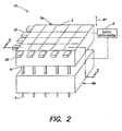
- Fig. 2 shows a perspective view of an embodiment of a tool 10 In accordance with the Invention.
- the controller 2 includes a 5x4 array of actuators 3 that are each associated with a corresponding needle 4.
- the corresponding needle 4 may be actuated, e.g., fluid flow in the needle may be controlled and/or the needle 4 may be moved relative to the body 5.
- the controller 2 includes four control switches 21 that are associated with actuators 3 in rows across the tool 10, and drive switches 22 that are associated with actuators 3 in columns on the tool 10.
- Control signals may be provided to the control switches 21 and drive switches 22 by a portion of the controller 2 (e.g., a data processor and associated memory) on the tool 10, or by another source off of the tool 10. Based on these control signals, the control switches 21 and drive switches 22 may provide suitable signals to the actuators 3 to actuate a particular needle or needles.
- the switches 21 and 22 may be any suitable device capable of responding to a control signal and providing a signal to corresponding actuators 3.
- the switches 21 and 22 may include electrically-controlled valves capable of switching an associated line between one or more fluid lines, e.g., sources of relatively high or low pressure, or sources of fluid flow. Pressure or other fluid flow sources may be provided to the switches 21 and 22 by lines (not shown) that lead to a pump, metering piston, reservoir or other devices off of the tool body 10.
- the actuators 3 in this illustrative embodiment are arranged in columns and rows, the actuators 3 may be logically grouped in any suitable way and in any suitable pattern.
- the tool 10 is not limited to a 5x4 array, but instead may have any suitable number of actuators and/or needles arranged in any suitable pattern, such as a pattern that allows the needles 4 to interact with standard 96-well, 384-well or other size/configuration microtiter trays or other material sample holders.
- the 5x4 array in this illustrative embodiment is used for simplicity and ease of reference, but should in no way be interpreted as being limiting of the invention in any way.
- the tool 10 also includes a drive mechanism 9 that is capable of moving an upper portion 5a of the body 5 relative to the lower portion 5b, e.g., in a direction shown by the arrow 91. Such movement may cause plungers 6 secured to the upper portion 5a to move relative to the lower portion 5b and create suction/pressure for each of the needles 4 to aspirate/dispense a sample.
- the drive mechanism 9 may take any suitable form as is well known in the art.
- the drive mechanism 9 may include guideways for guiding the movement of the upper portion 5a relative to the bottom portion 5b, a linear motor that provides the motive force to move the upper portion 5a, and a linear encoder that provides position feedback so the upper portion 5a may be positioned accurately relative to the bottom portion 5b.
- the upper portion is moved relative to the bottom portion 5b
- the bottom portion 5b may be moved relative to the upper portion 5a.
- the tool body 5 may have more than two portions, e.g., the tool 10 may include an intermediate portion between the upper and lower portions, and the various portions may be moved relative to each other in any suitable way.
- the tool 5 need not have movable portions like that shown, and instead the needles 4 may be actuated using other mechanisms.
- Fig. 3 shows a schematic cross-sectional view of the tool 10 shown in Fig. 2 .
- the plungers 6 are secured at a top end to the upper portion 5a of the tool body 5 and move up and down in the direction shown by arrow 91 when the upper portion 5a is driven by the drive mechanism 9. This causes the plungers 6 to move relative to the lower portion 5b in a corresponding channel 7, e.g., a cylindrical bore in the lower portion 5b.
- the seal(s) 8 may be stationary relative to the channel 7, or move with the plunger in the channel wall.
- the seal created may be enhanced by the use of a suitable lubricant or other material on the plunger 6. Movement of the plungers 6 in their respective channels 7 can create a suction/pressure at a corresponding needle 4, e.g., so a liquid can be aspirated or dispensed, as is well known in the art.
- the needles 4 may carry a replaceable pipette tip 41 as is known in the art.
- the plungers 6 are porous, e.g., the plungers 6 have a hole or passageway that extends through the length of the plungers 6.
- the passageway allows fluid (gas or liquid) to pass through the plunger 6.
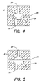
- the passageways for each plunger 6 communicate with an actuator 3, e.g., a membrane valve as shown in Fig. 3 , via a line 32.
- the actuators 3 may open or close the passageways by operation of the membrane valve.
- a suitable control signal e.g., fluid pressure
- the flexible member 31 may deform and prevent communication between the line 32 and a line 24.
- a suitable control signal e.g., fluid pressure
- the flexible member 31 may retract, allowing communication between the line 32 and the line 24.
- the passageways may be opened or closed by the valves.
- a closed passageway allows a plunger 6 to create a suction/pressure in the channel 7 when the plunger 6 moves.
- an open passageway may prevent a suction/pressure from being created by movement of the plunger 6 since fluid may be supplied from the line 24 to the plunger passageway. That is, the line 24 may be open to ambient air pressure or supplied with a fluid at a suitable pressure to prevent movement of the plunger from causing the needle to aspirate/dispense a sample.
- Control of the action at the needles 4 may be further controlled by controlling the fluid in the line 24.
- the line 24 may be open to ambient air pressure so that opening and closing of the actuators 3 effectively closes or opens the passageway.
- fluid may be supplied under pressure to the line 24, e.g., so that a liquid or gas may be selectively supplied through an open valve, through the plunger 6 and expelled from the corresponding needle.
- a vacuum may also be applied to the lines 24 so that when a passageway is opened by an actuator 3, fluid may be aspirated by a selected needle without requiring movement of plungers 6.
- aspirating/dispensing samples from needles 4 may be controlled by controlling fluid flow through the passageways independent of, or in conjunction with, movement of the plungers 6.
- Switching of fluid flow to the lines 23 and 24 may be controlled by the switches 21 and 22, respectively.
- the switches 21 and 22 may be electrically operated valves that switch the lines 23 and 24 between one or more fluid supply lines, e.g., lines that provide a vacuum, fluid under pressure or ambient air pressure.
- the membrane valves shown are only one way that an actuator 3 for controlling the passageways may be implemented.
- the actuators 3 may include two or more membrane valves in a cascaded arrangement to allow truly individual control of the passageways, and of course other types of valves or other devices may be used to open or close the passageways. Of course, individually controlled valves could be used to open or close each passageway rather than using the matrix type valve arrangement shown.
- Fig. 6 shows a schematic plan view of the upper portion 5a of the tool 10.
- the lines 23 provide control signals to rows A-D of actuators 3 via a corresponding switch 21.
- Drive signals are provided to columns 1-5 of actuators 3 via a corresponding switch 22.
- each control switch 21 provides a control signal approximately simultaneously to all actuators 3 in the corresponding row via a control line 23.
- the control signal provided to a row of actuators 3 may cause the actuators 3 to change state between an open and closed state.
- each of the drive switches 22 may approximately simultaneously provide a drive signal to all actuators 3 in a corresponding column along a drive line 24.
- individual passageways may be addressed, e.g., opened or closed, by providing a control signal along the actuator's corresponding control line 23, and a drive signal along the actuator's corresponding drive line 24 may control the actuation of the needle.
- the passageway corresponding to the actuator 3 in the top right corner of the tool 10 as shown in Fig. 3 (position A-5) may be opened by providing a control signal from the control switch 21 for row A suitable to open the valve and allow flow through the passageway.
- Flow through the passageway may be controlled by controlling flow through the lines 24.
- valve for the passageway at position A-5 is opened, if flow is not allowed in the line 24 for that valve, e.g., the switch 22 for column 5 prevents flow in the line 24, fluid will not flow in the passageway.
- flow for the passageway may be controlled by controlling flow in the lines 24 as well.
- individual needles 4 may be actuated by providing appropriate signals to the lines 23 and 24, e.g., rows and/or columns, of actuators in the tool 10.
- selected groups of actuators 3 may be addressed by providing appropriate signals along the rows A-D and columns 1-5.
- all needles on the tool 10, or selected needles, in a particular row or column may be approximately simultaneously actuated in a similar way, e.g., all of the actuators 3 in row A may aspirate a liquid by providing an appropriate control signal from the control switch 21 for row A to close the valves in the row A, providing appropriate control signals from the switches 21 for rows B-D to open the valves in rows B-D, and providing appropriate drive signals from the drive switches 22 for columns 1-5 to allow flow through the lines 24 while the plungers 6 are moved upwardly by the drive mechanism 9.
- Such a set of control signals may allow only the needles in row A to aspirate/dispense a sample. It will be appreciated that other selected groups of needles may be approximately simultaneously actuated by providing signals on appropriate control and drive lines 23 and 24 and/or moving the plungers 6 appropriately by the drive mechanism 9.
- the plungers 6 and upper and lower portions 5a and 5b may be made of any suitable material(s), such as plastic, glass or suitable metal, and the channels, lines, chambers and other features may be formed in any suitable way using any suitable process.
- the upper and lower portions 5a and 5b may be made of multiple layers of plastic material that have grooves, channels or are otherwise formed to create the desired lines, channels, etc. in the tool body 10. These layers may be joined together, e.g., by heating the layers and pressing them together, to form a unitary block.
- the membrane valves 31 may be formed by positioning a flexible member 6, such as a sheet of silicone rubber, between the layers of the upper portion 5a and securing the layers. The construction of membrane valves is well known, and alternate methods of construction will be appreciated by those of skill in the art.
- the control and drive signals may also cause the membrane valves to perform other actuation operations with respect to the needles, such as pumping fluid through a corresponding needle and/or drawing or expelling a metered amount of fluid into or out of a corresponding needle 4.
- Pumping and metering operations may be performed by, for example, moving the flexible member in a valve to a closed state, closing a drive line 24 for the valve at a drive switch 22, and moving the flexible member in the valve to an open state, thereby causing fluid to be drawn into the needle 4. Movement of the flexible member may be closely controlled to perform accurate fluid metering through the valve's needle, e.g., by controlling the amount of fluid drawn from the valve by the control line 23.
- Such control can be performed by a metering piston coupled to the control line 23 or drive line 24, by accurately timing the opening and closing of a valve in the control switch 21 while supplying a constant fluid flow through the valve, or other means as will be appreciated by those of skill in the art.
- control and drive switches in this illustrative embodiment control fluid flow to corresponding rows and columns of valves
- the switches may provide other signal types to the actuators, such as electrical, optical, magnetic and other signal types.
- the actuators and/or valves in this embodiment may include or be replaced with any other suitable element(s), such as electrical or optical relays, transistors, optical valves, etc.
- the actuators 3 may include other drive elements, such as hydraulic rams, solenoid actuators, motors, and so on. Therefore, any suitable arrangement of elements may be used as actuators to receive control and drive signals and actuate a corresponding needle.
Landscapes
- Health & Medical Sciences (AREA)
- Chemical & Material Sciences (AREA)
- Clinical Laboratory Science (AREA)
- Chemical Kinetics & Catalysis (AREA)
- General Health & Medical Sciences (AREA)
- Pathology (AREA)
- Analytical Chemistry (AREA)
- Biochemistry (AREA)
- Physics & Mathematics (AREA)
- General Physics & Mathematics (AREA)
- Immunology (AREA)
- Life Sciences & Earth Sciences (AREA)
- Automatic Analysis And Handling Materials Therefor (AREA)
- Sampling And Sample Adjustment (AREA)
- Separation Using Semi-Permeable Membranes (AREA)
- Materials For Medical Uses (AREA)
- Devices For Use In Laboratory Experiments (AREA)
- Feeding, Discharge, Calcimining, Fusing, And Gas-Generation Devices (AREA)
Claims (12)
- Materialhandhabungswerkzeug umfassend:einen Werkzeugkörper (5);mehrere Nadeln (4), die an dem Werkzeugkörper angebracht sind, wobei jede der mehreren Nadeln aufgebaut und eingerichtet ist, Material von einem Arbeitsbereich zu entfernen und Material an einem Arbeitsbereich abzusetzen;mehrere Kolben (6), die in dem Werkzeugkörper bewegbar sind, wobei jeder der mehreren Kolben zu einer entsprechenden der mehreren Nadeln gehört und jeder der Kolben einen Durchlass aufweist, der Fluidfluss durch den Kolben ermöglicht; undeine Steuereinrichtung (2), die aufgebaut und eingerichtet ist, jeden der Durchlässe einzeln anzuwählen, so dass ein Fluss in jedem der Durchlässe einzeln gesteuert ist, wobei die Steuereinrichtung mehrere Aktuatoren (3) umfasst und jeder der Aktuatoren geeignet ist, einen entsprechenden Durchlass zu öffnen und zu schließen.
- Werkzeug nach Anspruch 1, bei dem jeder der mehreren Aktuatoren (3) ein Membranventil beinhaltet, das den Fluidfluss mit Bezug auf einen entsprechenden Durchlass steuert.
- Werkzeug nach Anspruch 1 oder 2, bei dem die Steuereinrichtung mehrere Steuerschalter (21, 22) umfasst, welche die mehreren Aktuatoren mit Signalen versorgen, um die entsprechenden Durchlässe zu öffnen und zu schließen.
- Werkzeug nach Anspruch 3, bei dem jeder der mehreren Steuerschalter ein Ventil umfasst, das einen entsprechenden Aktuator mit einem Fluidsignal versorgt.
- Werkzeug nach Anspruch 1, bei dem die Steuereinrichtung mehrere Antriebsschalter (22) umfasst, die den Fluss durch einen durch einen Aktuator geöffneten Durchlass steuern.
- Werkzeug nach Anspruch 5, bei dem jeder der mehreren Antriebsschalter (22) ein Ventil beinhaltet, das einen Fluidfluss für einen entsprechenden Durchlass vorsieht.
- Werkzeug nach einem der Ansprüche 1 bis 6, bei dem das Schließen des Durchlasses eines Kolbens entweder zu einem Saugen von Fluid in eine entsprechende Nadel oder zu einem Ausstoßen von Fluid aus einer entsprechenden Nadel führt, wenn der Kolben in dem Werkzeugkörper bewegt wird.
- Werkzeug nach einem der Ansprüche 1 bis 7, bei dem ein Abschnitt jedes Kolbens an einem ersten Abschnitt (5a) des Werkzeugkörpers befestigt ist und ein zweiter Abschnitt jedes Kolbens so verschiebbar mit einem Kanal in einem zweiten Abschnitt (5b) des Werkzeugkörpers in Eingriff ist, dass eine Bewegung des ersten Abschnitts des Werkzeugkörpers relativ zu dem zweiten Abschnitt des Werkzeugkörpers eine Druckänderung in jedem Kanal für Kolben, die ihren Durchlass geschlossen haben, bewirkt.
- Werkzeug nach Anspruch 2, bei dem die Steuereinrichtung eingerichtet ist, die Membranventile zu steuern, um gleichzeitig den Fluss für mehrere Durchlässe zu steuern.
- Werkzeug nach einem der Ansprüche 1 bis 9, bei dem die mehreren Nadeln an dem Werkzeugkörper in M Spalten und N Reihen angebracht sind und die Steuereinrichtung beinhaltet:mehrere Anwählventile, wobei zu jedem Durchlass wenigstens ein Anwählventil gehört, das den Fluss für den Durchlass steuert; undmehrere Schalter, welche die Anwählventile mit Signalen versorgen, wobei die Anzahl von Schaltern gleich M+N ist;wobei die mehreren Schalter eingerichtet sind, die Anwählventile mit Signalen zu versorgen, um für jede Nadel den Fluss einzeln zu steuern.
- Werkzeug nach Anspruch 10, bei dem die mehreren Schalter an dem Werkzeugkörper angebracht sind.
- Werkzeug nach Anspruch 10 oder 11, bei dem die mehreren Schalter M Schalter beinhalten, die zu M Spalten von Nadeln gehören, wobei jeder der M Schalter Ventilen für eine entsprechende Spalte entspricht und diese mit Signalen versorgt, und die mehreren Schalter ferner N Schalter beinhalten, die zu N Reihen von Nadeln gehören, wobei jeder der N Schalter Ventilen für eine entsprechende Reihe entspricht und diese mit Signalen versorgt.
Applications Claiming Priority (3)
| Application Number | Priority Date | Filing Date | Title |
|---|---|---|---|
| US39798902P | 2002-07-23 | 2002-07-23 | |
| US397989P | 2002-07-23 | ||
| PCT/US2003/022376 WO2004009238A1 (en) | 2002-07-23 | 2003-07-18 | Liquid handling tool having hollow plunger |
Publications (2)
| Publication Number | Publication Date |
|---|---|
| EP1539352A1 EP1539352A1 (de) | 2005-06-15 |
| EP1539352B1 true EP1539352B1 (de) | 2009-12-23 |
Family
ID=30771160
Family Applications (1)
| Application Number | Title | Priority Date | Filing Date |
|---|---|---|---|
| EP03765666A Expired - Lifetime EP1539352B1 (de) | 2002-07-23 | 2003-07-18 | Flüssigkeitshandhabungsinstrument mit einem hohlen kolben |
Country Status (8)
| Country | Link |
|---|---|
| US (1) | US7438857B2 (de) |
| EP (1) | EP1539352B1 (de) |
| JP (1) | JP4317816B2 (de) |
| AT (1) | ATE452704T1 (de) |
| AU (1) | AU2003251996A1 (de) |
| DE (1) | DE60330681D1 (de) |
| DK (1) | DK1539352T3 (de) |
| WO (1) | WO2004009238A1 (de) |
Families Citing this family (72)
| Publication number | Priority date | Publication date | Assignee | Title |
|---|---|---|---|---|
| US6692700B2 (en) | 2001-02-14 | 2004-02-17 | Handylab, Inc. | Heat-reduction methods and systems related to microfluidic devices |
| US6852287B2 (en) | 2001-09-12 | 2005-02-08 | Handylab, Inc. | Microfluidic devices having a reduced number of input and output connections |
| US7010391B2 (en) | 2001-03-28 | 2006-03-07 | Handylab, Inc. | Methods and systems for control of microfluidic devices |
| US7829025B2 (en) | 2001-03-28 | 2010-11-09 | Venture Lending & Leasing Iv, Inc. | Systems and methods for thermal actuation of microfluidic devices |
| US8895311B1 (en) | 2001-03-28 | 2014-11-25 | Handylab, Inc. | Methods and systems for control of general purpose microfluidic devices |
| US7249529B2 (en) * | 2003-03-28 | 2007-07-31 | Protedyne Corporation | Robotically manipulable sample handling tool |
| WO2005011867A2 (en) | 2003-07-31 | 2005-02-10 | Handylab, Inc. | Processing particle-containing samples |
| US8852862B2 (en) * | 2004-05-03 | 2014-10-07 | Handylab, Inc. | Method for processing polynucleotide-containing samples |
| US7246551B2 (en) * | 2004-07-09 | 2007-07-24 | Protedyne Corporation | Liquid handling device with surface features at a seal |
| US7637175B1 (en) | 2004-08-26 | 2009-12-29 | Elemental Scientific, Inc. | Automated sampling device |
| US7690275B1 (en) | 2004-08-26 | 2010-04-06 | Elemental Scientific, Inc. | Automated sampling device |
| US7201072B1 (en) | 2004-08-26 | 2007-04-10 | Elemental Scientific Inc. | Automated sampling device |
| DE102005014572B4 (de) * | 2005-03-31 | 2007-01-04 | Eppendorf Ag | Pipettiervorrichtung |
| US7597520B2 (en) | 2005-05-24 | 2009-10-06 | Festo Corporation | Apparatus and method for transferring samples from a source to a target |
| US7534081B2 (en) | 2005-05-24 | 2009-05-19 | Festo Corporation | Apparatus and method for transferring samples from a source to a target |
| JP2007232524A (ja) * | 2006-02-28 | 2007-09-13 | Universal Bio Research Co Ltd | タンパク質等溶液ろ過処理方法およびその装置 |
| US10900066B2 (en) | 2006-03-24 | 2021-01-26 | Handylab, Inc. | Microfluidic system for amplifying and detecting polynucleotides in parallel |
| US7998708B2 (en) | 2006-03-24 | 2011-08-16 | Handylab, Inc. | Microfluidic system for amplifying and detecting polynucleotides in parallel |
| US11806718B2 (en) | 2006-03-24 | 2023-11-07 | Handylab, Inc. | Fluorescence detector for microfluidic diagnostic system |
| DK3088083T3 (en) | 2006-03-24 | 2018-11-26 | Handylab Inc | Method of carrying out PCR down a multi-track cartridge |
| JP2009534688A (ja) * | 2006-04-24 | 2009-09-24 | プロテダイン・コーポレーション | 自律的に作動するツールを備えているロボットシステム |
| WO2008060604A2 (en) | 2006-11-14 | 2008-05-22 | Handylab, Inc. | Microfluidic system for amplifying and detecting polynucleotides in parallel |
| US8709787B2 (en) | 2006-11-14 | 2014-04-29 | Handylab, Inc. | Microfluidic cartridge and method of using same |
| US7799281B2 (en) | 2007-01-16 | 2010-09-21 | Festo Corporation | Flux concentrator for biomagnetic particle transfer device |
| DE102007005323A1 (de) * | 2007-01-29 | 2008-07-31 | Bioplan Consulting Gmbh | Absaugeinrichtung |
| EP2006020B1 (de) * | 2007-06-15 | 2011-09-28 | Hamilton Bonaduz AG | Probenbehandlungsanordnung für eine Flüssigkeitsdosiervorrichtung |
| JP4959450B2 (ja) * | 2007-07-10 | 2012-06-20 | 株式会社日立ハイテクノロジーズ | 化学分析装置 |
| US8133671B2 (en) | 2007-07-13 | 2012-03-13 | Handylab, Inc. | Integrated apparatus for performing nucleic acid extraction and diagnostic testing on multiple biological samples |
| US8182763B2 (en) | 2007-07-13 | 2012-05-22 | Handylab, Inc. | Rack for sample tubes and reagent holders |
| US9186677B2 (en) | 2007-07-13 | 2015-11-17 | Handylab, Inc. | Integrated apparatus for performing nucleic acid extraction and diagnostic testing on multiple biological samples |
| AU2008276211B2 (en) | 2007-07-13 | 2015-01-22 | Handylab, Inc. | Polynucleotide capture materials, and methods of using same |
| US8287820B2 (en) | 2007-07-13 | 2012-10-16 | Handylab, Inc. | Automated pipetting apparatus having a combined liquid pump and pipette head system |
| US9618139B2 (en) | 2007-07-13 | 2017-04-11 | Handylab, Inc. | Integrated heater and magnetic separator |
| US8105783B2 (en) | 2007-07-13 | 2012-01-31 | Handylab, Inc. | Microfluidic cartridge |
| US8016260B2 (en) | 2007-07-19 | 2011-09-13 | Formulatrix, Inc. | Metering assembly and method of dispensing fluid |
| CA3138078C (en) | 2007-10-02 | 2024-02-13 | Labrador Diagnostics Llc | Modular point-of-care devices and uses thereof |
| USD787087S1 (en) | 2008-07-14 | 2017-05-16 | Handylab, Inc. | Housing |
| FI20085815A7 (fi) * | 2008-09-02 | 2010-03-03 | Wallac Oy | Laitteisto, järjestelmä ja menetelmä nestemäisten näytteiden suodattamiseksi |
| US8100293B2 (en) * | 2009-01-23 | 2012-01-24 | Formulatrix, Inc. | Microfluidic dispensing assembly |
| EP2566618B8 (de) * | 2010-05-03 | 2014-07-09 | Integra Biosciences AG | Unbeabsichtigte bewegungs regler für manuell-gesteuerten multi-kanal elektronischen pipetten |
| JP5400251B2 (ja) * | 2010-05-03 | 2014-01-29 | インテグラ バイオサイエンシズ コープ. | 手動で配向されるマルチチャネル用電子式ピペットチップの位置決め |
| EP2577320B1 (de) | 2010-06-04 | 2019-04-17 | Parker-Hannificn Corporation | Miniatur-spritzenpumpensystem und module |
| DE102010041833B4 (de) * | 2010-09-30 | 2014-05-15 | INSTITUT FüR MIKROTECHNIK MAINZ GMBH | Mikrofluidikchip mit mehreren Zylinder-Kolben-Anordnungen |
| MX349288B (es) | 2011-01-21 | 2017-07-21 | Theranos Inc | Sistemas y metodos para maximizacion de uso de muestras. |
| WO2012103005A2 (en) * | 2011-01-24 | 2012-08-02 | Cornell University | Deposition of materials for edible solid freeform fabrication |
| ES2769028T3 (es) | 2011-04-15 | 2020-06-24 | Becton Dickinson Co | Termociclador microfluídico de barrido en tiempo real |
| JP5709678B2 (ja) * | 2011-07-14 | 2015-04-30 | パナソニックヘルスケアホールディングス株式会社 | 分注装置 |
| US8475739B2 (en) | 2011-09-25 | 2013-07-02 | Theranos, Inc. | Systems and methods for fluid handling |
| US20140170735A1 (en) | 2011-09-25 | 2014-06-19 | Elizabeth A. Holmes | Systems and methods for multi-analysis |
| US9664702B2 (en) | 2011-09-25 | 2017-05-30 | Theranos, Inc. | Fluid handling apparatus and configurations |
| US9632102B2 (en) | 2011-09-25 | 2017-04-25 | Theranos, Inc. | Systems and methods for multi-purpose analysis |
| US9619627B2 (en) | 2011-09-25 | 2017-04-11 | Theranos, Inc. | Systems and methods for collecting and transmitting assay results |
| US8840838B2 (en) | 2011-09-25 | 2014-09-23 | Theranos, Inc. | Centrifuge configurations |
| US8435738B2 (en) | 2011-09-25 | 2013-05-07 | Theranos, Inc. | Systems and methods for multi-analysis |
| US9268915B2 (en) | 2011-09-25 | 2016-02-23 | Theranos, Inc. | Systems and methods for diagnosis or treatment |
| US10012664B2 (en) | 2011-09-25 | 2018-07-03 | Theranos Ip Company, Llc | Systems and methods for fluid and component handling |
| US9250229B2 (en) | 2011-09-25 | 2016-02-02 | Theranos, Inc. | Systems and methods for multi-analysis |
| US9810704B2 (en) | 2013-02-18 | 2017-11-07 | Theranos, Inc. | Systems and methods for multi-analysis |
| USD692162S1 (en) | 2011-09-30 | 2013-10-22 | Becton, Dickinson And Company | Single piece reagent holder |
| ES2645966T3 (es) | 2011-09-30 | 2017-12-11 | Becton, Dickinson And Company | Tira reactiva unificada |
| US20140297029A1 (en) * | 2011-10-28 | 2014-10-02 | Hewlett-Packard Developement Company, L.P. | Parallel addressing method |
| CN104040238B (zh) | 2011-11-04 | 2017-06-27 | 汉迪拉布公司 | 多核苷酸样品制备装置 |
| US8802030B2 (en) * | 2012-02-01 | 2014-08-12 | Cybio Ag | Capillary dispenser |
| AU2013214849B2 (en) | 2012-02-03 | 2016-09-01 | Becton, Dickinson And Company | External files for distribution of molecular diagnostic tests and determination of compatibility between tests |
| US9341229B1 (en) | 2012-09-10 | 2016-05-17 | Elemental Scientific, Inc. | Automated sampling device |
| CN103114035B (zh) * | 2013-03-14 | 2014-04-02 | 东南大学 | 一种全封闭提取、转移和贮存核酸的装置 |
| JP2015190947A (ja) * | 2014-03-28 | 2015-11-02 | 東ソー株式会社 | 試料吸引装置 |
| US9702793B2 (en) | 2015-03-16 | 2017-07-11 | Todd A Balisky | Variable volume sample capture device |
| ES2891850T3 (es) * | 2015-11-25 | 2022-01-31 | Siemens Healthcare Diagnostics Products Gmbh | Procedimiento para la transferencia de un volumen de líquido en un dispositivo de análisis |
| DE102016015700A1 (de) * | 2016-12-21 | 2018-06-21 | Bayer Pharma Aktiengesellschaft | Dosiervorrichtung |
| US20240123441A1 (en) * | 2021-02-15 | 2024-04-18 | University Of South Florida | Systems and methods for dispensing liquids |
| EP4388295A1 (de) * | 2021-12-29 | 2024-06-26 | Andrew Alliance S.A. | Probenextraktionssystem und -verfahren |
Family Cites Families (52)
| Publication number | Priority date | Publication date | Assignee | Title |
|---|---|---|---|---|
| US3290946A (en) | 1964-05-25 | 1966-12-13 | Dow Chemical Co | Pipetting device |
| US3572552A (en) * | 1969-07-25 | 1971-03-30 | Perry W Guinn | Diaphragm dispenser |
| US3656351A (en) | 1970-06-25 | 1972-04-18 | Bio Data Corp | Pipette |
| US3855868A (en) * | 1972-02-10 | 1974-12-24 | O Sudvaniemi | Multiple pipette |
| US3760639A (en) | 1972-10-20 | 1973-09-25 | Bio Data Corp | Pipette assembly |
| SE381577B (sv) | 1974-06-24 | 1975-12-15 | Mediplast Ab | Anordning for overforing av en vetska, sasom blod fran en cylindrisk behallare till en pipett |
| US4052161A (en) | 1974-08-22 | 1977-10-04 | The Perkin-Elmer Corporation | Kinetic analyzer |
| FR2287941A1 (fr) | 1974-10-15 | 1976-05-14 | Marteau D Autry Eric | Dispositif d'ejection de l'embout amovible d'une pipette |
| US3945254A (en) | 1974-12-16 | 1976-03-23 | Becton, Dickinson And Company | Multiple shot pipetter |
| US3954014A (en) | 1974-12-16 | 1976-05-04 | Becton, Dickinson And Company | Multiple shot pipetter |
| US4099548A (en) | 1976-08-25 | 1978-07-11 | Oxford Laboratories Inc. | Hand-held pipette for repetitively dispensing precise volumes of liquid |
| US4237095A (en) | 1978-04-25 | 1980-12-02 | Kommandiittiyhtio Finnpipette Osmo A. Suovaniemi | Tip vessel for use in connection with a dosage pipette |
| FI59343C (fi) | 1979-01-23 | 1981-08-10 | Suovaniemi Finnpipette | Flerdospipett |
| US4294125A (en) | 1980-04-24 | 1981-10-13 | Lee Tsao Piao | Pipette controller with graduate reading plunger and lever assembly for gravity drainage |
| US4599220A (en) | 1982-02-16 | 1986-07-08 | Yonkers Edward H | Multi-channel pipetter |
| US4555957A (en) | 1983-10-14 | 1985-12-03 | Cetus Corporation | Bi-directional liquid sample handling system |
| US4567780A (en) | 1984-03-12 | 1986-02-04 | American Hospital Supply Corporation | Hand-held pipette with disposable capillary |
| DE3641593A1 (de) | 1985-12-06 | 1987-06-11 | Fuji Photo Film Co Ltd | Doppelpipettenvorrichtung |
| US4810348A (en) | 1987-03-16 | 1989-03-07 | Helena Laboratories Corporation | Automatic electrophoresis apparatus and method |
| US5055263A (en) * | 1988-01-14 | 1991-10-08 | Cyberlab, Inc. | Automated pipetting system |
| WO1989010191A1 (fr) | 1988-04-18 | 1989-11-02 | Buergisser Ernst | Dispositif de pipettage |
| FI86968C (fi) | 1990-05-04 | 1992-11-10 | Biohit Oy | Pipett |
| US5525302A (en) | 1991-02-01 | 1996-06-11 | Astle; Thomas W. | Method and device for simultaneously transferring plural samples |
| FI86969C (fi) | 1991-02-05 | 1992-11-10 | Biohit Oy | Pipett |
| US5670113A (en) | 1991-12-20 | 1997-09-23 | Sibia Neurosciences, Inc. | Automated analysis equipment and assay method for detecting cell surface protein and/or cytoplasmic receptor function using same |
| WO1993025914A1 (en) | 1992-06-08 | 1993-12-23 | Behring Diagnostics, Inc. | Liquid dispensing system |
| FR2696110B1 (fr) | 1992-09-28 | 1994-12-09 | Gilson Medical Electronics Sa | Perfectionnement à une piquette de prélèvement et de distribution de volumes réglables de liquides. |
| US5381699A (en) | 1992-10-06 | 1995-01-17 | Health Research, Inc. | Radon collector and bubbler |
| US5370843A (en) | 1993-09-13 | 1994-12-06 | Asi Instruments, Inc. | Pipette puller |
| FR2723700B1 (fr) | 1994-08-16 | 1996-11-15 | Marteau D Autry Eric | Pipette pour distribuer des volumes successifs de liquide |
| US5614153A (en) | 1995-05-26 | 1997-03-25 | Rainin Instrument Co., Inc. | Pipette tip ejector |
| US5700959A (en) | 1995-07-14 | 1997-12-23 | Rainin Instrument Co., Inc. | Manual pipette with magnet assist |
| US5792424A (en) | 1996-03-05 | 1998-08-11 | Rainin Instrument Co., Inc. | Manual pipette with delayed-action home position latch |
| AU733643B2 (en) | 1996-09-09 | 2001-05-17 | Tyco Group S.A.R.L. | Electronically monitored mechanical pipette |
| US6019004A (en) | 1996-09-10 | 2000-02-01 | Sherwood Services, Ag | Detachable pipette barrel |
| US5983733A (en) | 1996-11-15 | 1999-11-16 | Hamilton Company | Manual pipette |
| US6123905A (en) | 1997-01-17 | 2000-09-26 | Matrix Technologies Corporation | Pipettor including an indicator and method of use |
| US5985214A (en) | 1997-05-16 | 1999-11-16 | Aurora Biosciences Corporation | Systems and methods for rapidly identifying useful chemicals in liquid samples |
| US5964381A (en) | 1997-11-12 | 1999-10-12 | Ljl Biosystems, Inc. | Device for projectile dispensing of small volume liquid samples |
| WO1999032870A1 (en) | 1997-12-23 | 1999-07-01 | Rainin Instrument Co., Inc. | Manual pipette with magnet assist |
| US6033911A (en) * | 1998-02-27 | 2000-03-07 | Hamilton Company | Automated assaying device |
| US6235002B1 (en) * | 1998-04-17 | 2001-05-22 | Cdc Technologies, Inc. | Syringe for use in fluid-handling apparatus |
| WO2000013609A2 (en) | 1998-09-02 | 2000-03-16 | Langerhans Aps | Apparatus for isolation of particles, preferably cell clusters |
| DE19845950C1 (de) | 1998-10-06 | 2000-03-23 | Eppendorf Geraetebau Netheler | Pipettiersystem mit einer Pipettiervorrichtung und mindestens einer daran lösbar befestigten Pipettenspitze |
| EP1129346A2 (de) | 1998-10-16 | 2001-09-05 | Intelligent Automation Systems | Automatisierter arbeitsplatz zur kontinuierlichen behandlung |
| US6248295B1 (en) | 1998-11-06 | 2001-06-19 | Rainin Instrument Co., Inc. | Pipette with improved pipette tip and mounting shaft combination |
| US6168761B1 (en) | 1998-11-06 | 2001-01-02 | Rainin Instrument Co., Inc. | Pipette with improved pipette tip and mounting shaft |
| US6197259B1 (en) | 1998-11-06 | 2001-03-06 | Rainin Instrument Co., Inc. | Easy eject pipette tip |
| US6258324B1 (en) | 1999-03-15 | 2001-07-10 | Felix H. Yiu | Pipette dispensing block |
| US6244119B1 (en) | 1999-08-03 | 2001-06-12 | Wallac Oy | Multichannel pipette system and pipette tips therefor |
| FR2801108B1 (fr) | 1999-11-16 | 2002-03-01 | Maxmat S A | Analyseur chimique ou biochimique a regulation de la temperature reactionnelle |
| US6365110B1 (en) | 2000-03-09 | 2002-04-02 | Rainin Instrument | Blowout springless manual air displacement pipette with mechanical assist for aiding in locating and maintaining pipette plunger at a home position |
-
2003
- 2003-07-18 EP EP03765666A patent/EP1539352B1/de not_active Expired - Lifetime
- 2003-07-18 DE DE60330681T patent/DE60330681D1/de not_active Expired - Lifetime
- 2003-07-18 US US10/622,414 patent/US7438857B2/en not_active Expired - Fee Related
- 2003-07-18 AT AT03765666T patent/ATE452704T1/de not_active IP Right Cessation
- 2003-07-18 AU AU2003251996A patent/AU2003251996A1/en not_active Abandoned
- 2003-07-18 DK DK03765666.7T patent/DK1539352T3/da active
- 2003-07-18 WO PCT/US2003/022376 patent/WO2004009238A1/en not_active Ceased
- 2003-07-18 JP JP2004523509A patent/JP4317816B2/ja not_active Expired - Fee Related
Also Published As
| Publication number | Publication date |
|---|---|
| EP1539352A1 (de) | 2005-06-15 |
| AU2003251996A1 (en) | 2004-02-09 |
| US7438857B2 (en) | 2008-10-21 |
| US20040018119A1 (en) | 2004-01-29 |
| WO2004009238A1 (en) | 2004-01-29 |
| JP2005534015A (ja) | 2005-11-10 |
| ATE452704T1 (de) | 2010-01-15 |
| DK1539352T3 (da) | 2010-04-19 |
| JP4317816B2 (ja) | 2009-08-19 |
| DE60330681D1 (de) | 2010-02-04 |
Similar Documents
| Publication | Publication Date | Title |
|---|---|---|
| EP1539352B1 (de) | Flüssigkeitshandhabungsinstrument mit einem hohlen kolben | |
| US7125727B2 (en) | Sample handling tool with piezoelectric actuator | |
| EP1493036B1 (de) | Robotisch manipulierbares proben-verarbeitungswerkzeug | |
| US6824024B2 (en) | Device for the take-up and/or release of liquid samples | |
| US6506611B2 (en) | Metering head for parallel processing of a plurality of fluid samples | |
| US6672344B1 (en) | Robotic system having positionally adjustable multiple probes | |
| CN100578228C (zh) | 一种微量液体精密分配仪器及其使用方法 | |
| EP1206321B1 (de) | Flexibler pipetten-streifen und zugehöriges anwendungsverfahren | |
| JP2002214244A (ja) | 液体サンプルを吸入し分配する装置 | |
| US7249529B2 (en) | Robotically manipulable sample handling tool | |
| EP1542837A1 (de) | Mit einem roboter handhabbares werkzeug mit bordprozessor | |
| EP1663494B1 (de) | Verfahren und vorrichtung zur handhabung von kleinvolumigen fluidproben | |
| JP4169693B2 (ja) | 液体ハンドリングシステムのための2次液体ディスペンシングモジュール | |
| JP2003149255A (ja) | 直交座標および円筒座標に移動可能な分注装置 | |
| WO2003023410A1 (en) | Secondary liquid dispensing module for liquid handling system |
Legal Events
| Date | Code | Title | Description |
|---|---|---|---|
| PUAI | Public reference made under article 153(3) epc to a published international application that has entered the european phase |
Free format text: ORIGINAL CODE: 0009012 |
|
| 17P | Request for examination filed |
Effective date: 20050211 |
|
| AK | Designated contracting states |
Kind code of ref document: A1 Designated state(s): AT BE BG CH CY CZ DE DK EE ES FI FR GB GR HU IE IT LI LU MC NL PT RO SE SI SK TR |
|
| AX | Request for extension of the european patent |
Extension state: AL LT LV MK |
|
| DAX | Request for extension of the european patent (deleted) | ||
| GRAP | Despatch of communication of intention to grant a patent |
Free format text: ORIGINAL CODE: EPIDOSNIGR1 |
|
| GRAS | Grant fee paid |
Free format text: ORIGINAL CODE: EPIDOSNIGR3 |
|
| GRAA | (expected) grant |
Free format text: ORIGINAL CODE: 0009210 |
|
| AK | Designated contracting states |
Kind code of ref document: B1 Designated state(s): AT BE BG CH CY CZ DE DK EE ES FI FR GB GR HU IE IT LI LU MC NL PT RO SE SI SK TR |
|
| REG | Reference to a national code |
Ref country code: GB Ref legal event code: FG4D |
|
| REG | Reference to a national code |
Ref country code: CH Ref legal event code: EP |
|
| REG | Reference to a national code |
Ref country code: IE Ref legal event code: FG4D |
|
| REF | Corresponds to: |
Ref document number: 60330681 Country of ref document: DE Date of ref document: 20100204 Kind code of ref document: P |
|
| REG | Reference to a national code |
Ref country code: SE Ref legal event code: TRGR |
|
| REG | Reference to a national code |
Ref country code: DK Ref legal event code: T3 |
|
| REG | Reference to a national code |
Ref country code: NL Ref legal event code: VDEP Effective date: 20091223 |
|
| PG25 | Lapsed in a contracting state [announced via postgrant information from national office to epo] |
Ref country code: FI Free format text: LAPSE BECAUSE OF FAILURE TO SUBMIT A TRANSLATION OF THE DESCRIPTION OR TO PAY THE FEE WITHIN THE PRESCRIBED TIME-LIMIT Effective date: 20091223 |
|
| PG25 | Lapsed in a contracting state [announced via postgrant information from national office to epo] |
Ref country code: SI Free format text: LAPSE BECAUSE OF FAILURE TO SUBMIT A TRANSLATION OF THE DESCRIPTION OR TO PAY THE FEE WITHIN THE PRESCRIBED TIME-LIMIT Effective date: 20091223 |
|
| PG25 | Lapsed in a contracting state [announced via postgrant information from national office to epo] |
Ref country code: AT Free format text: LAPSE BECAUSE OF FAILURE TO SUBMIT A TRANSLATION OF THE DESCRIPTION OR TO PAY THE FEE WITHIN THE PRESCRIBED TIME-LIMIT Effective date: 20091223 |
|
| PG25 | Lapsed in a contracting state [announced via postgrant information from national office to epo] |
Ref country code: PT Free format text: LAPSE BECAUSE OF FAILURE TO SUBMIT A TRANSLATION OF THE DESCRIPTION OR TO PAY THE FEE WITHIN THE PRESCRIBED TIME-LIMIT Effective date: 20100423 Ref country code: EE Free format text: LAPSE BECAUSE OF FAILURE TO SUBMIT A TRANSLATION OF THE DESCRIPTION OR TO PAY THE FEE WITHIN THE PRESCRIBED TIME-LIMIT Effective date: 20091223 Ref country code: BG Free format text: LAPSE BECAUSE OF FAILURE TO SUBMIT A TRANSLATION OF THE DESCRIPTION OR TO PAY THE FEE WITHIN THE PRESCRIBED TIME-LIMIT Effective date: 20100323 Ref country code: ES Free format text: LAPSE BECAUSE OF FAILURE TO SUBMIT A TRANSLATION OF THE DESCRIPTION OR TO PAY THE FEE WITHIN THE PRESCRIBED TIME-LIMIT Effective date: 20100403 Ref country code: RO Free format text: LAPSE BECAUSE OF FAILURE TO SUBMIT A TRANSLATION OF THE DESCRIPTION OR TO PAY THE FEE WITHIN THE PRESCRIBED TIME-LIMIT Effective date: 20091223 Ref country code: NL Free format text: LAPSE BECAUSE OF FAILURE TO SUBMIT A TRANSLATION OF THE DESCRIPTION OR TO PAY THE FEE WITHIN THE PRESCRIBED TIME-LIMIT Effective date: 20091223 |
|
| PG25 | Lapsed in a contracting state [announced via postgrant information from national office to epo] |
Ref country code: CZ Free format text: LAPSE BECAUSE OF FAILURE TO SUBMIT A TRANSLATION OF THE DESCRIPTION OR TO PAY THE FEE WITHIN THE PRESCRIBED TIME-LIMIT Effective date: 20091223 Ref country code: SK Free format text: LAPSE BECAUSE OF FAILURE TO SUBMIT A TRANSLATION OF THE DESCRIPTION OR TO PAY THE FEE WITHIN THE PRESCRIBED TIME-LIMIT Effective date: 20091223 Ref country code: BE Free format text: LAPSE BECAUSE OF FAILURE TO SUBMIT A TRANSLATION OF THE DESCRIPTION OR TO PAY THE FEE WITHIN THE PRESCRIBED TIME-LIMIT Effective date: 20091223 |
|
| PG25 | Lapsed in a contracting state [announced via postgrant information from national office to epo] |
Ref country code: CY Free format text: LAPSE BECAUSE OF FAILURE TO SUBMIT A TRANSLATION OF THE DESCRIPTION OR TO PAY THE FEE WITHIN THE PRESCRIBED TIME-LIMIT Effective date: 20091223 Ref country code: GR Free format text: LAPSE BECAUSE OF FAILURE TO SUBMIT A TRANSLATION OF THE DESCRIPTION OR TO PAY THE FEE WITHIN THE PRESCRIBED TIME-LIMIT Effective date: 20100324 |
|
| PLBE | No opposition filed within time limit |
Free format text: ORIGINAL CODE: 0009261 |
|
| STAA | Information on the status of an ep patent application or granted ep patent |
Free format text: STATUS: NO OPPOSITION FILED WITHIN TIME LIMIT |
|
| 26N | No opposition filed |
Effective date: 20100924 |
|
| PG25 | Lapsed in a contracting state [announced via postgrant information from national office to epo] |
Ref country code: MC Free format text: LAPSE BECAUSE OF NON-PAYMENT OF DUE FEES Effective date: 20100731 |
|
| REG | Reference to a national code |
Ref country code: FR Ref legal event code: ST Effective date: 20110331 |
|
| PG25 | Lapsed in a contracting state [announced via postgrant information from national office to epo] |
Ref country code: FR Free format text: LAPSE BECAUSE OF NON-PAYMENT OF DUE FEES Effective date: 20100802 |
|
| PG25 | Lapsed in a contracting state [announced via postgrant information from national office to epo] |
Ref country code: IE Free format text: LAPSE BECAUSE OF NON-PAYMENT OF DUE FEES Effective date: 20100718 |
|
| PG25 | Lapsed in a contracting state [announced via postgrant information from national office to epo] |
Ref country code: HU Free format text: LAPSE BECAUSE OF FAILURE TO SUBMIT A TRANSLATION OF THE DESCRIPTION OR TO PAY THE FEE WITHIN THE PRESCRIBED TIME-LIMIT Effective date: 20100624 Ref country code: LU Free format text: LAPSE BECAUSE OF NON-PAYMENT OF DUE FEES Effective date: 20100718 |
|
| PG25 | Lapsed in a contracting state [announced via postgrant information from national office to epo] |
Ref country code: TR Free format text: LAPSE BECAUSE OF FAILURE TO SUBMIT A TRANSLATION OF THE DESCRIPTION OR TO PAY THE FEE WITHIN THE PRESCRIBED TIME-LIMIT Effective date: 20091223 |
|
| PGFP | Annual fee paid to national office [announced via postgrant information from national office to epo] |
Ref country code: DK Payment date: 20150727 Year of fee payment: 13 Ref country code: CH Payment date: 20150914 Year of fee payment: 13 |
|
| PGFP | Annual fee paid to national office [announced via postgrant information from national office to epo] |
Ref country code: SE Payment date: 20150729 Year of fee payment: 13 |
|
| PGFP | Annual fee paid to national office [announced via postgrant information from national office to epo] |
Ref country code: IT Payment date: 20150727 Year of fee payment: 13 |
|
| PGFP | Annual fee paid to national office [announced via postgrant information from national office to epo] |
Ref country code: GB Payment date: 20160713 Year of fee payment: 14 Ref country code: DE Payment date: 20160712 Year of fee payment: 14 |
|
| REG | Reference to a national code |
Ref country code: DK Ref legal event code: EBP Effective date: 20170131 |
|
| REG | Reference to a national code |
Ref country code: CH Ref legal event code: PL |
|
| REG | Reference to a national code |
Ref country code: SE Ref legal event code: EUG |
|
| PG25 | Lapsed in a contracting state [announced via postgrant information from national office to epo] |
Ref country code: LI Free format text: LAPSE BECAUSE OF NON-PAYMENT OF DUE FEES Effective date: 20160731 Ref country code: SE Free format text: LAPSE BECAUSE OF NON-PAYMENT OF DUE FEES Effective date: 20160719 Ref country code: CH Free format text: LAPSE BECAUSE OF NON-PAYMENT OF DUE FEES Effective date: 20160731 |
|
| PG25 | Lapsed in a contracting state [announced via postgrant information from national office to epo] |
Ref country code: IT Free format text: LAPSE BECAUSE OF NON-PAYMENT OF DUE FEES Effective date: 20160718 |
|
| PG25 | Lapsed in a contracting state [announced via postgrant information from national office to epo] |
Ref country code: DK Free format text: LAPSE BECAUSE OF NON-PAYMENT OF DUE FEES Effective date: 20160731 |
|
| REG | Reference to a national code |
Ref country code: DE Ref legal event code: R119 Ref document number: 60330681 Country of ref document: DE |
|
| GBPC | Gb: european patent ceased through non-payment of renewal fee |
Effective date: 20170718 |
|
| PG25 | Lapsed in a contracting state [announced via postgrant information from national office to epo] |
Ref country code: DE Free format text: LAPSE BECAUSE OF NON-PAYMENT OF DUE FEES Effective date: 20180201 Ref country code: GB Free format text: LAPSE BECAUSE OF NON-PAYMENT OF DUE FEES Effective date: 20170718 |