EP1493036B1 - Robotisch manipulierbares proben-verarbeitungswerkzeug - Google Patents
Robotisch manipulierbares proben-verarbeitungswerkzeug Download PDFInfo
- Publication number
- EP1493036B1 EP1493036B1 EP03718082.5A EP03718082A EP1493036B1 EP 1493036 B1 EP1493036 B1 EP 1493036B1 EP 03718082 A EP03718082 A EP 03718082A EP 1493036 B1 EP1493036 B1 EP 1493036B1
- Authority
- EP
- European Patent Office
- Prior art keywords
- actuators
- drive
- control
- group
- needles
- Prior art date
- Legal status (The legal status is an assumption and is not a legal conclusion. Google has not performed a legal analysis and makes no representation as to the accuracy of the status listed.)
- Expired - Lifetime
Links
- 239000000463 material Substances 0.000 claims description 50
- 239000012530 fluid Substances 0.000 claims description 41
- 239000012528 membrane Substances 0.000 claims description 18
- 238000000034 method Methods 0.000 claims description 11
- 230000008859 change Effects 0.000 claims description 6
- 238000004891 communication Methods 0.000 description 4
- 230000006870 function Effects 0.000 description 4
- 230000003287 optical effect Effects 0.000 description 4
- 238000010276 construction Methods 0.000 description 3
- 230000003213 activating effect Effects 0.000 description 2
- 238000010586 diagram Methods 0.000 description 2
- 239000012634 fragment Substances 0.000 description 2
- 239000000499 gel Substances 0.000 description 2
- 230000008569 process Effects 0.000 description 2
- 238000005086 pumping Methods 0.000 description 2
- 230000015572 biosynthetic process Effects 0.000 description 1
- 230000008878 coupling Effects 0.000 description 1
- 238000010168 coupling process Methods 0.000 description 1
- 238000005859 coupling reaction Methods 0.000 description 1
- 238000013500 data storage Methods 0.000 description 1
- 238000005755 formation reaction Methods 0.000 description 1
- 239000007789 gas Substances 0.000 description 1
- 238000010438 heat treatment Methods 0.000 description 1
- 239000007788 liquid Substances 0.000 description 1
- 238000012986 modification Methods 0.000 description 1
- 230000004048 modification Effects 0.000 description 1
- 238000012545 processing Methods 0.000 description 1
- 238000011160 research Methods 0.000 description 1
- 229920002379 silicone rubber Polymers 0.000 description 1
- 239000004945 silicone rubber Substances 0.000 description 1
Images

Classifications
-
- G—PHYSICS
- G01—MEASURING; TESTING
- G01N—INVESTIGATING OR ANALYSING MATERIALS BY DETERMINING THEIR CHEMICAL OR PHYSICAL PROPERTIES
- G01N35/00—Automatic analysis not limited to methods or materials provided for in any single one of groups G01N1/00 - G01N33/00; Handling materials therefor
- G01N35/10—Devices for transferring samples or any liquids to, in, or from, the analysis apparatus, e.g. suction devices, injection devices
-
- G—PHYSICS
- G01—MEASURING; TESTING
- G01N—INVESTIGATING OR ANALYSING MATERIALS BY DETERMINING THEIR CHEMICAL OR PHYSICAL PROPERTIES
- G01N35/00—Automatic analysis not limited to methods or materials provided for in any single one of groups G01N1/00 - G01N33/00; Handling materials therefor
- G01N35/0099—Automatic analysis not limited to methods or materials provided for in any single one of groups G01N1/00 - G01N33/00; Handling materials therefor comprising robots or similar manipulators
Definitions
- This invention relates to robotically manipulable material handling tools and a method for controlling such a tool.
- Robotically manipulated tools having a plurality of picking needles are widely used, for example, in proteomic and genomic research. These devices are used to move material samples both to and from a variety of different work areas, such as microtiter trays, gels having separated DNA fragments, and other material holding devices.
- Some such tools may have a plurality of needles arranged in an array that corresponds to wells in a microtiter tray, such as the commonly-known 96-well or 384- well plate.
- the array of needles arranged to correspond with all of the wells in a microtiter tray may allow material to be simultaneously deposited in, and removed from, wells in the microtiter tray, thus increasing the speed at which a plurality of samples in a microtiter tray may be processed.
- United States patent application no. US 2001/0019845 A1 describes a freely traversable metering head with numerous metering devices, wherein the metering devices are each provided individually or block-by-block with an activating device, and wherein a controller traversable with the metering head is designed for the independent operation of one or more activating devices. Metering devices for such a metering head and procedures for their use are also possible.
- the combination of features in the pre-characterising clause of claim 1 below is considered to relate to the features described in this prior art document.
- the invention provides a robotically manipulable material handling tool, comprising: a tool body; a plurality of needles mounted to the tool body in M columns and N rows, each of the plurality of needles constructed and arranged to remove material from a work area and deposit material on a work area; and a plurality of actuators, each of the plurality of actuators associated with a corresponding one of the plurality of needles, and constructed and arranged to actuate the corresponding needle, characterised by: the plurality of actuators being grouped into a first number of control groups, actuators in each control group being linked so that a common control signal may be simultaneously provided to all actuators in the corresponding control group, and a second number of drive groups, actuators in each drive group being linked so that a common drive signal may be simultaneously provided to all actuators in the corresponding drive group, the common control signal causing the actuators in the corresponding control group to change between an enabled or a disabled state, an actuator in an enabled state being ready to actuate a corresponding needle and an
- the invention provides a method for controlling a robotically manipulable material handling tool, comprising: providing a tool body having a first number of needles mounted to the tool body in M columns and N rows, each of the needles being constructed and arranged to remove material from a work area and deposit material on a work area; providing a plurality of actuators, each associated with a corresponding one of the first number of needles to actuate the corresponding needle, the plurality of actuators grouped into a first number of control groups, actuators in each control group being linked so that a common control signal may be simultaneously provided to all actuators in the corresponding control group, and a second number of drive groups, actuators in each drive group being linked so that a common drive signal may be simultaneously provided to all actuators in the corresponding drive group, the common control signal causing the actuators in the corresponding control group to change between an enabled or a disabled state, an actuator in an enabled state being ready to actuate a corresponding needle and an actuator in a disabled state being unable to actuate
- a robotically manipulable material handling tool includes a tool body and a plurality of needles mounted to the tool body. Each of the plurality of needles is constructed and arranged to remove material from a work area and deposit material on a work area.
- the tool also includes a plurality of actuators with each of the plurality of actuators associated with a corresponding one of the plurality of needles. The actuators are constructed and arranged to actuate a corresponding needle and are grouped into a first member of control groups and a second number of drive groups, with each control group and drive group having only one actuator in common.
- a plurality of control switches are mounted to the tool body with each of the plurality of control switches associated with a corresponding control group of actuators and adapted to provide a control signal to actuators in the corresponding control group.
- a plurality of drive switches are mounted to the body with each of the drives switches associated with a corresponding drive group and adapted to provided a drive signal to the actuators in the corresponding drive group.
- the plurality of control switches and drive switches are constructed and arranged to provide control signals and drive signals, respectively, to individually actuate each of the plurality of needles.
- a robotically manipulable material handling tool in another illustrative embodiment, includes a tool body and a first number of needles mounted to the tool body. Each of the needles is constructed and arranged to remove material from a work area and deposit material on a work area. A first number of membrane valves are each associated with a corresponding needle and control flow for the needle. A valve controller is constructed and arranged to control each of the membrane valves by providing a maximum of a second number of signals to the membrane valves, where the second number is less than the first number. The valve controller is adapted to control the membrane valves to individually control flow for each needle.
- a robotically manipulable material handling tool in another illustrative embodiment, includes a tool body and a first number of needles mounted to the tool body. Each of the needles is constructed and arranged to remove material from a work area and deposit material on a work area.
- the tool also includes a first number of actuators with each actuator associated with a corresponding needle and constructed and arranged to cause the corresponding needle to move relative to the tool body.
- a controller is mounted to the tool body and constructed and arranged to control each of the actuators by providing a maximum of a second number of signals to the actuators where the second number is less than the first number.
- the controller is adapted to control the actuators and individually move needles relative to the tool body and/or simultaneously move a plurality of needles relative to the tool body.
- a robotically manipulable material handling tool in another illustrative embodiment, includes a tool body and a plurality of needles mounted to the tool body in M columns and N rows. Each of the needles is constructed and arranged to remove material from a work area and deposit material on a work area.
- a plurality of addressing valves are each associated with a corresponding needle and control flow for the needle.
- a plurality of switches provides signals to the addressing valves and the number of switches is equal to M + N. The plurality of switches is adapted to provide signals to the addressing valves to individually control flow for each needle.
- a robotically manipulable material handling tool in another illustrative embodiment, includes a tool body and a plurality of needles mounted to the tool body in M columns and N rows. Each of the needles is constructed and arranged to remove material from a work area and deposit material on a work area.
- a plurality of membrane valves are each associated with a corresponding needle and control flow for the needle to either move the needle and/or cause fluid to move in the needle.
- a plurality of control valves provide fluid control signals to the membrane valves with each control valve associated with the corresponding column of needles and providing a fluid control signal to control the membrane valves corresponding to the column of needles between open and closed states.
- a plurality of drive valves provide fluid drive signals to the membrane valves with each drive valve associated with a corresponding row of needles and providing a fluid drive signal to either move needles and/or cause fluid to move in needles in the corresponding row.
- the number of control and drive valves is equal to M + N and the control and drive valves are adapted to provide signals to the membrane valves to individually control either movement of and/or flow in each needle.
- Needles in a robotic tool are individually actuatable or otherwise controlled by a controller on the tool that is capable of outputting a maximum number of signals that is less than the total number of needles on the tool.
- the controller may be arranged to output a maximum of M+N signals, yet still be capable of individually actuating selected needles.
- a single signal output by a controller may have one of two different states, e.g., on or off.
- a switch that is capable of outputting only one control or drive signal can output that single control signal as either an "on” or “off” signal, and "actuate” or “no actuate” signal, or other.
- Actuation of a needle may include moving a needle relative to the tool, such as extending the needle away from the tool apart from other needles on the body, controlling flow in the needle, such as drawing fluid into or expelling fluid out from the needle, or otherwise causing the needle to perform one or more material handling functions.
- the controller may simultaneously actuate all needles in the array, or simultaneously actuate selected groups of needles, such as all or selected needles in a particular row or column of needles. This arrangement allows individual control of needles without requiring a controller to output an individual control signal for each needle.
- Actuators in the material handling tool are grouped into control groups and drive groups, where each control group has one actuator in common with each drive group. Actuators in a control group are linked so that a common control signal may be simultaneously provided to all actuators in the control group, e.g., to cause the actuators to be in an enabled state ready to actuate a corresponding needle. Actuators are linked so that a common drive signal may be simultaneously provided to all actuators in a drive group, where the drive signal causes actuation of a needle when received by an actuator in an enabled state. Since control groups and drive groups include one actuator in common, a particular needle is actuated by providing a control signal to the needle's control group and providing a drive signal to the needle's drive group.
- a needle is actuated only when its corresponding actuator receives both an appropriate control signal and an appropriate drive signal. Accordingly, individual actuation of needles is effected by a controller without requiring the controller to output control signals for each needle. Instead, the controller is arranged to output a maximum number of control signals that is less than the number of needles, e.g., equal to the total number of control and drive groups. Such an arrangement also allows for simultaneous actuation of all needles in the tool, or selected groups of needles.
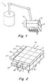
- Fig. 1 is a schematic diagram of a robot 1 manipulating a material handling tool 10 in accordance with an embodiment of the invention.
- the robot 1 moves the material handling tool 10 and allows needles 4 on the tool 10 to pick up and/or deposit material on one or more work areas, such as microtiter trays, gels containing separated DNA fragments or other biologic materials, etc.
- the robot 1 moves the tool 10 so that one or more needles 4 are appropriately positioned with respect to a microtiter tray and then actuate one or more needles 4 to remove material from, or deposit material in, wells in the microtiter tray.
- the needles may be actuated to perform other material handling operations, such as colony or plaque picking at the direction of a machine vision system.
- material handling operations such as colony or plaque picking at the direction of a machine vision system.
- the purposes and methods for such material handling are well known to those in the art and not described in detail herein.
- the robot 1 may be of any suitable type or construction and may be capable of moving the tool 10 in any suitable number of degrees of freedom.
- the robot may be a gantry-type robot capable of moving the tool 10 in three degrees of freedom.
- Other suitable robotic configurations capable of moving the tool 10 in one or more degrees of freedom may be used.
- the tool 10 and robot 1 may include a coupling to allow the robot 1 to exchange the tool 10 for other tools, thereby allowing the robot 1 to perform automated operations with different tools.
- the robot 1 or system controller may include a vision system or other suitable device to control positioning of needles 4 with respect to target areas, as is well known.
- a connection between the tool 10 and the robot 1 may provide physical support to the tool 10 as well as provide electrical power, control signals, a fluid supply or other fluid signal, etc.
- fluid refers to gases and/or liquids.
- the tool 10 includes a controller 2 that outputs signals to actuators 3 that cause corresponding needles 4 to be actuated.
- actuation of a needle 4 may cause the needle 4 to move relative to the tool 10, such as extend away from the tool to pick or place material on a work area, control flow in the needle, such as drawing fluid into or expelling fluid out from the needle, or otherwise cause the needle to perform one or more material handling functions.
- the controller 2, actuators 3 and needles 4 are all mounted to a body 5 of the tool 10.
- the body 5 has a box-like shape, the body 5 may be arranged in any suitable way.
- the needles 4 in this illustrative embodiment are arranged in a 3x4 array and extend from a bottom of the body 5, but any suitable number of needles 4 may be arranged in any suitable way on the body 5, e.g., to accommodate particular well patterns in a microtiter tray.
- the needles 4 may be arranged to receive removable pipette tips or other devices to handle materials, or may be arranged to handle materials directly.
- the controller 2 may provide any suitable signal or combination of signals to the actuators 3 to actuate the needles 4.
- the controller 2 may provide electrical signals, magnetic signals, optical signals, fluid signals (e.g., changes in fluid pressure and/or flow), or combinations of such signals, such as providing both an electrical signal and a fluid signal to the actuators 3.
- signals provided by the controller 2 will depend upon the type of actuators 3.
- the actuators 3 may be pneumatically-controlled fluid valves that open, close or otherwise change state based on a fluid signal.
- the actuators may include electrically-controlled fluid valves, relays, or other suitable devices to actuate a corresponding needle.
- the tool 10 includes one actuator for each needle, where each actuator includes a valve and associated pneumatic ram such that when the valve is open and air pressure is supplied through the open valve, the pneumatic ram may extend, and thereby extend a corresponding needle 4 from the body 5.
- the actuators may be responsive to two signals received from the controller 2 to actuate the needles 4. Having the actuators 3 respond to two signals from the controller 2 may allow for matrix-type addressing of the actuators 3, as discussed in more detail below.
- the controller 2 may operate autonomously to actuate the needles 4 or operate at the direction of a higher level controller that is part of a material handling system. For example, the controller 2 may receive a signal to activate a particular needle or group of needles at a particular time and/or position of the tool 10, and generate and output appropriate signals to cause the desired actuation. The controller 2 may receive the signals in any suitable way, such as by wired and/or wireless link, and in any suitable format and/or communications protocol.
- the controller 2 and/or higher level controller may include any suitable general purpose data processing system, which can be, or include, a suitably programmed general purpose computer, or network of general purpose computers, and other associated devices, including communication devices, and/or other circuitry or components necessary to perform the desired input/output or other functions.
- the controllers can also be implemented at least in part as single special purpose integrated circuits (e.g., ASICs), or an array of ASICs, each having a main or central processor section for overall, system-level control and separate sections dedicated to performing various different specific computations, functions and other processes under the control of the central processor section.
- the controllers can also be implemented using a plurality of separate dedicated programmable integrated or other electronic circuits or devices, e.g., hardwired electronic or logic circuits, such as discrete element circuits or programmable logic devices.
- the controllers may also include other devices, such as an information display device, user input devices, such as a keyboard, user pointing device, touch screen or other user interface, data storage devices, communication devices or other electronic circuitry or components.
- Fig. 2 shows a perspective view of a tool 10 in accordance with an embodiment of the invention.
- the tool 10 includes a 3x4 array of actuators 3 that are each associated with a corresponding needle 4.
- the controller 2 includes four control switches 21 that are associated with actuators 3 in rows across the tool 10, and drive switches 22 that are associated with actuators 3 in columns on the tool 10.
- Control signals may be provided to the control switches 21 and drive switches 22 by a portion of the controller 2 (e.g., a data processor and associated memory) on the tool 10, or by another source off of the tool 10. Based on these control signals, the control switches 21 and drive switches 22 provide suitable signals to the actuators 3 to actuate a particular needle or needles.
- the switches 21 and 22 are any suitable device capable of responding to a control signal and providing a signal to corresponding actuators 3.
- the switches 21 and 22 may include electrically-controlled valves capable of switching an associated control or drive line 23 or 24 between one or more fluid lines, e.g., sources of relatively high or low pressure, or sources of fluid flow. Pressure or other fluid flow sources may be provided to the switches 21 and 22 by lines (not shown) that lead to a pump, metering piston or other devices off of the tool body 10.
- the tool 10 is not limited to a 3x4 array, but instead may have any suitable number of actuators and/or needles arranged in any suitable pattern of rows and columns, such as a pattern that allows the needles 4 to interact with standard 96-well, 384-well or other size/configuration microtiter trays or other material sample holders.
- the 3x4 array in this illustrative embodiment is used for simplicity and ease of reference, but should in no way be interpreted as limiting aspects of the invention in any way.
- Fig. 3 shows a schematic top view of the tool 10 shown in Fig. 2 .
- Rows of actuators 3 are labelled A-D, and one control switch 21 corresponds to each row A-D.
- columns of the actuators 3 are numbered 1-3 and one drive switch 22 corresponds to each column 1-3.
- each control switch 21 provides a control signal approximately simultaneously to all actuators 3 in the corresponding row via a control line 23.
- control groups of actuators 3 in this embodiment are arranged in rows. The control signal provided to a control group causes the actuators 3 in the group to change state between an enabled state and a disabled state. In the disabled state, an actuator 3 is unable to actuate a corresponding needle 4.
- the actuator 3 In the enabled state, the actuator 3 is free to actuate the corresponding needle 4 upon receipt of an appropriate drive signal.
- Each of the drive switches 22 approximately simultaneously provides a drive signal to all actuators 3 in a corresponding column along a drive line 24.
- drive groups in this embodiment are arranged in columns.
- the drive signal causes actuators in an enabled state to actuate a corresponding needle 4.
- an actuator in a disabled state does not actuate a corresponding needle even if a drive signal that would otherwise cause actuation is received.
- individual actuators cause a corresponding needle 4 to be actuated, i.e., individual actuators 3 are addressed, by providing a control signal along the actuator's corresponding control line 23 and a drive signal along the actuator's corresponding drive line 24.
- the actuator 3 in the top right corner of the tool 10 as shown in Fig. 3 is addressed by providing a control signal from the control switch 21 for row A and providing a drive signal from the drive switch 22 for column 3.
- Other actuators in the row A and in column 3 will not actuate a corresponding needle 4, unless an appropriate control signal and drive signal are received along appropriate lines.
- actuators in the row A and in columns 1 and 2 will not be actuated unless drive signals are provided by the drive switches 22 for columns 1 and 2.
- individual needles 4 may be actuated by providing appropriate signals to groups, e.g., rows and/or columns, of actuators in the tool 10.
- selected groups of actuators 3 may be addressed by providing appropriate signals along the rows A-D and columns 1-3.
- all needles on the tool 10, or selected needles, in a particular row or column may be approximately simultaneously actuated, e.g., all of the actuators 3 in row A may be actuated by providing an appropriate control signal from the control switch 21 for row A and appropriate drive signals from the drive switches 22 for columns 1-3.
- other selected groups of needles may be approximately simultaneously actuated by providing signals on appropriate control and drive lines 23 and 24.
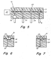
- Fig. 4 shows a cross-sectional view of the tool 10 along the line A-A in Fig. 3
- Fig. 5 shows a cross-sectional view of the tool 10 along the line B-B in Fig. 3
- the actuators 3 may take any suitable form, but in this illustrative embodiment, include one or more membrane valves 31.
- the various control lines 23, drive lines 24, needle channels 33, chambers for valves 31 and other features are formed in upper and lower blocks 11 and 12 of the tool body 10.
- the blocks 11 and 12 may be made of any suitable material(s), such as plastic, and the channels, lines, chambers and other features may be formed in any suitable way using any suitable process.
- each block may be made of multiple layers of plastic material that have grooves, channels or are otherwise formed to create the desired lines, channels, etc. in the tool body 10. These layers may be joined together, e.g., by heating the layers and pressing them together, to form a unitary block.
- the membrane valves 31 may be formed by positioning a flexible member 6, such as a sheet of silicone rubber, between the blocks 11 and 12 and securing the blocks 11 and 12 together. The construction of membrane valves is well known, and alternate methods of construction will be appreciated by those of skill in the art.
- the membrane valves 31 operate based on a control signal provided along a corresponding control line 23.
- a control signal provided along a corresponding control line 23.
- the control switch 21 may include a valve or other arrangement that selectively switches the control line 23 between a source of high pressure and ambient or relatively lower pressure to control the valves 31 along the control line 23.
- Figures 4 and 5 show that rows of valves 31 are connected to a common control line 23, and columns of valves 31 are connected to a common drive line 24.
- Signals provided on the control lines 23 in this embodiment serve to switch the valves 31 between an open (or enabled) state and closed (or disabled) state.
- a drive signal provided along the valve's drive line 24 may be provided through the valve 31 to an associated needle channel 33. Therefore, a control signal is provided to valves 31 in a row to switch the valves to an enabled state, and a drive signal supplied to a drive line 24 for the valves 31 in an enabled state may cause actuation of needles corresponding to the enabled valves 31.
- actuators 3 in a tool 10 may include a membrane valve or other similar device to control fluid flow in a needle 4, or may include a membrane valve and pneumatic ram to control movement of an associated needle 4.
- the control and drive signals may also cause the membrane valves 31 to perform other actuation operations with respect to the needles, such as pumping fluid through a corresponding needle channel 33 and/or drawing or expelling a metered amount of fluid into or out of a corresponding needle 4.
- Pumping and metering operations may be performed by, for example, moving the flexible member in a valve 31 to a closed state, closing a drive line 24 for the valve 31 at a drive switch 22, and moving the flexible member in the valve 31 to an open state, thereby causing fluid to be drawn into the needle 4.
- Movement of the flexible member 6 may be closely controlled to perform accurate fluid metering through the valve's needle, e.g., by controlling the amount of fluid drawn from the valve by the control line 23.
- Such control can be performed by a metering piston coupled to the control line 23 or drive line 24, by accurately timing the opening and closing of a valve in the control switch 21 while supplying a constant fluid flow through the valve 31, or other means as will be appreciated by those of skill in the art.
- control and drive switches in this illustrative embodiment control fluid flow to corresponding rows and columns of valves
- the switches may provide other signal types to the actuators, such as electrical, optical, magnetic and other signal types.
- the actuators and/or valves 31 in this embodiment may include other suitable element(s), such as electrical or optical relays, transistors, optical valves, etc.
- the actuators 3 may include other drive elements, such as hydraulic rams, solenoid actuators, motors, and so on. Therefore, any suitable arrangement of elements may be used as actuators to receive control and drive signals and actuate a corresponding needle.
Landscapes
- Analytical Chemistry (AREA)
- Immunology (AREA)
- Physics & Mathematics (AREA)
- Health & Medical Sciences (AREA)
- Life Sciences & Earth Sciences (AREA)
- Chemical & Material Sciences (AREA)
- General Health & Medical Sciences (AREA)
- Biochemistry (AREA)
- Pathology (AREA)
- General Physics & Mathematics (AREA)
- Engineering & Computer Science (AREA)
- Robotics (AREA)
- Apparatus Associated With Microorganisms And Enzymes (AREA)
- Automatic Analysis And Handling Materials Therefor (AREA)
Claims (15)
- Robotisch manipulierbares Materialhandhabungswerkzeug (10), umfassend:einen Werkzeugkörper (5);mehrere Nadeln (4), die an dem Werkzeugkörper in M Spalten und N Reihen montiert sind, wobei jede der mehreren Nadeln dazu ausgestaltet und angeordnet ist, Material von einem Arbeitsgebiet zu entfernen und an einem Arbeitsgebiet zu deponieren; undmehrere Aktoren (3, 31), wobei jeder der mehreren Aktoren mit einer korrespondierenden der mehreren Nadeln verbunden ist und dazu ausgestaltet und angeordnet ist, die korrespondierende Nadel zu betätigen,gekennzeichnet durch:die mehrere Aktoren, die in einer ersten Anzahl von Steuerungsgruppen gruppiert sind, wobei Aktoren in jeder Steuerungsgruppe verbunden sind, sodass ein gemeinsames Steuerungssignal gleichzeitig für alle Aktoren in der korrespondierenden Steuerungsgruppe bereitgestellt werden kann, und eine zweite Anzahl von Antriebsgruppen gruppiert sind, wobei Aktoren in jeder Antriebsgruppe verbunden sind, sodass ein gemeinsames Antriebssignal gleichzeitig für alle Aktoren in der korrespondierenden Antriebsgruppe bereitgestellt werden kann, wobei das gemeinsame Steuerungssignal die Aktoren in der korrespondierenden Steuerungsgruppe dazu bringt, zwischen einem aktiven oder einem inaktiven Zustand zu wechseln, wobei ein Aktor in einem aktiven Zustand dazu in der Lage ist, eine korrespondierende Nadel zu betätigen, und ein Aktor in einem inaktiven Zustand nicht dazu in der Lage ist, eine korrespondierende Nadel zu betätigen, wobei das gemeinsame Antriebssignal eine Betätigung einer Nadel verursacht, wenn es von einem Aktor in einem aktiven Zustand empfangen wird;jede Steuerungsgruppe von Aktoren ist mit einer korrespondierenden der N Reihen von Nadeln angeordnet und jede Antriebsgruppe von Aktoren ist mit einer korrespondierenden der M Spalten von Nadeln angeordnet, wobei jede Steuerungsgruppe und jede Antriebsgruppe zwei oder mehr Aktoren aufweist und jede Steuerungsgruppe und jede Antriebsgruppe nur einen Aktor gemeinsam aufweist;mehrere Steuerungsschalter (21), die an dem Werkzeugkörper montiert sind, wobei jeder der mehreren Steuerungsschalter mit einer korrespondierenden Steuerungsgruppe von allen Aktoren in einer der N Reihen verbunden ist, und jeder der mehreren Steuerungsschalter dazu ausgestaltet ist, ein Steuerungssignal gleichzeitig für alle Aktoren in der korrespondierenden Steuerungsgruppe von Aktoren bereitzustellen; undmehrere Antriebsschalter (22), die an dem Werkzeugkörper montiert sind, wobei jeder der mehreren Antriebsschalter mit einer korrespondierenden Antriebsgruppe von allen Aktoren in einer der M Spalten verbunden ist, und jeder der mehreren Antriebsschalter dazu ausgestaltet ist, ein Antriebssignal gleichzeitig zu allen Aktoren in der korrespondierenden Antriebsgruppe von Aktoren bereitzustellen,wobei die mehreren Steuerungsschalter dazu ausgestaltet und angeordnet sind, Steuerungssignale und Antriebssignale bereitzustellen, um jeweils einzeln jede der mehreren Nadeln zu betätigen, wobei die absolute Anzahl von Steuerungssignalen und Antriebssignalen kleiner als die Anzahl von Nadeln ist und eine Steuerung (2) vorgesehen ist, die dazu ausgestaltet ist, die Aktoren zu steuern, um jede Nadel einzeln zu betätigen.
- Werkzeug nach Anspruch 1, wobei mindestens einer der Aktoren ein Membranventil ist, das dazu ausgestaltet ist, Fluidfluss für eine Nadel zu steuern.
- Werkzeug nach Anspruch 1 oder 2, wobei die mehreren Steuerungsschalter N Ventile beinhalten, die jeweils angeordnet sind, um ein Luftdrucksignal für die Aktoren in einer korrespondierenden Steuerungsgruppe bereitzustellen.
- Werkzeug nach einem der Ansprüche 1 bis 3, wobei die mehreren Antriebsschalter M Ventile beinhalten, die jeweils angeordnet sind, um einen Fluidfluss zu Aktoren in einer korrespondierenden Steuerungsgruppe bereitzustellen.
- Werkzeug nach einem der Ansprüche 1 bis 4, wobei die absolute Anzahl von Steuerungssignalen und Antriebssignalen, die durch die Steuerungsschalter und die Antriebsschalter bereitgestellt werden, gleich M + N ist.
- Werkzeug nach einem der Ansprüche 1 bis 5, wobei die Steuerungssignale und Antriebssignale jeweils Fluidsteuerungssignale und Fluidantriebssignale sind.
- Werkzeug nach einem der Ansprüche 1 bis 6, wobei die Steuerung dazu ausgestaltet ist gleichzeitig gewählte Gruppen von Nadeln zu betätigen.
- Werkzeug nach einem der Ansprüche 1 bis 7, wobei ein Betätigen einer Nadel ein Einziehen von Flüssigkeit in oder Ausstoßen von Flüssigkeit aus einer Nadel beinhaltet.
- Werkzeug nach einem der Ansprüche 1 bis 8, wobei ein Betätigen einer Nadel ein Ausfahren der Nadel von dem Werkzeugkörper beinhaltet.
- Werkzeug nach einem der Ansprüche 1 bis 9 ferner jeweilige Steuerungsleitungen (23) umfassend, mit denen das Steuerungssignal von jedem der Steuerungsschalter für eine entsprechende Steuerungsgruppe bereitgestellt wird.
- Werkzeug nach einem der Ansprüche 1 bis 10, ferner jeweilige Antriebsleitungen (24) umfassend, mit denen das Antriebssignal von jedem der Antriebsschalter für eine entsprechende Antriebsgruppe bereitgestellt wird.
- Verfahren zum Steuern eines robotisch manipulierbaren Materialhandhabungswerkzeugs (10), umfassend:Bereitstellen eines Werkzeugkörpers (5), der eine erste Anzahl von Nadeln (4) aufweist, die an dem Werkzeugkörper in M Spalten und N Reihen montiert sind, wobei jede der mehreren Nadeln dazu ausgestaltet und angeordnet ist, Material von einem Arbeitsgebiet zu entfernen und an einem Arbeitsgebiet zu deponieren;Bereitstellen von mehreren Aktoren (3, 31), wobei jeder der mehreren Aktoren mit einer korrespondierenden ersten Anzahl Nadeln verbunden ist, um die korrespondierende Nadel zu betätigen, wobei die mehrere Aktoren in einer ersten Anzahl von Steuerungsgruppen gruppiert sind, wobei Aktoren in jeder Steuerungsgruppe verbunden sind, sodass ein gemeinsames Steuerungssignal gleichzeitig für alle Aktoren in der korrespondierenden Steuerungsgruppe bereitgestellt werden kann, und einer zweite Anzahl von Antriebsgruppen gruppiert sind, wobei Aktoren in jeder Antriebsgruppe verbunden sind, sodass ein gemeinsames Antriebssignal gleichzeitig für alle Aktoren in der korrespondierenden Antriebsgruppe bereitgestellt werden kann, wobei das gemeinsame Steuerungssignal die Aktoren in der korrespondierenden Steuerungsgruppe dazu bringt, zwischen einem aktiven oder einem inaktiven Zustand zu wechseln, wobei ein Aktor in einem aktiven Zustand dazu in der Lage ist, eine korrespondierende Nadel zu betätigen, und ein Aktor in einem inaktiven Zustand nicht dazu in der Lage ist, eine korrespondierende Nadel zu betätigen, wobei das gemeinsame Antriebssignal eine Betätigung einer Nadel verursacht, wenn es von einem Aktor in einem aktiven Zustand empfangen wird;jede Steuerungsgruppe von Aktoren ist mit einer korrespondierenden der N Reihen von Nadeln angeordnet und jede Antriebsgruppe von Aktoren ist mit einer korrespondierenden der M Spalten von Nadeln angeordnet, wobei jede Steuerungsgruppe und jede Antriebsgruppe zwei oder mehr Aktoren aufweisen und jede Steuerungsgruppe und jede Antriebsgruppe nur einen Aktor gemeinsam aufweisen;Bereitstellen von mehreren Steuerungsschaltern (21), die an dem Werkzeugkörper montiert sind, wobei jeder der mehreren Steuerungsschalter mit einer korrespondierenden Steuerungsgruppe von allen Aktoren in einer der N Reihen verbunden ist, und jeder der mehreren Steuerungsschalter ein Steuerungssignal gleichzeitig für alle Aktoren in der korrespondierenden Steuerungsgruppe von Aktoren bereitstellt;Bereitstellen von mehreren Antriebsschaltern (22), die an dem Werkzeugkörper montiert sind, wobei jeder der mehreren Antriebsschalter mit einer korrespondierenden Antriebsgruppe von allen Aktoren in einer der M Spalten verbunden ist, und jeder der mehreren Antriebsschalter ein Antriebssignal gleichzeitig für allen Aktoren in der korrespondierenden Antriebsgruppe von Aktoren bereitzustellt; undBereitstellen einer Steuerung, die ausgestaltet und angeordnet ist, jeden der Aktoren zu steuern, indem diese ein Maximum einer zweiten Anzahl von Signalen für die Aktoren bereitstellt, wobei die zweite Anzahl von Signalen kleiner als die erste Anzahl von Nadeln ist, wobei die Steuerung dazu ausgestaltet ist, die Aktoren zu steuern, um jede Nadel einzeln zu betätigen.
- Verfahren nach Anspruch 12, wobei die Steuerung dazu ausgestaltet ist, gleichzeitig ausgewählte Gruppen von Nadeln zu steuern.
- Verfahren nach Anspruch 12 oder 13, ferner ein Bereitstellen von jeweiligen Steuerungsleitungen (23) umfassend, mit denen das Steuerungssignal von jedem der Steuerungsschalter für eine entsprechende Steuerungsgruppe bereitgestellt wird.
- Verfahren nach einem der Ansprüche 12 bis 14, ferner ein Bereitstellen von jeweilige Antriebsleitungen (24) umfassend, mit denen das Antriebssignal von jedem der Antriebsschalter für eine entsprechende Antriebsgruppe bereitgestellt wird.
Applications Claiming Priority (3)
| Application Number | Priority Date | Filing Date | Title |
|---|---|---|---|
| US113865 | 1998-07-10 | ||
| US10/113,865 US6637476B2 (en) | 2002-04-01 | 2002-04-01 | Robotically manipulable sample handling tool |
| PCT/US2003/009470 WO2003085407A1 (en) | 2002-04-01 | 2003-03-28 | Robotically manipulable sample handling tool |
Publications (2)
| Publication Number | Publication Date |
|---|---|
| EP1493036A1 EP1493036A1 (de) | 2005-01-05 |
| EP1493036B1 true EP1493036B1 (de) | 2015-12-09 |
Family
ID=28453694
Family Applications (1)
| Application Number | Title | Priority Date | Filing Date |
|---|---|---|---|
| EP03718082.5A Expired - Lifetime EP1493036B1 (de) | 2002-04-01 | 2003-03-28 | Robotisch manipulierbares proben-verarbeitungswerkzeug |
Country Status (5)
| Country | Link |
|---|---|
| US (1) | US6637476B2 (de) |
| EP (1) | EP1493036B1 (de) |
| JP (1) | JP4286152B2 (de) |
| AU (1) | AU2003222096A1 (de) |
| WO (1) | WO2003085407A1 (de) |
Families Citing this family (23)
| Publication number | Priority date | Publication date | Assignee | Title |
|---|---|---|---|---|
| JP2003149255A (ja) * | 2001-11-15 | 2003-05-21 | Toyobo Co Ltd | 直交座標および円筒座標に移動可能な分注装置 |
| JP2003241208A (ja) * | 2002-02-19 | 2003-08-27 | Shibaura Mechatronics Corp | 液晶滴下装置及び方法並びに液晶表示パネル製造装置 |
| US7452712B2 (en) | 2002-07-30 | 2008-11-18 | Applied Biosystems Inc. | Sample block apparatus and method of maintaining a microcard on a sample block |
| US7249529B2 (en) * | 2003-03-28 | 2007-07-31 | Protedyne Corporation | Robotically manipulable sample handling tool |
| AU2004245123A1 (en) * | 2003-06-05 | 2004-12-16 | Bioprocessors Corp. | System and method for process automation |
| US20050221358A1 (en) * | 2003-09-19 | 2005-10-06 | Carrillo Albert L | Pressure chamber clamp mechanism |
| US20070015289A1 (en) * | 2003-09-19 | 2007-01-18 | Kao H P | Dispenser array spotting |
| US20050233472A1 (en) * | 2003-09-19 | 2005-10-20 | Kao H P | Spotting high density plate using a banded format |
| US20050226779A1 (en) * | 2003-09-19 | 2005-10-13 | Oldham Mark F | Vacuum assist for a microplate |
| DE10345338B4 (de) * | 2003-09-21 | 2015-08-06 | Inova Pharma Systems Gmbh | Verfahren und Vorrichtung zum kontrollierten Befüllen |
| US7270789B1 (en) * | 2004-03-15 | 2007-09-18 | Astle Thomas W | Pipettor head having standpipes open at their tops to a pressure/vacuum chamber and method |
| US7201072B1 (en) | 2004-08-26 | 2007-04-10 | Elemental Scientific Inc. | Automated sampling device |
| US7637175B1 (en) | 2004-08-26 | 2009-12-29 | Elemental Scientific, Inc. | Automated sampling device |
| US7690275B1 (en) | 2004-08-26 | 2010-04-06 | Elemental Scientific, Inc. | Automated sampling device |
| US7534081B2 (en) | 2005-05-24 | 2009-05-19 | Festo Corporation | Apparatus and method for transferring samples from a source to a target |
| US7597520B2 (en) | 2005-05-24 | 2009-10-06 | Festo Corporation | Apparatus and method for transferring samples from a source to a target |
| US20070095413A1 (en) * | 2005-11-01 | 2007-05-03 | Georgia Tech Research Corporation | Systems and methods for controlling the flow of a fluidic medium |
| US9103806B2 (en) * | 2006-04-24 | 2015-08-11 | Protedyne Corporation | Robotic system with autonomously operable tools |
| US7799281B2 (en) | 2007-01-16 | 2010-09-21 | Festo Corporation | Flux concentrator for biomagnetic particle transfer device |
| US9341229B1 (en) | 2012-09-10 | 2016-05-17 | Elemental Scientific, Inc. | Automated sampling device |
| CA2987419C (en) * | 2015-05-28 | 2023-08-01 | Bd Kiestra B.V. | Automated method and system for obtaining and preparing microorganism sample for both identification and antibiotic susceptibility tests |
| DE102016118183B3 (de) * | 2016-09-27 | 2017-11-16 | Sartorius Lab Instruments Gmbh & Co. Kg | Verteilerkopf für eine Saugpumpe |
| WO2018226876A1 (en) | 2017-06-06 | 2018-12-13 | The Regents Of The University Of California | Systems and methods for rapid generation of droplet libraries |
Family Cites Families (73)
| Publication number | Priority date | Publication date | Assignee | Title |
|---|---|---|---|---|
| US3568735A (en) * | 1968-06-26 | 1971-03-09 | Cooke Eng Co | Laboratory microtitration dispensing apparatus |
| US3782682A (en) | 1971-11-01 | 1974-01-01 | W Lale | Fluid flow controller |
| US3744376A (en) | 1972-03-16 | 1973-07-10 | Synalloy Corp | Pressure fluid control arrangement and method |
| FR2194896B1 (de) | 1972-08-04 | 1976-01-23 | Gachot Jean Fr | |
| US3881846A (en) | 1973-08-06 | 1975-05-06 | Outboard Marine Corp | Fluid pump with resilient pumping membrane |
| US4148334A (en) | 1975-09-05 | 1979-04-10 | Fluid Device Corporation | Liquid level control sytem |
| US4119120A (en) | 1976-11-29 | 1978-10-10 | Beckman Instruments, Inc. | Fluid switch |
| DE2821801C3 (de) | 1978-05-19 | 1981-06-25 | Friedrich Wilhelm 6535 Gau-Algesheim Schmitt | Ventilanordnung mit Membranventilen |
| US4262711A (en) | 1979-02-13 | 1981-04-21 | Anderson Joseph A | Microplate filler |
| US4283008A (en) | 1979-06-04 | 1981-08-11 | The Trane Company | Pressurized signal control apparatus |
| US4304257A (en) | 1980-07-01 | 1981-12-08 | Instrumentation Laboratory Inc. | Valve with flexible sheet member |
| US4451023A (en) | 1981-09-08 | 1984-05-29 | Mil Mutzarim Techniim (1971) B.M. | Tube-diaphragm valve |
| US4459864A (en) * | 1981-10-19 | 1984-07-17 | Electro-Nucleonics, Inc. | Fluid loading and dispensing device |
| US4824072A (en) | 1983-11-08 | 1989-04-25 | Mil Mutzarim Techniim (1971) B.M. | Tube-diaphragm valve |
| US4532805A (en) | 1984-05-29 | 1985-08-06 | Flesher Robert W | Pipette system |
| EP0253064A3 (de) | 1986-07-08 | 1988-10-26 | AVS Ing. J.C. Römer GmbH | Membranventil für Fluide |
| US4844872A (en) | 1987-07-17 | 1989-07-04 | Fisher Scientific Company | Fluid handling |
| US4906432B1 (en) | 1987-07-17 | 1991-06-25 | Liquid handling | |
| US4771204A (en) | 1987-07-30 | 1988-09-13 | Kiwi Coders Corporation | Sealing method and means for fluid control device |
| US4848722A (en) | 1987-12-11 | 1989-07-18 | Integrated Fluidics, Inc. | Valve with flexible sheet member |
| US4858883A (en) | 1987-12-11 | 1989-08-22 | Integrated Fluidics, Inc. | Valve with flexible sheet member |
| US4852851A (en) | 1987-12-11 | 1989-08-01 | Integrated Fluidics, Inc. | Valve with flexible sheet member |
| DE3837366A1 (de) | 1988-11-03 | 1990-05-10 | Hartwig Straub | Membranventil mit einer von einem ventildeckel abgestuetzten elastischen membrane |
| US5154693A (en) | 1990-05-15 | 1992-10-13 | Pudenz-Schulte Medical Research Corp. | Flow control device having selectable alternative fluid pathways |
| ATE119241T1 (de) | 1990-07-10 | 1995-03-15 | Westonbridge Int Ltd | Ventil, methode zur herstellung dises ventils und mit diesem ventil versehene mikropumpe. |
| US5197192A (en) | 1990-08-01 | 1993-03-30 | Photovac Incorporated | Method of making a fluid control valve |
| US5083742A (en) | 1990-08-01 | 1992-01-28 | Photovac Incorporated | Fluid control valve |
| US5176359A (en) | 1991-05-20 | 1993-01-05 | Photovac International, Inc. | Fluid control valve arrangement |
| JPH0510958A (ja) * | 1991-07-02 | 1993-01-19 | Olympus Optical Co Ltd | 分析装置 |
| US5226462A (en) * | 1991-07-26 | 1993-07-13 | Carl Richard A | Introducing measured amounts of liquid into receptacles |
| US5203368A (en) | 1992-07-29 | 1993-04-20 | Protein Technologies Inc. | Matrix of valves |
| US5343909A (en) | 1992-12-17 | 1994-09-06 | Jack Goodman | Liquid transfer device |
| WO1995009987A1 (en) | 1993-10-04 | 1995-04-13 | Research International, Inc. | Micromachined fluid flow regulators |
| ATE170001T1 (de) | 1993-10-21 | 1998-09-15 | Abbott Lab | Vorrichtung und verfahren zur überführung einer probe eines fluids |
| US5496009A (en) | 1994-10-07 | 1996-03-05 | Bayer Corporation | Valve |
| US5834314A (en) | 1994-11-07 | 1998-11-10 | Abbott Laboratories | Method and apparatus for metering a fluid |
| AU715130B2 (en) | 1994-11-17 | 2000-01-20 | Yoshino Kogyosho Co., Ltd. | Container with pump for discharging bubbles |
| FR2727736B1 (fr) | 1994-12-02 | 1997-01-24 | Eaton Sa Monaco | Vanne commandee par un fluide |
| JP3481705B2 (ja) * | 1994-12-12 | 2003-12-22 | 株式会社モリテックス | 自動固相抽出装置 |
| US5775371A (en) | 1995-03-08 | 1998-07-07 | Abbott Laboratories | Valve control |
| EP0839343B1 (de) | 1995-07-20 | 2001-10-17 | Abbott Laboratories | Ventilkonstruktion und -verwendung |
| CA2249978C (en) | 1996-01-26 | 2002-03-12 | Autotrol Corporation | Adaptable control valve for fluid treatment system |
| US5967163A (en) | 1996-01-30 | 1999-10-19 | Abbott Laboratories | Actuator and method |
| US5660370A (en) | 1996-03-07 | 1997-08-26 | Integrated Fludics, Inc. | Valve with flexible sheet member and two port non-flexing backer member |
| GB9615109D0 (en) | 1996-07-18 | 1996-09-04 | Evans Rowland F | Diaphragm valve,unit,assembly and system |
| US5941501A (en) | 1996-09-06 | 1999-08-24 | Xerox Corporation | Passively addressable cantilever valves |
| US6123316A (en) | 1996-11-27 | 2000-09-26 | Xerox Corporation | Conduit system for a valve array |
| US5971355A (en) | 1996-11-27 | 1999-10-26 | Xerox Corporation | Microdevice valve structures to fluid control |
| US5865224A (en) * | 1996-12-20 | 1999-02-02 | Life Technologies, Inc. | Method and apparatus for automated dispensing |
| FR2759760B1 (fr) | 1997-02-17 | 1999-05-21 | Asm France Sa | Vanne a membrane |
| DE19802367C1 (de) * | 1997-02-19 | 1999-09-23 | Hahn Schickard Ges | Mikrodosiervorrichtungsarray und Verfahren zum Betreiben desselben |
| US6074611A (en) | 1997-04-28 | 2000-06-13 | Apogee Designs, Ltd. | Micro-pipettor apparatus |
| US6012902A (en) | 1997-09-25 | 2000-01-11 | Caliper Technologies Corp. | Micropump |
| US5836750A (en) | 1997-10-09 | 1998-11-17 | Honeywell Inc. | Electrostatically actuated mesopump having a plurality of elementary cells |
| US6106245A (en) | 1997-10-09 | 2000-08-22 | Honeywell | Low cost, high pumping rate electrostatically actuated mesopump |
| KR100279552B1 (ko) | 1997-10-18 | 2001-11-30 | 박한오 | 다중단속밸브장치 |
| US6007046A (en) | 1997-12-15 | 1999-12-28 | Coulter International Corp. | Fluid transport circuit and valve structure therefor |
| US6089534A (en) | 1998-01-08 | 2000-07-18 | Xerox Corporation | Fast variable flow microelectromechanical valves |
| US6033911A (en) * | 1998-02-27 | 2000-03-07 | Hamilton Company | Automated assaying device |
| US5976470A (en) * | 1998-05-29 | 1999-11-02 | Ontogen Corporation | Sample wash station assembly |
| DE19835833A1 (de) | 1998-08-07 | 2000-02-17 | Max Planck Gesellschaft | Dosierkopf zur parallelen Bearbeitung einer Vielzahl von Fluidproben |
| US6039211A (en) * | 1998-09-22 | 2000-03-21 | Glaxo Wellcome Inc. | Position triggered dispenser and methods |
| US6158712A (en) | 1998-10-16 | 2000-12-12 | Agilent Technologies, Inc. | Multilayer integrated assembly having an integral microminiature valve |
| DE69836836T2 (de) | 1998-11-06 | 2007-06-28 | Honeywell, Inc., Minneapolis | Elektrostatisch betätigte pumpenarray |
| US6143252A (en) * | 1999-04-12 | 2000-11-07 | The Perkin-Elmer Corporation | Pipetting device with pipette tip for solid phase reactions |
| EP1194693B1 (de) | 1999-06-28 | 2006-10-25 | California Institute Of Technology | Mikromechanische pump- und ventilsysteme |
| US6176399B1 (en) | 1999-07-12 | 2001-01-23 | Aptargroup, Inc | Valved dispensing system for multiple dispensing streams |
| US6244119B1 (en) | 1999-08-03 | 2001-06-12 | Wallac Oy | Multichannel pipette system and pipette tips therefor |
| US6240944B1 (en) | 1999-09-23 | 2001-06-05 | Honeywell International Inc. | Addressable valve arrays for proportional pressure or flow control |
| US6257268B1 (en) | 1999-12-01 | 2001-07-10 | Gilmore Valve Company | Pressure biased shuttle valve |
| US7160511B2 (en) | 2000-02-18 | 2007-01-09 | Olympus Corporation | Liquid pipetting apparatus and micro array manufacturing apparatus |
| ES2178915B1 (es) | 2000-03-07 | 2004-04-16 | Plasticos Mondragon, S.A. | Valvula hidraulica de membrana perfeccionada, para regulacion del caudal de fluidos. |
| WO2002018053A1 (en) * | 2000-08-30 | 2002-03-07 | Cartesian Technologies, Inc. | Method and apparatus for high-speed microfluidic dispensing using text file control |
-
2002
- 2002-04-01 US US10/113,865 patent/US6637476B2/en not_active Expired - Lifetime
-
2003
- 2003-03-28 WO PCT/US2003/009470 patent/WO2003085407A1/en not_active Ceased
- 2003-03-28 AU AU2003222096A patent/AU2003222096A1/en not_active Abandoned
- 2003-03-28 JP JP2003582543A patent/JP4286152B2/ja not_active Expired - Fee Related
- 2003-03-28 EP EP03718082.5A patent/EP1493036B1/de not_active Expired - Lifetime
Also Published As
| Publication number | Publication date |
|---|---|
| JP4286152B2 (ja) | 2009-06-24 |
| EP1493036A1 (de) | 2005-01-05 |
| US6637476B2 (en) | 2003-10-28 |
| US20030183301A1 (en) | 2003-10-02 |
| WO2003085407A1 (en) | 2003-10-16 |
| AU2003222096A1 (en) | 2003-10-20 |
| JP2005521889A (ja) | 2005-07-21 |
Similar Documents
| Publication | Publication Date | Title |
|---|---|---|
| EP1493036B1 (de) | Robotisch manipulierbares proben-verarbeitungswerkzeug | |
| US7438857B2 (en) | Liquid handling tool having porous plunger | |
| US7125727B2 (en) | Sample handling tool with piezoelectric actuator | |
| US6506611B2 (en) | Metering head for parallel processing of a plurality of fluid samples | |
| US20020119077A1 (en) | Liquid chemical distribution method and apparatus | |
| US7135146B2 (en) | Universal non-contact dispense peripheral apparatus and method for a primary liquid handling device | |
| US7249529B2 (en) | Robotically manipulable sample handling tool | |
| US20080240898A1 (en) | Laboratory Robot Assembly | |
| EP1542837A1 (de) | Mit einem roboter handhabbares werkzeug mit bordprozessor | |
| CA2348056A1 (en) | Position triggered dispenser and methods | |
| EP4609206A1 (de) | Laborautomatisierungsvorrichtungen sowie entsprechende systeme und verfahren | |
| WO2004076018A2 (en) | Reagent dispenser and dispensing method | |
| EP1663494B1 (de) | Verfahren und vorrichtung zur handhabung von kleinvolumigen fluidproben | |
| US7009133B2 (en) | Wire-cut electric discharge machine | |
| CN220590096U (zh) | 一种适用于实验室的自动化平台及桌面型自动化装置 | |
| CA2459730C (en) | Secondary liquid dispensing module for liquid handling system | |
| WO2003023410A1 (en) | Secondary liquid dispensing module for liquid handling system |
Legal Events
| Date | Code | Title | Description |
|---|---|---|---|
| PUAI | Public reference made under article 153(3) epc to a published international application that has entered the european phase |
Free format text: ORIGINAL CODE: 0009012 |
|
| 17P | Request for examination filed |
Effective date: 20041102 |
|
| AK | Designated contracting states |
Kind code of ref document: A1 Designated state(s): AT BE BG CH CY CZ DE DK EE ES FI FR GB GR HU IE IT LI LU MC NL PT RO SE SI SK TR |
|
| AX | Request for extension of the european patent |
Extension state: AL LT LV MK |
|
| 17Q | First examination report despatched |
Effective date: 20101221 |
|
| GRAP | Despatch of communication of intention to grant a patent |
Free format text: ORIGINAL CODE: EPIDOSNIGR1 |
|
| INTG | Intention to grant announced |
Effective date: 20150608 |
|
| GRAS | Grant fee paid |
Free format text: ORIGINAL CODE: EPIDOSNIGR3 |
|
| GRAA | (expected) grant |
Free format text: ORIGINAL CODE: 0009210 |
|
| AK | Designated contracting states |
Kind code of ref document: B1 Designated state(s): AT BE BG CH CY CZ DE DK EE ES FI FR GB GR HU IE IT LI LU MC NL PT RO SE SI SK TR |
|
| REG | Reference to a national code |
Ref country code: GB Ref legal event code: FG4D |
|
| REG | Reference to a national code |
Ref country code: AT Ref legal event code: REF Ref document number: 764814 Country of ref document: AT Kind code of ref document: T Effective date: 20151215 Ref country code: CH Ref legal event code: EP |
|
| REG | Reference to a national code |
Ref country code: IE Ref legal event code: FG4D |
|
| REG | Reference to a national code |
Ref country code: DE Ref legal event code: R096 Ref document number: 60348322 Country of ref document: DE |
|
| REG | Reference to a national code |
Ref country code: NL Ref legal event code: MP Effective date: 20151209 |
|
| PG25 | Lapsed in a contracting state [announced via postgrant information from national office to epo] |
Ref country code: ES Free format text: LAPSE BECAUSE OF FAILURE TO SUBMIT A TRANSLATION OF THE DESCRIPTION OR TO PAY THE FEE WITHIN THE PRESCRIBED TIME-LIMIT Effective date: 20151209 |
|
| PGFP | Annual fee paid to national office [announced via postgrant information from national office to epo] |
Ref country code: DE Payment date: 20160322 Year of fee payment: 14 |
|
| REG | Reference to a national code |
Ref country code: AT Ref legal event code: MK05 Ref document number: 764814 Country of ref document: AT Kind code of ref document: T Effective date: 20151209 |
|
| PG25 | Lapsed in a contracting state [announced via postgrant information from national office to epo] |
Ref country code: SE Free format text: LAPSE BECAUSE OF FAILURE TO SUBMIT A TRANSLATION OF THE DESCRIPTION OR TO PAY THE FEE WITHIN THE PRESCRIBED TIME-LIMIT Effective date: 20151209 Ref country code: GR Free format text: LAPSE BECAUSE OF FAILURE TO SUBMIT A TRANSLATION OF THE DESCRIPTION OR TO PAY THE FEE WITHIN THE PRESCRIBED TIME-LIMIT Effective date: 20160310 Ref country code: NL Free format text: LAPSE BECAUSE OF FAILURE TO SUBMIT A TRANSLATION OF THE DESCRIPTION OR TO PAY THE FEE WITHIN THE PRESCRIBED TIME-LIMIT Effective date: 20151209 Ref country code: FI Free format text: LAPSE BECAUSE OF FAILURE TO SUBMIT A TRANSLATION OF THE DESCRIPTION OR TO PAY THE FEE WITHIN THE PRESCRIBED TIME-LIMIT Effective date: 20151209 |
|
| PGFP | Annual fee paid to national office [announced via postgrant information from national office to epo] |
Ref country code: GB Payment date: 20160323 Year of fee payment: 14 |
|
| PG25 | Lapsed in a contracting state [announced via postgrant information from national office to epo] |
Ref country code: CZ Free format text: LAPSE BECAUSE OF FAILURE TO SUBMIT A TRANSLATION OF THE DESCRIPTION OR TO PAY THE FEE WITHIN THE PRESCRIBED TIME-LIMIT Effective date: 20151209 Ref country code: IT Free format text: LAPSE BECAUSE OF FAILURE TO SUBMIT A TRANSLATION OF THE DESCRIPTION OR TO PAY THE FEE WITHIN THE PRESCRIBED TIME-LIMIT Effective date: 20151209 |
|
| PG25 | Lapsed in a contracting state [announced via postgrant information from national office to epo] |
Ref country code: AT Free format text: LAPSE BECAUSE OF FAILURE TO SUBMIT A TRANSLATION OF THE DESCRIPTION OR TO PAY THE FEE WITHIN THE PRESCRIBED TIME-LIMIT Effective date: 20151209 Ref country code: EE Free format text: LAPSE BECAUSE OF FAILURE TO SUBMIT A TRANSLATION OF THE DESCRIPTION OR TO PAY THE FEE WITHIN THE PRESCRIBED TIME-LIMIT Effective date: 20151209 Ref country code: BE Free format text: LAPSE BECAUSE OF NON-PAYMENT OF DUE FEES Effective date: 20160331 Ref country code: RO Free format text: LAPSE BECAUSE OF FAILURE TO SUBMIT A TRANSLATION OF THE DESCRIPTION OR TO PAY THE FEE WITHIN THE PRESCRIBED TIME-LIMIT Effective date: 20151209 Ref country code: SK Free format text: LAPSE BECAUSE OF FAILURE TO SUBMIT A TRANSLATION OF THE DESCRIPTION OR TO PAY THE FEE WITHIN THE PRESCRIBED TIME-LIMIT Effective date: 20151209 Ref country code: PT Free format text: LAPSE BECAUSE OF FAILURE TO SUBMIT A TRANSLATION OF THE DESCRIPTION OR TO PAY THE FEE WITHIN THE PRESCRIBED TIME-LIMIT Effective date: 20160411 |
|
| REG | Reference to a national code |
Ref country code: DE Ref legal event code: R097 Ref document number: 60348322 Country of ref document: DE |
|
| PLBE | No opposition filed within time limit |
Free format text: ORIGINAL CODE: 0009261 |
|
| STAA | Information on the status of an ep patent application or granted ep patent |
Free format text: STATUS: NO OPPOSITION FILED WITHIN TIME LIMIT |
|
| PG25 | Lapsed in a contracting state [announced via postgrant information from national office to epo] |
Ref country code: LU Free format text: LAPSE BECAUSE OF FAILURE TO SUBMIT A TRANSLATION OF THE DESCRIPTION OR TO PAY THE FEE WITHIN THE PRESCRIBED TIME-LIMIT Effective date: 20160328 Ref country code: DK Free format text: LAPSE BECAUSE OF FAILURE TO SUBMIT A TRANSLATION OF THE DESCRIPTION OR TO PAY THE FEE WITHIN THE PRESCRIBED TIME-LIMIT Effective date: 20151209 Ref country code: MC Free format text: LAPSE BECAUSE OF FAILURE TO SUBMIT A TRANSLATION OF THE DESCRIPTION OR TO PAY THE FEE WITHIN THE PRESCRIBED TIME-LIMIT Effective date: 20151209 |
|
| REG | Reference to a national code |
Ref country code: CH Ref legal event code: PL |
|
| 26N | No opposition filed |
Effective date: 20160912 |
|
| PG25 | Lapsed in a contracting state [announced via postgrant information from national office to epo] |
Ref country code: SI Free format text: LAPSE BECAUSE OF FAILURE TO SUBMIT A TRANSLATION OF THE DESCRIPTION OR TO PAY THE FEE WITHIN THE PRESCRIBED TIME-LIMIT Effective date: 20151209 |
|
| REG | Reference to a national code |
Ref country code: IE Ref legal event code: MM4A |
|
| PG25 | Lapsed in a contracting state [announced via postgrant information from national office to epo] |
Ref country code: BE Free format text: LAPSE BECAUSE OF FAILURE TO SUBMIT A TRANSLATION OF THE DESCRIPTION OR TO PAY THE FEE WITHIN THE PRESCRIBED TIME-LIMIT Effective date: 20151209 |
|
| REG | Reference to a national code |
Ref country code: FR Ref legal event code: ST Effective date: 20161130 |
|
| PG25 | Lapsed in a contracting state [announced via postgrant information from national office to epo] |
Ref country code: FR Free format text: LAPSE BECAUSE OF NON-PAYMENT OF DUE FEES Effective date: 20160331 Ref country code: CH Free format text: LAPSE BECAUSE OF NON-PAYMENT OF DUE FEES Effective date: 20160331 Ref country code: LI Free format text: LAPSE BECAUSE OF NON-PAYMENT OF DUE FEES Effective date: 20160331 Ref country code: IE Free format text: LAPSE BECAUSE OF NON-PAYMENT OF DUE FEES Effective date: 20160328 |
|
| REG | Reference to a national code |
Ref country code: DE Ref legal event code: R119 Ref document number: 60348322 Country of ref document: DE |
|
| GBPC | Gb: european patent ceased through non-payment of renewal fee |
Effective date: 20170328 |
|
| PG25 | Lapsed in a contracting state [announced via postgrant information from national office to epo] |
Ref country code: DE Free format text: LAPSE BECAUSE OF NON-PAYMENT OF DUE FEES Effective date: 20171003 |
|
| PG25 | Lapsed in a contracting state [announced via postgrant information from national office to epo] |
Ref country code: GB Free format text: LAPSE BECAUSE OF NON-PAYMENT OF DUE FEES Effective date: 20170328 |
|
| PG25 | Lapsed in a contracting state [announced via postgrant information from national office to epo] |
Ref country code: HU Free format text: LAPSE BECAUSE OF FAILURE TO SUBMIT A TRANSLATION OF THE DESCRIPTION OR TO PAY THE FEE WITHIN THE PRESCRIBED TIME-LIMIT; INVALID AB INITIO Effective date: 20030328 Ref country code: CY Free format text: LAPSE BECAUSE OF FAILURE TO SUBMIT A TRANSLATION OF THE DESCRIPTION OR TO PAY THE FEE WITHIN THE PRESCRIBED TIME-LIMIT Effective date: 20151209 |
|
| PG25 | Lapsed in a contracting state [announced via postgrant information from national office to epo] |
Ref country code: TR Free format text: LAPSE BECAUSE OF FAILURE TO SUBMIT A TRANSLATION OF THE DESCRIPTION OR TO PAY THE FEE WITHIN THE PRESCRIBED TIME-LIMIT Effective date: 20151209 |
|
| PG25 | Lapsed in a contracting state [announced via postgrant information from national office to epo] |
Ref country code: BG Free format text: LAPSE BECAUSE OF FAILURE TO SUBMIT A TRANSLATION OF THE DESCRIPTION OR TO PAY THE FEE WITHIN THE PRESCRIBED TIME-LIMIT Effective date: 20151209 |