EP1538698B1 - Antenne conformée dans le chassis d'un véhicule - Google Patents
Antenne conformée dans le chassis d'un véhicule Download PDFInfo
- Publication number
- EP1538698B1 EP1538698B1 EP04028642.9A EP04028642A EP1538698B1 EP 1538698 B1 EP1538698 B1 EP 1538698B1 EP 04028642 A EP04028642 A EP 04028642A EP 1538698 B1 EP1538698 B1 EP 1538698B1
- Authority
- EP
- European Patent Office
- Prior art keywords
- antenna
- aircraft
- supporting structure
- antennas
- vehicle
- Prior art date
- Legal status (The legal status is an assumption and is not a legal conclusion. Google has not performed a legal analysis and makes no representation as to the accuracy of the status listed.)
- Expired - Lifetime
Links
- 239000012790 adhesive layer Substances 0.000 claims description 5
- 239000004593 Epoxy Substances 0.000 claims description 4
- 239000011521 glass Substances 0.000 claims description 4
- 230000001154 acute effect Effects 0.000 claims description 3
- 239000000835 fiber Substances 0.000 claims description 3
- 238000007373 indentation Methods 0.000 claims description 3
- 239000002131 composite material Substances 0.000 claims description 2
- 239000011159 matrix material Substances 0.000 claims description 2
- 229920000728 polyester Polymers 0.000 claims description 2
- 230000002093 peripheral effect Effects 0.000 claims 3
- 239000003989 dielectric material Substances 0.000 claims 1
- 230000010354 integration Effects 0.000 description 8
- 239000010410 layer Substances 0.000 description 3
- 235000015842 Hesperis Nutrition 0.000 description 2
- 235000012633 Iberis amara Nutrition 0.000 description 2
- 239000000853 adhesive Substances 0.000 description 2
- 230000001070 adhesive effect Effects 0.000 description 2
- 238000005452 bending Methods 0.000 description 2
- 230000005540 biological transmission Effects 0.000 description 2
- 230000001419 dependent effect Effects 0.000 description 2
- 238000009434 installation Methods 0.000 description 2
- 238000009751 slip forming Methods 0.000 description 2
- VYPSYNLAJGMNEJ-UHFFFAOYSA-N Silicium dioxide Chemical compound O=[Si]=O VYPSYNLAJGMNEJ-UHFFFAOYSA-N 0.000 description 1
- 230000004308 accommodation Effects 0.000 description 1
- 238000004026 adhesive bonding Methods 0.000 description 1
- 230000002411 adverse Effects 0.000 description 1
- 238000003491 array Methods 0.000 description 1
- 239000004303 calcium sorbate Substances 0.000 description 1
- 239000004918 carbon fiber reinforced polymer Substances 0.000 description 1
- 238000010276 construction Methods 0.000 description 1
- 238000009429 electrical wiring Methods 0.000 description 1
- 239000005350 fused silica glass Substances 0.000 description 1
- 238000011835 investigation Methods 0.000 description 1
- 239000000463 material Substances 0.000 description 1
- 238000004321 preservation Methods 0.000 description 1
- 230000000717 retained effect Effects 0.000 description 1
- 230000007704 transition Effects 0.000 description 1
Images

Classifications
-
- H—ELECTRICITY
- H01—ELECTRIC ELEMENTS
- H01Q—ANTENNAS, i.e. RADIO AERIALS
- H01Q1/00—Details of, or arrangements associated with, antennas
- H01Q1/27—Adaptation for use in or on movable bodies
- H01Q1/28—Adaptation for use in or on aircraft, missiles, satellites, or balloons
- H01Q1/286—Adaptation for use in or on aircraft, missiles, satellites, or balloons substantially flush mounted with the skin of the craft
-
- H—ELECTRICITY
- H01—ELECTRIC ELEMENTS
- H01Q—ANTENNAS, i.e. RADIO AERIALS
- H01Q1/00—Details of, or arrangements associated with, antennas
- H01Q1/27—Adaptation for use in or on movable bodies
- H01Q1/32—Adaptation for use in or on road or rail vehicles
Definitions
- the invention relates to the support structure of a vehicle, in particular of an aircraft, with an outer structure-compliant antenna and in particular a flat broadband antenna and, wherein the support structure is in particular a primary structure.
- aircraft refers to all conceivable devices that can be moved with any drives through the air, such as aircraft, helicopters, airships, drones, rockets and the like.
- the rockets are an example of how the invention may also relate to aircraft or missiles capable of flying both in the air and in a vacuum.
- Air-supported pivotable reflector antennas are currently available as commercial products. However, their housing is usually a problem. It has therefore already been considered, instead of using a relatively large reflector antenna parts, for example, the aircraft surface as a radiating aperture.
- the US 5,184,141 describes a multilayer carrier structure with an integrated outer structure-compliant antenna of an aircraft.
- the antenna is arranged between two adjacent layers, wherein the inwardly directed layer may be an adhesive layer.
- a further outer structure-compliant antenna is described, which is incorporated in the trough of a support structure.
- the antenna is covered with a cover plate which is fixed with a circumferential nose, which engages in a groove provided on the support structure.
- the cover plate is continuously formed as a plane-parallel plate, which rests at their edges on a support surface of the support structure, which is parallel to the outer contour.
- the invention has the object of integrating outer structure-compliant antennas in such a way in the support structures of vehicles and / or aircraft, that any aerodynamic disadvantages are avoided and the structural strength is largely retained in the integration areas, while ensuring the antenna functionality.
- an outer structure-compliant antenna in the form of a flat EM function core is frictionally embedded in a corresponding indentation of a support structure in such a way that the upper or outer cover of the antenna is realized in outer structure conformity by a cover plate, which in turn also frictionally engages in its edge regions connected to the support structure.
- the frictional connection is realized by an adhesive layer.
- the above-mentioned cover plate is advantageous for antenna-technical reasons designed as a so-called front dielectric.
- the invention thus offers significant weight and volume savings over conventional antenna designs, which are particularly advantageous for aircraft. Aerodynamic disadvantages can not occur at all within the scope of the invention, since the shape of the outer skin of the structures remains completely unchanged. Practical investigations have in the meantime shown that the structural strength is at best influenced to a negligible extent by the invention.
- structure-integrated antennas according to the invention offer the possibility of arrangement in areas which up to now have been unacceptable or even unsuitable for conventional antennas.
- antennas can be installed and also in refueled structures when appropriate precautions are taken in terms of high-frequency lines.
- the structural integration of the antenna according to the invention leads to a considerable potential with regard to the reduction of the radar signature compared to conventional antenna designs.
- the antennas according to the invention are also suitable for use in stealth aircraft (stealth aircraft).
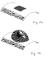
- FIG. 1a illustrates very clearly the advantages of an antenna according to the invention over a conventional antenna according to the illustration 1 b.
- FIG. 1a is a completely outer structure-compliant antenna subsystem, for example, for a broadband data link in the microwave range, shown.
- the integration of the antenna into the aircraft structure according to the invention avoids any aerodynamic disadvantages that could arise from an antenna with the greatest possible preservation of the structural strength.
- the antenna according to the invention based on a low reflection factor, has a large relative high-frequency bandwidth.
- the invention thus offers a real alternative to the conventional antennas, especially to the in Figure 1b shown reflector antennas, especially in the context of the invention comparable electronic properties be achieved at the same time significantly lower installation volume and lower mass.
- the invention provides, especially in aircraft structures additional arrangement areas for antennas, which are inaccessible to conventional antennas for various reasons.
- FIG. 2 shows an example of the structure of an antenna, for example in planar design according to the invention in its essential individual parts.
- the basis for the attachment of the antenna here forms a support structure 1 of an aircraft, which consists in many applications of CFRP.
- the actual electromagnetic (hereinafter referred to briefly as EM) functional core 2 of the antenna is connected to the carrier system primary structure 1 via a suitable adhesive layer 3.
- the essential upper or outer structure-adapted termination of the antenna is formed by a cover plate in the form of a so-called front dielectric 4, which is likewise connected to the electromagnetic functional core 2 via an adhesive layer 3.
- the cover plate is preferably formed of a fiber composite material having the following fiber / matrix combinations: fused silica / epoxy, E-glass / epoxy or Q-glass / polyester.
- the congruent bore rows 6 and 7 are openings for the electrical wiring of the outer structure-compliant antenna according to the invention.
- the total thickness of the antenna according to the invention is preferably a few millimeters, so that their integration into an aircraft structure means no or at most only a negligible structural interference.
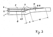
- the Figure 3 shows a possibility of optimal introduction or integration of an antenna in the support structure 1, for example in an aircraft.
- the support structure 1 has a trough 8 or a region-wise depression, which is brought about by acute-angled bending of the regions 9 and 10 of the support structure 1.
- obtuse-angled or stepwise transitions can also be realized;
- the region 9 of the support structure 1 could be bent downwards in an extreme case, so that the EM function core 2 could likewise be rectangular in its edge regions.
- the angle ⁇ should remain acute-angled, since its size depends on the size of the adhesive surface in the region 10 of the structure 1 for the corresponding bevelled part 11 of the front dielectric 4; the smaller, that is, the more acute the angle ⁇ is, the greater is the adhesive area in the area 10 of the support structure 1.
- the area 9 provides in radial view space for the accommodation of the EM function core 2, while the bending of the support structure 1 in the area 10 allows the load-bearing, outer contour-preserving gluing a cover plate in the form of a front dielectric 4.
Landscapes
- Physics & Mathematics (AREA)
- Engineering & Computer Science (AREA)
- Astronomy & Astrophysics (AREA)
- Aviation & Aerospace Engineering (AREA)
- General Physics & Mathematics (AREA)
- Remote Sensing (AREA)
- Details Of Aerials (AREA)
- Variable-Direction Aerials And Aerial Arrays (AREA)
Claims (3)
- Structure de support d'un véhicule avec une antenne épousant la forme de la structure extérieure,
dans laquelle l'antenne présente un noyau fonctionnel EM de forme plate (2), qui est logé dans une cuvette (8) de la structure de support (1);
une plaque de recouvrement (4), qui est réalisée sous la forme d'un couvercle supérieur ou extérieur, épousant la forme de la structure extérieure, du noyau fonctionnel EM (2), et qui est assemblée dans ses régions de bord (11) à la structure de support (1),
caractérisée en ce que le noyau fonctionnel EM (2) ainsi que la plaque de recouvrement (4) sont assemblés respectivement à la structure de support (1) au moyen d'une couche de colle (3), et en ce que la région de bord extérieure (10) de la cuvette (8) est formée en inclinant la structure de support (1) sous un sangle aigu (α) par rapport à la structure extérieure du véhicule, et en ce que la plaque de recouvrement (4) est biseautée de façon correspondante sous un angle aigu dans sa région de bord (11) et y est collée à la structure de support (1). - Structure de support d'un véhicule selon la revendication 1, caractérisée en ce que la plaque de recouvrement (4) est constituée d'un matériau diélectrique.
- Structure de support d'un véhicule selon la revendication 2, caractérisée en ce que la plaque de recouvrement (4) est constituée d'un matériau composite fibreux présentant une des combinaisons suivantes de fibres/matrice:- verre de quartz/époxy,- E-Glas/époxy,- Q-Glas/polyester.
Applications Claiming Priority (2)
| Application Number | Priority Date | Filing Date | Title |
|---|---|---|---|
| DE10356395A DE10356395A1 (de) | 2003-12-03 | 2003-12-03 | Außenstruktur-konforme Antenne in einer Trägerstruktur eines Fahrzeugs |
| DE10356395 | 2003-12-03 |
Publications (2)
| Publication Number | Publication Date |
|---|---|
| EP1538698A1 EP1538698A1 (fr) | 2005-06-08 |
| EP1538698B1 true EP1538698B1 (fr) | 2018-02-07 |
Family
ID=34442410
Family Applications (1)
| Application Number | Title | Priority Date | Filing Date |
|---|---|---|---|
| EP04028642.9A Expired - Lifetime EP1538698B1 (fr) | 2003-12-03 | 2004-12-03 | Antenne conformée dans le chassis d'un véhicule |
Country Status (3)
| Country | Link |
|---|---|
| US (1) | US7253777B2 (fr) |
| EP (1) | EP1538698B1 (fr) |
| DE (1) | DE10356395A1 (fr) |
Families Citing this family (18)
| Publication number | Priority date | Publication date | Assignee | Title |
|---|---|---|---|---|
| US20030096321A1 (en) * | 1999-05-19 | 2003-05-22 | Jose Remacle | Method for the identification and/or the quantification of a target compound obtained from a biological sample upon chips |
| IL154525A (en) * | 2003-02-18 | 2011-07-31 | Starling Advanced Comm Ltd | Low profile satellite communications antenna |
| US8427380B2 (en) | 2005-07-29 | 2013-04-23 | Foster-Miller, Inc. | Dual function composite system and method of making same |
| IL174549A (en) * | 2005-10-16 | 2010-12-30 | Starling Advanced Comm Ltd | Dual polarization planar array antenna and cell elements therefor |
| DE102005050204A1 (de) * | 2005-10-20 | 2007-04-26 | Eads Deutschland Gmbh | Verfahren zur Herstellung einer strukturintegrierten Antenne |
| DE102006005902B4 (de) * | 2006-02-09 | 2007-12-13 | Deutsches Zentrum für Luft- und Raumfahrt e.V. | Mehrschichtige Werkstoffverbundstruktur und Verfahren zur Herstellung hierzu |
| GB2461921B (en) | 2008-07-18 | 2010-11-24 | Phasor Solutions Ltd | A phased array antenna and a method of operating a phased array antenna |
| US9041594B2 (en) * | 2010-05-24 | 2015-05-26 | Honeywell International Inc. | RF based tracker for rotating objects |
| US9270016B2 (en) | 2011-07-15 | 2016-02-23 | The Boeing Company | Integrated antenna system |
| GB201215114D0 (en) | 2012-08-24 | 2012-10-10 | Phasor Solutions Ltd | Improvements in or relating to the processing of noisy analogue signals |
| CA2831325A1 (fr) | 2012-12-18 | 2014-06-18 | Panasonic Avionics Corporation | Calibrage de systeme d'antenne |
| CA2838861A1 (fr) | 2013-02-12 | 2014-08-12 | Panasonic Avionics Corporation | Optimisation d'antennes a profil bas pour utilisation a l'equateur |
| KR101366784B1 (ko) * | 2013-02-15 | 2014-02-21 | 국방과학연구소 | 대수주기 다이폴 배열 안테나 |
| US9705185B2 (en) * | 2013-04-11 | 2017-07-11 | Raytheon Company | Integrated antenna and antenna component |
| GB201403507D0 (en) | 2014-02-27 | 2014-04-16 | Phasor Solutions Ltd | Apparatus comprising an antenna array |
| RU2713050C1 (ru) * | 2019-01-28 | 2020-02-03 | Акционерное общество "Центральное конструкторское бюро автоматики" | Конформная спиральная антенна |
| DE102020102535A1 (de) | 2020-01-31 | 2021-08-05 | Airbus Operations Gmbh | Antennenanordnung für ein Flugzeug |
| US11145962B2 (en) * | 2020-03-05 | 2021-10-12 | GM Global Technology Operations LLC | Conformal antennas formed at a surface of a vehicle |
Family Cites Families (13)
| Publication number | Priority date | Publication date | Assignee | Title |
|---|---|---|---|---|
| JPS58120302A (ja) | 1982-01-11 | 1983-07-18 | Nissan Motor Co Ltd | 飛翔体搭載伝送線路型アンテナ装置 |
| DE3738513A1 (de) * | 1987-11-13 | 1989-06-01 | Dornier System Gmbh | Mikrostreifenleiterantenne |
| DE69020215T2 (de) * | 1989-04-03 | 1996-02-29 | Raytheon Co | Mikrostreifenleitungsantenne mit parasitären Elementen. |
| US5184141A (en) * | 1990-04-05 | 1993-02-02 | Vought Aircraft Company | Structurally-embedded electronics assembly |
| US5918183A (en) * | 1992-09-01 | 1999-06-29 | Trimble Navigation Limited | Concealed mobile communications system |
| US5414434A (en) * | 1993-08-24 | 1995-05-09 | Raytheon Company | Patch coupled aperature array antenna |
| SE9902949D0 (sv) | 1999-05-31 | 1999-08-19 | Allgon Ab | An antenna device and a piece of telecommunication equipment including such a device |
| JP3373180B2 (ja) * | 1999-08-31 | 2003-02-04 | 三星電子株式会社 | 携帯電話機 |
| US7113136B2 (en) * | 2000-12-18 | 2006-09-26 | Collins & Aikman Products Co. | Integrated dual function circuitry and antenna system |
| US6618014B2 (en) * | 2001-09-28 | 2003-09-09 | Centurion Wireless Tech., Inc. | Integral antenna and radio system |
| US6833815B2 (en) * | 2002-09-20 | 2004-12-21 | Bae Systems Information And Electronic Systems Integration Inc. | Cavity embedded meander line loaded antenna |
| JP2004179790A (ja) * | 2002-11-25 | 2004-06-24 | Yokowo Co Ltd | 車載アンテナ装置 |
| US6947008B2 (en) * | 2003-01-31 | 2005-09-20 | Ems Technologies, Inc. | Conformable layered antenna array |
-
2003
- 2003-12-03 DE DE10356395A patent/DE10356395A1/de not_active Ceased
-
2004
- 2004-12-02 US US11/000,916 patent/US7253777B2/en not_active Expired - Lifetime
- 2004-12-03 EP EP04028642.9A patent/EP1538698B1/fr not_active Expired - Lifetime
Non-Patent Citations (1)
| Title |
|---|
| None * |
Also Published As
| Publication number | Publication date |
|---|---|
| DE10356395A1 (de) | 2005-09-15 |
| EP1538698A1 (fr) | 2005-06-08 |
| US20050156786A1 (en) | 2005-07-21 |
| US7253777B2 (en) | 2007-08-07 |
Similar Documents
| Publication | Publication Date | Title |
|---|---|---|
| EP1538698B1 (fr) | Antenne conformée dans le chassis d'un véhicule | |
| DE60031446T2 (de) | Konforme lasttrag-antennenstruktur | |
| DE69201885T2 (de) | Gruppenantenne, insbesondere zur Verwendung im Weltraum. | |
| DE3788416T2 (de) | Modulbauförmige antennengruppe. | |
| DE102016101583B4 (de) | Radom | |
| DE10335216B4 (de) | Im Bereich einer Außenfläche eines Fluggeräts angeordnete phasengesteuerte Antenne | |
| WO2005117206A1 (fr) | Boitier d'antenne et antenne comprenant un tel boitier d'antenne | |
| DE3429417A1 (de) | Reflektorkonstruktion fuer elektromagnetische strahlung | |
| DE3333951A1 (de) | Antennenhalterung | |
| EP2747202A1 (fr) | Paroi d'un radôme | |
| DE4330736A1 (de) | Hochfrequenzleitende Konstruktionen | |
| DE69619153T2 (de) | Verbundwerkstoffstruktur, fähig zur Absorption und Dissipation von auffallender elektromagnetischer Strahlungsenergie, insbesondere für Luft-, See- und Landfahrzeuge und für feste Bodeneinrichtungen | |
| DE69212378T2 (de) | Antenne mit geformter Strahlungskeule und hohem Gewinn | |
| DE102007022616C5 (de) | Mehrschichtplatte mit schräger Schlitzung des Plattenkerns zur Reduzierung der Körperschallabstrahlung und zur Erhöhung der Schalldämmung bei Beibehalten der mechanischen Stabilität | |
| DE2339533A1 (de) | Kuenstliches dielektrikum zur steuerung von antennendiagrammen | |
| EP2485329B1 (fr) | Antenne groupée | |
| DE102017220732A1 (de) | Kraftfahrzeug mit einem Glasdach und mit einer auf diesem Glasdach aufsitzenden Antennenanordnung | |
| DE4035980A1 (de) | In der luft schwebendes fruehwarnradarsystem | |
| DE2830516C2 (de) | Selbsttragende, elektrisch reflexionsarme Abdeckung in Kugelform für Antennen | |
| DE3706974A1 (de) | Mikrostrip-antenne fuer doppler-navigatoren | |
| DE202006011919U1 (de) | Streifenleitungsantenne | |
| DE3632128C2 (fr) | ||
| EP3593987B1 (fr) | Composant acoustique | |
| DE69900503T2 (de) | Elektronische schaltungsstruktur mit optimisierung des platzbedarfs in abhangigkeit vom vorhandenen volumen | |
| DE102020102535A1 (de) | Antennenanordnung für ein Flugzeug |
Legal Events
| Date | Code | Title | Description |
|---|---|---|---|
| PUAI | Public reference made under article 153(3) epc to a published international application that has entered the european phase |
Free format text: ORIGINAL CODE: 0009012 |
|
| AK | Designated contracting states |
Kind code of ref document: A1 Designated state(s): AT BE BG CH CY CZ DE DK EE ES FI FR GB GR HU IE IS IT LI LT LU MC NL PL PT RO SE SI SK TR |
|
| AX | Request for extension of the european patent |
Extension state: AL BA HR LV MK YU |
|
| 17P | Request for examination filed |
Effective date: 20051110 |
|
| AKX | Designation fees paid |
Designated state(s): DE FI FR GB IT SE |
|
| 17Q | First examination report despatched |
Effective date: 20070531 |
|
| RAP1 | Party data changed (applicant data changed or rights of an application transferred) |
Owner name: AIRBUS DEFENCE AND SPACE GMBH |
|
| GRAP | Despatch of communication of intention to grant a patent |
Free format text: ORIGINAL CODE: EPIDOSNIGR1 |
|
| RIC1 | Information provided on ipc code assigned before grant |
Ipc: H01Q 1/32 20060101ALI20170526BHEP Ipc: H01Q 1/28 20060101AFI20170526BHEP |
|
| INTG | Intention to grant announced |
Effective date: 20170620 |
|
| GRAJ | Information related to disapproval of communication of intention to grant by the applicant or resumption of examination proceedings by the epo deleted |
Free format text: ORIGINAL CODE: EPIDOSDIGR1 |
|
| INTC | Intention to grant announced (deleted) | ||
| RIN1 | Information on inventor provided before grant (corrected) |
Inventor name: RITTER, JAN Inventor name: SEKORA, ROBERT Inventor name: ZIPPOLD, HERBERT Inventor name: NAGY, OLIVER, DR. Inventor name: BLASCHKE, DETLEV, DR. Inventor name: KAY, DITTRICH Inventor name: BRAND, CLEMENS, DR. |
|
| GRAP | Despatch of communication of intention to grant a patent |
Free format text: ORIGINAL CODE: EPIDOSNIGR1 |
|
| INTG | Intention to grant announced |
Effective date: 20171019 |
|
| GRAS | Grant fee paid |
Free format text: ORIGINAL CODE: EPIDOSNIGR3 |
|
| GRAA | (expected) grant |
Free format text: ORIGINAL CODE: 0009210 |
|
| AK | Designated contracting states |
Kind code of ref document: B1 Designated state(s): DE FI FR GB IT SE |
|
| REG | Reference to a national code |
Ref country code: GB Ref legal event code: FG4D Free format text: NOT ENGLISH |
|
| REG | Reference to a national code |
Ref country code: DE Ref legal event code: R096 Ref document number: 502004015644 Country of ref document: DE |
|
| REG | Reference to a national code |
Ref country code: SE Ref legal event code: TRGR |
|
| PG25 | Lapsed in a contracting state [announced via postgrant information from national office to epo] |
Ref country code: FI Free format text: LAPSE BECAUSE OF FAILURE TO SUBMIT A TRANSLATION OF THE DESCRIPTION OR TO PAY THE FEE WITHIN THE PRESCRIBED TIME-LIMIT Effective date: 20180207 |
|
| PG25 | Lapsed in a contracting state [announced via postgrant information from national office to epo] |
Ref country code: IT Free format text: LAPSE BECAUSE OF FAILURE TO SUBMIT A TRANSLATION OF THE DESCRIPTION OR TO PAY THE FEE WITHIN THE PRESCRIBED TIME-LIMIT Effective date: 20180207 |
|
| REG | Reference to a national code |
Ref country code: DE Ref legal event code: R097 Ref document number: 502004015644 Country of ref document: DE |
|
| PLBE | No opposition filed within time limit |
Free format text: ORIGINAL CODE: 0009261 |
|
| STAA | Information on the status of an ep patent application or granted ep patent |
Free format text: STATUS: NO OPPOSITION FILED WITHIN TIME LIMIT |
|
| 26N | No opposition filed |
Effective date: 20181108 |
|
| PGFP | Annual fee paid to national office [announced via postgrant information from national office to epo] |
Ref country code: GB Payment date: 20231220 Year of fee payment: 20 |
|
| PGFP | Annual fee paid to national office [announced via postgrant information from national office to epo] |
Ref country code: SE Payment date: 20231220 Year of fee payment: 20 Ref country code: FR Payment date: 20231221 Year of fee payment: 20 Ref country code: DE Payment date: 20231214 Year of fee payment: 20 |
|
| REG | Reference to a national code |
Ref country code: DE Ref legal event code: R071 Ref document number: 502004015644 Country of ref document: DE |
|
| REG | Reference to a national code |
Ref country code: GB Ref legal event code: PE20 Expiry date: 20241202 |
|
| PG25 | Lapsed in a contracting state [announced via postgrant information from national office to epo] |
Ref country code: GB Free format text: LAPSE BECAUSE OF EXPIRATION OF PROTECTION Effective date: 20241202 |
|
| REG | Reference to a national code |
Ref country code: SE Ref legal event code: EUG |
|
| PG25 | Lapsed in a contracting state [announced via postgrant information from national office to epo] |
Ref country code: GB Free format text: LAPSE BECAUSE OF EXPIRATION OF PROTECTION Effective date: 20241202 |