EP1538698B1 - Conformal antenna provided in the body of a vehicle - Google Patents
Conformal antenna provided in the body of a vehicle Download PDFInfo
- Publication number
- EP1538698B1 EP1538698B1 EP04028642.9A EP04028642A EP1538698B1 EP 1538698 B1 EP1538698 B1 EP 1538698B1 EP 04028642 A EP04028642 A EP 04028642A EP 1538698 B1 EP1538698 B1 EP 1538698B1
- Authority
- EP
- European Patent Office
- Prior art keywords
- antenna
- aircraft
- supporting structure
- antennas
- vehicle
- Prior art date
- Legal status (The legal status is an assumption and is not a legal conclusion. Google has not performed a legal analysis and makes no representation as to the accuracy of the status listed.)
- Active
Links
- 239000012790 adhesive layer Substances 0.000 claims description 5
- 239000004593 Epoxy Substances 0.000 claims description 4
- 239000011521 glass Substances 0.000 claims description 4
- 230000001154 acute effect Effects 0.000 claims description 3
- 239000000835 fiber Substances 0.000 claims description 3
- 238000007373 indentation Methods 0.000 claims description 3
- 239000002131 composite material Substances 0.000 claims description 2
- 239000011159 matrix material Substances 0.000 claims description 2
- 229920000728 polyester Polymers 0.000 claims description 2
- 230000002093 peripheral effect Effects 0.000 claims 3
- 239000003989 dielectric material Substances 0.000 claims 1
- 230000010354 integration Effects 0.000 description 8
- 239000010410 layer Substances 0.000 description 3
- 235000015842 Hesperis Nutrition 0.000 description 2
- 235000012633 Iberis amara Nutrition 0.000 description 2
- 239000000853 adhesive Substances 0.000 description 2
- 230000001070 adhesive effect Effects 0.000 description 2
- 238000005452 bending Methods 0.000 description 2
- 230000005540 biological transmission Effects 0.000 description 2
- 230000001419 dependent effect Effects 0.000 description 2
- 238000009434 installation Methods 0.000 description 2
- 238000009751 slip forming Methods 0.000 description 2
- VYPSYNLAJGMNEJ-UHFFFAOYSA-N Silicium dioxide Chemical compound O=[Si]=O VYPSYNLAJGMNEJ-UHFFFAOYSA-N 0.000 description 1
- 230000004308 accommodation Effects 0.000 description 1
- 238000004026 adhesive bonding Methods 0.000 description 1
- 230000002411 adverse Effects 0.000 description 1
- 238000003491 array Methods 0.000 description 1
- 239000004303 calcium sorbate Substances 0.000 description 1
- 239000004918 carbon fiber reinforced polymer Substances 0.000 description 1
- 238000010276 construction Methods 0.000 description 1
- 238000009429 electrical wiring Methods 0.000 description 1
- 239000005350 fused silica glass Substances 0.000 description 1
- 238000011835 investigation Methods 0.000 description 1
- 239000000463 material Substances 0.000 description 1
- 238000004321 preservation Methods 0.000 description 1
- 230000000717 retained effect Effects 0.000 description 1
- 230000007704 transition Effects 0.000 description 1
Images

Classifications
-
- H—ELECTRICITY
- H01—ELECTRIC ELEMENTS
- H01Q—ANTENNAS, i.e. RADIO AERIALS
- H01Q1/00—Details of, or arrangements associated with, antennas
- H01Q1/27—Adaptation for use in or on movable bodies
- H01Q1/28—Adaptation for use in or on aircraft, missiles, satellites, or balloons
- H01Q1/286—Adaptation for use in or on aircraft, missiles, satellites, or balloons substantially flush mounted with the skin of the craft
-
- H—ELECTRICITY
- H01—ELECTRIC ELEMENTS
- H01Q—ANTENNAS, i.e. RADIO AERIALS
- H01Q1/00—Details of, or arrangements associated with, antennas
- H01Q1/27—Adaptation for use in or on movable bodies
- H01Q1/32—Adaptation for use in or on road or rail vehicles
Definitions
- the invention relates to the support structure of a vehicle, in particular of an aircraft, with an outer structure-compliant antenna and in particular a flat broadband antenna and, wherein the support structure is in particular a primary structure.
- aircraft refers to all conceivable devices that can be moved with any drives through the air, such as aircraft, helicopters, airships, drones, rockets and the like.
- the rockets are an example of how the invention may also relate to aircraft or missiles capable of flying both in the air and in a vacuum.
- Air-supported pivotable reflector antennas are currently available as commercial products. However, their housing is usually a problem. It has therefore already been considered, instead of using a relatively large reflector antenna parts, for example, the aircraft surface as a radiating aperture.
- the US 5,184,141 describes a multilayer carrier structure with an integrated outer structure-compliant antenna of an aircraft.
- the antenna is arranged between two adjacent layers, wherein the inwardly directed layer may be an adhesive layer.
- a further outer structure-compliant antenna is described, which is incorporated in the trough of a support structure.
- the antenna is covered with a cover plate which is fixed with a circumferential nose, which engages in a groove provided on the support structure.
- the cover plate is continuously formed as a plane-parallel plate, which rests at their edges on a support surface of the support structure, which is parallel to the outer contour.
- the invention has the object of integrating outer structure-compliant antennas in such a way in the support structures of vehicles and / or aircraft, that any aerodynamic disadvantages are avoided and the structural strength is largely retained in the integration areas, while ensuring the antenna functionality.
- an outer structure-compliant antenna in the form of a flat EM function core is frictionally embedded in a corresponding indentation of a support structure in such a way that the upper or outer cover of the antenna is realized in outer structure conformity by a cover plate, which in turn also frictionally engages in its edge regions connected to the support structure.
- the frictional connection is realized by an adhesive layer.
- the above-mentioned cover plate is advantageous for antenna-technical reasons designed as a so-called front dielectric.
- the invention thus offers significant weight and volume savings over conventional antenna designs, which are particularly advantageous for aircraft. Aerodynamic disadvantages can not occur at all within the scope of the invention, since the shape of the outer skin of the structures remains completely unchanged. Practical investigations have in the meantime shown that the structural strength is at best influenced to a negligible extent by the invention.
- structure-integrated antennas according to the invention offer the possibility of arrangement in areas which up to now have been unacceptable or even unsuitable for conventional antennas.
- antennas can be installed and also in refueled structures when appropriate precautions are taken in terms of high-frequency lines.
- the structural integration of the antenna according to the invention leads to a considerable potential with regard to the reduction of the radar signature compared to conventional antenna designs.
- the antennas according to the invention are also suitable for use in stealth aircraft (stealth aircraft).
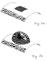
- FIG. 1a illustrates very clearly the advantages of an antenna according to the invention over a conventional antenna according to the illustration 1 b.
- FIG. 1a is a completely outer structure-compliant antenna subsystem, for example, for a broadband data link in the microwave range, shown.
- the integration of the antenna into the aircraft structure according to the invention avoids any aerodynamic disadvantages that could arise from an antenna with the greatest possible preservation of the structural strength.
- the antenna according to the invention based on a low reflection factor, has a large relative high-frequency bandwidth.
- the invention thus offers a real alternative to the conventional antennas, especially to the in Figure 1b shown reflector antennas, especially in the context of the invention comparable electronic properties be achieved at the same time significantly lower installation volume and lower mass.
- the invention provides, especially in aircraft structures additional arrangement areas for antennas, which are inaccessible to conventional antennas for various reasons.
- FIG. 2 shows an example of the structure of an antenna, for example in planar design according to the invention in its essential individual parts.
- the basis for the attachment of the antenna here forms a support structure 1 of an aircraft, which consists in many applications of CFRP.
- the actual electromagnetic (hereinafter referred to briefly as EM) functional core 2 of the antenna is connected to the carrier system primary structure 1 via a suitable adhesive layer 3.
- the essential upper or outer structure-adapted termination of the antenna is formed by a cover plate in the form of a so-called front dielectric 4, which is likewise connected to the electromagnetic functional core 2 via an adhesive layer 3.
- the cover plate is preferably formed of a fiber composite material having the following fiber / matrix combinations: fused silica / epoxy, E-glass / epoxy or Q-glass / polyester.
- the congruent bore rows 6 and 7 are openings for the electrical wiring of the outer structure-compliant antenna according to the invention.
- the total thickness of the antenna according to the invention is preferably a few millimeters, so that their integration into an aircraft structure means no or at most only a negligible structural interference.
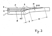
- the Figure 3 shows a possibility of optimal introduction or integration of an antenna in the support structure 1, for example in an aircraft.
- the support structure 1 has a trough 8 or a region-wise depression, which is brought about by acute-angled bending of the regions 9 and 10 of the support structure 1.
- obtuse-angled or stepwise transitions can also be realized;
- the region 9 of the support structure 1 could be bent downwards in an extreme case, so that the EM function core 2 could likewise be rectangular in its edge regions.
- the angle ⁇ should remain acute-angled, since its size depends on the size of the adhesive surface in the region 10 of the structure 1 for the corresponding bevelled part 11 of the front dielectric 4; the smaller, that is, the more acute the angle ⁇ is, the greater is the adhesive area in the area 10 of the support structure 1.
- the area 9 provides in radial view space for the accommodation of the EM function core 2, while the bending of the support structure 1 in the area 10 allows the load-bearing, outer contour-preserving gluing a cover plate in the form of a front dielectric 4.
Description
Die Erfindung bezieht sich auf die Trägerstruktur eines Fahrzeugs, insbesondere eines Fluggeräts, mit einer außenstruktur-konforme Antenne und insbesondere einer flachen Breitbandantenne und, wobei die Trägerstruktur insbesondere eine Primärstruktur ist.The invention relates to the support structure of a vehicle, in particular of an aircraft, with an outer structure-compliant antenna and in particular a flat broadband antenna and, wherein the support structure is in particular a primary structure.
Der Begriff "Fluggeräte" betrifft alle nur denkbaren Geräte, die mit beliebigen Antrieben durch die Luft bewegt werden können, wie Flugzeuge, Hubschrauber, Luftschiffe, Drohnen, Raketen und dergleichen. Die Raketen sind ein Beispiel dafür, dass die Erfindung auch Fluggeräte bzw. Flugkörper betreffen kann, die geeignet sind, sowohl in der Luft als auch im luftleeren Raum zu fliegen.The term "aircraft" refers to all conceivable devices that can be moved with any drives through the air, such as aircraft, helicopters, airships, drones, rockets and the like. The rockets are an example of how the invention may also relate to aircraft or missiles capable of flying both in the air and in a vacuum.
Die zunehmende Anzahl von Avionikfunktionen bei Fluggeräten, im besonderen bei Flugzeugen lässt auch die erforderliche Anzahl von Antennen entsprechend ansteigen; bis zu sechzig Antennensysteme und mehr sind bereits heute keine Seltenheit mehr. Diese Problematik erfordert neue Wege für den Einbau bzw. die Unterbringung von Antennen beispielsweise bei Flugzeugen. Eine mögliche Lösung dieses Problems ist die Integration der Antennen in die Trägerstrukturen von Fahrzeugen und/oder Fluggeräten.The increasing number of avionics functions in aircraft, in particular aircraft, is also causing the required number of antennas to increase accordingly; Up to sixty antenna systems and more are no longer a rarity today. This problem requires new ways for the installation or placement of antennas, for example, in aircraft. One possible solution to this problem is the integration of the antennas into the support structures of vehicles and / or aircraft.
Bei der Lösung der aufgezeigten Problematik ist auch zu bedenken, dass der Einsatz künftiger luftgestützter Datenübertragungssysteme wegen immenser Datenmengen eine große HF-Bandbreite erfordert. Aus diesem Grund kommen immer höhere Frequenzen zur Anwendung. Der Markt bietet derzeit überwiegend Systeme im X- oder Ku-Band an.When solving the problems outlined, it should also be borne in mind that the use of future airborne data transmission systems requires a large HF bandwidth due to the immense amount of data. For this reason, ever higher frequencies are used. The market currently mainly offers systems in the X or Ku band.
Neben der Forderung nach einer großen Bandbreite wird naturgemäß eine große Reichweite für die Datenübertragung gefordert. Dies kann nur durch Antennen mit entsprechend großer Apertur oder mit Arrays erreicht werden, die aus mehreren Einzelstrahlern bestehen. Luftgestützte schwenkbare Reflektorantennen sind derzeit als kommerzielle Produkte erhältlich. Deren Unterbringung ist jedoch meistens ein Problem. Es wurde daher auch schon überlegt, anstatt einer relativ großen Reflektorantenne Teile beispielsweise der Flugzeugoberfläche als strahlende Apertur zu nutzen.In addition to the demand for a large bandwidth naturally a large range for data transmission is required. This can only be achieved by means of antennas with a correspondingly large aperture or with arrays consisting of several individual radiators. Air-supported pivotable reflector antennas are currently available as commercial products. However, their housing is usually a problem. It has therefore already been considered, instead of using a relatively large reflector antenna parts, for example, the aircraft surface as a radiating aperture.
Bislang hatte zum Beispiel eine Flugzeugstruktur ausschließlich die Funktion, lasttragende und aerodynamische Aufgaben zu übernehmen. Die strukturelle Oberfläche musste dementsprechend verschiedene mechanische Belastungen aushalten.So far, for example, an aircraft structure had only the function to take over load-bearing and aerodynamic tasks. The structural surface had to withstand various mechanical loads accordingly.
Mit der Funktionserweiterung der Strukturoberfläche von Fluggeräten auch als Antenne wirksam zu werden ergeben sich zusätzliche Probleme hinsichtlich der Stabilität der Strukturen. Elektronisch bedingt müssen für die Antennen geeignete Materialien eingesetzt werden; dabei darf aber die lasttragende Funktion der Struktur nicht negativ beeinflusst werden.With the functional extension of the structure surface of aircraft as an antenna to be effective additional problems arise with respect to the stability of the structures. For electronic reasons, suitable materials must be used for the antennas; however, the load-bearing function of the structure must not be adversely affected.
Aus den eingangs genannten Gründen geht die Fachwelt mehr und mehr davon ab, Antennen zu bauen bzw. anzuwenden, die sich in Form von Stäben, Spiralen, Hornteilen oder anderen Gebilden von der Struktur bzw. der Außenhaut von Fahrzeugen und/oder Fluggeräten abheben. Dadurch können Strömungswiderstände verringert und die Gefahr von rein mechanischen Beschädigungen der Antennen zumindest das reduziert werden.For the reasons mentioned above, experts are more and more reluctant to build or use antennas that stand out in the form of rods, spirals, horn parts or other structures from the structure or the outer skin of vehicles and / or aircraft. As a result, flow resistance can be reduced and the risk of purely mechanical damage to the antennas can be reduced at least.
Die zitierte Problematik hat dazu geführt, außenstruktur-konforme Antennen zu entwickeln und diese weitmöglich bzw. optimal, das heißt identisch der vorgegebenen Form von Strukturen bei Fahrzeugen und/oder Fluggeräten anzupassen.The quoted problem has led to develop outer structure-compliant antennas and adapt them as far as possible or optimal, that is identical to the given form of structures in vehicles and / or aircraft.
Zum diesbezüglich bekannten Stand der Technik sei verwiesen auf eine Publikation von Dipl.-Ing. Robert Sekora u.a. unter dem Titel: "Conformal Airborne Array Antenna for Broad Band Data Link Applications in the X-Band". Diese Abhandlung zeigt im Wesentlichen die Unterschiede auf zwischen herkömmlichen und aktuelleren außenstruktur-konformen Antennensystemen, die eng an die Struktur - in diesem Falle von Flugzeugen - angepasst sind.For related prior art reference is made to a publication by Dipl.-Ing. Robert Sekora et al. Entitled "Conformal Airborne Array Antenna for Broadband Data Link Applications in the X-Band". This essay essentially shows the differences between conventional ones and more recent exterior structure compliant antenna systems that are closely matched to the structure - in this case, aircraft.
Eine weitere einschlägige Vorveröffentlichung ist ein Aufsatz, ebenfalls von Dipl.-Ing. Robert Sekora, unter dem Titel: "Strukturintegrierte Flugzeugantenne für Breitbandanwendungen im X-Band". Der Autor erklärt in dieser Publikation die strukturelle Integrierbarkeit einer Array-Antenne. Des Weiteren wird der strukturelle Aufbau hinsichtlich seiner elektromagnetischen Funktion bestätigt.Another relevant pre-publication is an essay, also by Dipl.-Ing. Robert Sekora, under the title: "Structurally Integrated Aircraft Antenna for Broadband Applications in the X-Band". The author explains in this publication the structural integrability of an array antenna. Furthermore, the structural design is confirmed in terms of its electromagnetic function.
Die
In Patent Abstracts of Japan Bd. 007, Nr. 229 (E-203), 12. Oktober 1983 und der zugehörigen
In der
Der Erfindung liegt die Aufgabe zugrunde, außenstruktur-konforme Antennen derart in die Trägerstrukturen von Fahrzeugen und/oder Fluggeräten zu integrieren, dass jegliche aerodynamischen Nachteile vermieden werden und die Strukturfestigkeit in den Integrationsbereichen weitestgehend erhalten bleibt, bei gleichzeitiger Gewährleistung der Antennen-Funktionalität.The invention has the object of integrating outer structure-compliant antennas in such a way in the support structures of vehicles and / or aircraft, that any aerodynamic disadvantages are avoided and the structural strength is largely retained in the integration areas, while ensuring the antenna functionality.
Erfindungsgemäß wird die Aufgabe mit den Merkmalen des Patentanspruchs 1 gelöst. Weitere Ausführungsformen sind in den auf diese rückbezogenen Unteransprüchen angegeben.According to the invention the object is achieved with the features of
Erfindungsgemäß ist eine außenstruktur-konforme Antenne in Form eines flach ausgebildeten EM-Funktionskerns in eine entsprechende Einbuchtung einer Trägerstruktur kraftschlüssig derart eingebettet, dass die obere bzw. äußere Abdeckung der Antenne außenstruktur-konform durch eine Abdeckplatte realisiert ist, welche ihrerseits in ihren Randbereichen ebenfalls kraftschlüssig mit der Trägerstruktur verbunden ist.According to the invention, an outer structure-compliant antenna in the form of a flat EM function core is frictionally embedded in a corresponding indentation of a support structure in such a way that the upper or outer cover of the antenna is realized in outer structure conformity by a cover plate, which in turn also frictionally engages in its edge regions connected to the support structure.
Die kraftschlüssige Verbindung wird durch eine Kleberschicht realisiert.The frictional connection is realized by an adhesive layer.
Die oben erwähnte Abdeckplatte ist aus antennen-technischen Gründen vorteilhaft als sogenanntes Frontdielektrikum ausgebildet.The above-mentioned cover plate is advantageous for antenna-technical reasons designed as a so-called front dielectric.
Die Erfindung bietet damit gegenüber konventionellen Antennenkonstruktionen signifikante Gewichts- und Volumeneinsparungen, die sich besonders vorteilhaft bei Flugzeugen auswirken. Aerodynamische Nachteile können im Rahmen der Erfindung überhaupt nicht auftreten, da die Form der Außenhaut der Strukturen vollends unverändert erhalten bleibt. Praktische Untersuchungen haben inzwischen ergeben, dass die Strukturfestigkeit durch die Erfindung allenfalls in vernachlässigbar geringem Umfang beeinflusst wird.The invention thus offers significant weight and volume savings over conventional antenna designs, which are particularly advantageous for aircraft. Aerodynamic disadvantages can not occur at all within the scope of the invention, since the shape of the outer skin of the structures remains completely unchanged. Practical investigations have in the meantime shown that the structural strength is at best influenced to a negligible extent by the invention.
Des weiteren bieten strukturintegrierte Antennen gemäss der Erfindung vor allem bei Fluggeräten die Möglichkeit der Anordnung in Bereichen, die bislang für herkömmliche Antennen nicht vertretbar oder gar ungeeignet waren. Darüber hinaus können durch die Erfindung beim Flugzeug in Ruder- oder Klappenstrukturen Antennen eingebaut werden und auch in betankte Strukturen, wenn hinsichtlich der Hochfrequenzleitungen entsprechende Vorsichtsmassnahmen getroffen werden.In addition, structure-integrated antennas according to the invention, especially in the case of aircraft, offer the possibility of arrangement in areas which up to now have been unacceptable or even unsuitable for conventional antennas. In addition, by the invention in the aircraft in rudder or flap structures antennas can be installed and also in refueled structures when appropriate precautions are taken in terms of high-frequency lines.
In elektronischer Hinsicht führt die erfindungsgemäße Strukturintegration der Antenne zu einem beachtlichen Potential hinsichtlich der Reduktion der Radarsignatur gegenüber herkömmlichen Antennenbauweisen. Hierdurch bieten sich die erfindungsgemäßen Antennen auch für den Einsatz bei Tarnkappenflugzeugen (Stealth-Fluggeräte) an.From an electronic point of view, the structural integration of the antenna according to the invention leads to a considerable potential with regard to the reduction of the radar signature compared to conventional antenna designs. As a result, the antennas according to the invention are also suitable for use in stealth aircraft (stealth aircraft).
Grundsätzlich kann nicht zuletzt auch festgestellt werden, dass die elektronischen respektive die elektromagnetischen Eigenschaften der erfindungsgemäßen Antennenkonstruktion den an sie gestellten Erwartungen bzw. Anforderungen vollends gerecht werden.Basically, not least, it can also be stated that the electronic or the electromagnetic properties of the antenna construction according to the invention fully meet the expectations and requirements imposed on them.
Weitere vorteilhafte Ausgestaltungen der Erfindung ergeben sich aus den weiteren Ansprüchen sowie aus der Abbildungsbeschreibung.Further advantageous embodiments of the invention will become apparent from the other claims and from the illustration.
In den Abbildungen ist die Erfindung anhand eines Ausführungsbeispiels zeichnerisch erläutert.In the figures, the invention is explained with reference to an exemplary embodiment.
Es zeigen:
-
Figur 1a eine Draufsicht auf eine strukturintegrierte, außenstruktur-konforme Antenne; -
Figur 1b ein Beispiel für ausschließlich kommerziell verfügbare, unförmige, mechanisch schwenkbare, zentral gespeiste Reflektor-Antenne; -
Figur 2 -
Figur 3Figur 2
-
FIG. 1a a plan view of a structurally integrated, outer structure-compliant antenna; -
FIG. 1b an example of exclusively commercially available, bulky, mechanically pivotable, centrally fed reflector antenna; -
FIG. 2 a structure design for an outer structure-compliant antenna, as used in the invention; -
FIG. 3 the integration according to the invention of an outer structure-compliant antenna according toFIG. 2 in an aircraft carrier structure.
Elektronisch gesehen verfügt die erfindungsgemäße Antenne, bezogen auf einen geringen Reflexionsfaktor, über eine große relative Hochfrequenzbandbreite.Seen electronically, the antenna according to the invention, based on a low reflection factor, has a large relative high-frequency bandwidth.
Die Erfindung bietet damit eine echte Alternative zu den herkömmlichen Antennen, vor allem auch zu den in
Die Abdeckplatte ist vorzugsweise aus einem Faserverbundmaterial mit folgenden Kombinationen aus Faser/Matrix gebildet: Quarzglas/Epoxy, E-Glas/Epoxy oder Q-Glas/Polyester.The cover plate is preferably formed of a fiber composite material having the following fiber / matrix combinations: fused silica / epoxy, E-glass / epoxy or Q-glass / polyester.
Bei den deckungsgleichen Bohrungsreihen 6 und 7 handelt es sich um Durchbrüche für die elektrische Verkabelung der erfindungsgemäßen außenstruktur-konformen Antenne.The
Die Gesamtdicke der erfindungsgemäßen Antenne beträgt vorzugsweise einige Millimeter, so dass deren Integration in eine Flugzeugstruktur keine oder allenfalls nur eine vernachlässigbar geringe Strukturbeeinflussung bedeutet.The total thickness of the antenna according to the invention is preferably a few millimeters, so that their integration into an aircraft structure means no or at most only a negligible structural interference.
Die
Demgegenüber sollte im Rahmen der Erfindung der Winkel α spitzwinklig bleiben, da von seiner Bemessung die Größe der Klebefläche im Bereich 10 der struktur 1 für den entsprechend abgeschrägten Teil 11 des Frontdielektrikums 4 abhängt; je kleiner, das heißt je spitzwinkliger der Winkel α ist, umso größer wird die Klebefläche im Bereich 10 der Trägerstruktur 1.In contrast, in the context of the invention, the angle α should remain acute-angled, since its size depends on the size of the adhesive surface in the
Der Bereich 9 liefert in radialer Sicht Raum für die Unterbringung des EM-Funktionskerns 2, während das Einbiegen der Trägerstruktur 1 im Bereich 10 das lasttragende, außenkontur-erhaltende Einkleben einer Abdeckplatte in Form eines Frontdielektrikums 4 ermöglicht.The
Claims (3)
- Supporting structure of a vehicle with an antenna that is conformal with the outer structure,
wherein the antenna has a flat-formed EM functional core (2), which is embedded in an indentation (8) of the supporting structure (1);
a covering plate (4), which is formed as an upper or outer covering of the EM functional core (2) that is conformal with the outer structure and which is connected in its peripheral regions (11) to the supporting structure (1),
characterized in that
the EM functional core (2) and also the covering plate (4) are respectively connected to the supporting structure (1) by way of an adhesive layer (3) and
in that the outer peripheral region (10) of the indentation (8) is formed by angling of the supporting structure (1) at an acute angle (α) with respect to the outer structure of the vehicle, and in that the covering plate (4) is correspondingly bevelled on its peripheral legion (11) at an acute angle and adhesively bonded there to the supporting structure (1). - Supporting structure of a vehicle according to Claim 1, characterized in that the covering plate (4) is formed from a dielectric material.
- Supporting structure of a vehicle according to Claim 2, characterized in that the covering plate (4) is formed from a fibre-composite material comprising one of the following combinations of fibre/matrix:- quartz glass/epoxy,- E glass/epoxy,- Q glass/polyester.
Applications Claiming Priority (2)
| Application Number | Priority Date | Filing Date | Title |
|---|---|---|---|
| DE10356395 | 2003-12-03 | ||
| DE10356395A DE10356395A1 (en) | 2003-12-03 | 2003-12-03 | Exterior structure-compliant antenna in a support structure of a vehicle |
Publications (2)
| Publication Number | Publication Date |
|---|---|
| EP1538698A1 EP1538698A1 (en) | 2005-06-08 |
| EP1538698B1 true EP1538698B1 (en) | 2018-02-07 |
Family
ID=34442410
Family Applications (1)
| Application Number | Title | Priority Date | Filing Date |
|---|---|---|---|
| EP04028642.9A Active EP1538698B1 (en) | 2003-12-03 | 2004-12-03 | Conformal antenna provided in the body of a vehicle |
Country Status (3)
| Country | Link |
|---|---|
| US (1) | US7253777B2 (en) |
| EP (1) | EP1538698B1 (en) |
| DE (1) | DE10356395A1 (en) |
Families Citing this family (18)
| Publication number | Priority date | Publication date | Assignee | Title |
|---|---|---|---|---|
| US20030096321A1 (en) * | 1999-05-19 | 2003-05-22 | Jose Remacle | Method for the identification and/or the quantification of a target compound obtained from a biological sample upon chips |
| IL154525A (en) * | 2003-02-18 | 2011-07-31 | Starling Advanced Comm Ltd | Low profile antenna for satellite communication |
| WO2007016642A2 (en) * | 2005-07-29 | 2007-02-08 | Foster-Miller, Inc. | Dual function composite system and method of making same |
| IL174549A (en) * | 2005-10-16 | 2010-12-30 | Starling Advanced Comm Ltd | Dual polarization planar array antenna and cell elements therefor |
| DE102005050204A1 (en) * | 2005-10-20 | 2007-04-26 | Eads Deutschland Gmbh | Integrated aircraft antenna manufacturing process uses primary structure antenna preform from fibre containing dry prepreg comprising layers with several flexible conducting antenna elements |
| DE102006005902B4 (en) * | 2006-02-09 | 2007-12-13 | Deutsches Zentrum für Luft- und Raumfahrt e.V. | Multilayer composite material structure and method for the production of this |
| GB2461921B (en) | 2008-07-18 | 2010-11-24 | Phasor Solutions Ltd | A phased array antenna and a method of operating a phased array antenna |
| US9041594B2 (en) * | 2010-05-24 | 2015-05-26 | Honeywell International Inc. | RF based tracker for rotating objects |
| US9270016B2 (en) | 2011-07-15 | 2016-02-23 | The Boeing Company | Integrated antenna system |
| GB201215114D0 (en) | 2012-08-24 | 2012-10-10 | Phasor Solutions Ltd | Improvements in or relating to the processing of noisy analogue signals |
| CA2831325A1 (en) | 2012-12-18 | 2014-06-18 | Panasonic Avionics Corporation | Antenna system calibration |
| CA2838861A1 (en) | 2013-02-12 | 2014-08-12 | Panasonic Avionics Corporation | Optimization of low profile antenna(s) for equatorial operation |
| KR101366784B1 (en) * | 2013-02-15 | 2014-02-21 | 국방과학연구소 | Log-periodic dipole array antenna |
| US9705185B2 (en) * | 2013-04-11 | 2017-07-11 | Raytheon Company | Integrated antenna and antenna component |
| GB201403507D0 (en) | 2014-02-27 | 2014-04-16 | Phasor Solutions Ltd | Apparatus comprising an antenna array |
| RU2713050C1 (en) * | 2019-01-28 | 2020-02-03 | Акционерное общество "Центральное конструкторское бюро автоматики" | Conformal spiral antenna |
| DE102020102535A1 (en) | 2020-01-31 | 2021-08-05 | Airbus Operations Gmbh | Antenna arrangement for an aircraft |
| US11145962B2 (en) * | 2020-03-05 | 2021-10-12 | GM Global Technology Operations LLC | Conformal antennas formed at a surface of a vehicle |
Family Cites Families (13)
| Publication number | Priority date | Publication date | Assignee | Title |
|---|---|---|---|---|
| JPS58120302A (en) | 1982-01-11 | 1983-07-18 | Nissan Motor Co Ltd | Transmission line type antenna device mounted on flying object |
| DE3738513A1 (en) * | 1987-11-13 | 1989-06-01 | Dornier System Gmbh | MICROSTRIP LADDER AERIAL |
| DE69020215T2 (en) * | 1989-04-03 | 1996-02-29 | Raytheon Co | Microstrip line antenna with parasitic elements. |
| US5184141A (en) | 1990-04-05 | 1993-02-02 | Vought Aircraft Company | Structurally-embedded electronics assembly |
| US5918183A (en) * | 1992-09-01 | 1999-06-29 | Trimble Navigation Limited | Concealed mobile communications system |
| US5414434A (en) * | 1993-08-24 | 1995-05-09 | Raytheon Company | Patch coupled aperature array antenna |
| SE9902949D0 (en) | 1999-05-31 | 1999-08-19 | Allgon Ab | An antenna device and a piece of telecommunication equipment including such a device |
| JP3373180B2 (en) * | 1999-08-31 | 2003-02-04 | 三星電子株式会社 | Mobile phone |
| AU2002234045A1 (en) * | 2000-12-18 | 2002-07-01 | Textron Automotive Company Inc. | Integrated dual function circuitry and antenna system |
| US6618014B2 (en) * | 2001-09-28 | 2003-09-09 | Centurion Wireless Tech., Inc. | Integral antenna and radio system |
| US6833815B2 (en) * | 2002-09-20 | 2004-12-21 | Bae Systems Information And Electronic Systems Integration Inc. | Cavity embedded meander line loaded antenna |
| JP2004179790A (en) * | 2002-11-25 | 2004-06-24 | Yokowo Co Ltd | On-vehicle antenna system |
| US6947008B2 (en) * | 2003-01-31 | 2005-09-20 | Ems Technologies, Inc. | Conformable layered antenna array |
-
2003
- 2003-12-03 DE DE10356395A patent/DE10356395A1/en not_active Ceased
-
2004
- 2004-12-02 US US11/000,916 patent/US7253777B2/en active Active
- 2004-12-03 EP EP04028642.9A patent/EP1538698B1/en active Active
Non-Patent Citations (1)
| Title |
|---|
| None * |
Also Published As
| Publication number | Publication date |
|---|---|
| US7253777B2 (en) | 2007-08-07 |
| EP1538698A1 (en) | 2005-06-08 |
| US20050156786A1 (en) | 2005-07-21 |
| DE10356395A1 (en) | 2005-09-15 |
Similar Documents
| Publication | Publication Date | Title |
|---|---|---|
| EP1538698B1 (en) | Conformal antenna provided in the body of a vehicle | |
| DE60031446T2 (en) | CONFORMITY LOAD TRACK ANTENNA STRUCTURE | |
| DE102016101583B4 (en) | Radom | |
| DE102008008675B4 (en) | Radar device for a missile, in particular for a drone | |
| DE102007062111A1 (en) | Shielding arrangement for lightning protection of e.g. electrical conductor, in aircraft, has installation space protectively arranged in region of floor framework, and delimitation surface provided with electrical conducting shield | |
| DE10335216B4 (en) | In the area of an outer surface of an aircraft arranged phased array antenna | |
| WO2005117206A1 (en) | Antenna housing and antenna comprising such an antenna housing | |
| EP0817311A2 (en) | Feed assembly with a dielectric radiator for a parabolic reflector antenna | |
| DE102018109723A1 (en) | Antenna arrangement for an aircraft | |
| DE3429417A1 (en) | REFLECTOR CONSTRUCTION FOR ELECTROMAGNETIC RADIATION | |
| DE2711313A1 (en) | LIGHT RF ANTENNA | |
| DE3333951A1 (en) | ANTENNA MOUNT | |
| DE202006011919U1 (en) | Strip-line antenna e.g. patch antenna, has substrate structure whose base surface leads up to edges of the antenna and designed like frame, i.e. with centrical hollow, and metal layers consisting of metal foils | |
| DE4330736A1 (en) | High frequency conductive constructions | |
| EP2747202A1 (en) | Radome wall | |
| DE2339533A1 (en) | ARTIFICIAL DIELECTRIC FOR CONTROL OF ANTENNA DIAGRAMS | |
| DE4035980A1 (en) | Airborne early warning radar system - uses phase controlled antenna mounted in plastic composite bodied pilotless aircraft | |
| DE2830516C2 (en) | Self-supporting, electrically reflective spherical cover for antennas | |
| DE3706974A1 (en) | MICROSTRIP ANTENNA FOR DOPPLER NAVIGATORS | |
| EP2485329B1 (en) | Array antenna | |
| EP3486997A1 (en) | Motor vehicle with a glazed roof and an antenna system sitting on said glazed roof | |
| DE3632128C2 (en) | ||
| DE102020102535A1 (en) | Antenna arrangement for an aircraft | |
| EP3424699B1 (en) | Panel for an aerial vehicle | |
| DE102022115417B3 (en) | Flight antenna for high temperature loads |
Legal Events
| Date | Code | Title | Description |
|---|---|---|---|
| PUAI | Public reference made under article 153(3) epc to a published international application that has entered the european phase |
Free format text: ORIGINAL CODE: 0009012 |
|
| AK | Designated contracting states |
Kind code of ref document: A1 Designated state(s): AT BE BG CH CY CZ DE DK EE ES FI FR GB GR HU IE IS IT LI LT LU MC NL PL PT RO SE SI SK TR |
|
| AX | Request for extension of the european patent |
Extension state: AL BA HR LV MK YU |
|
| 17P | Request for examination filed |
Effective date: 20051110 |
|
| AKX | Designation fees paid |
Designated state(s): DE FI FR GB IT SE |
|
| 17Q | First examination report despatched |
Effective date: 20070531 |
|
| RAP1 | Party data changed (applicant data changed or rights of an application transferred) |
Owner name: AIRBUS DEFENCE AND SPACE GMBH |
|
| GRAP | Despatch of communication of intention to grant a patent |
Free format text: ORIGINAL CODE: EPIDOSNIGR1 |
|
| RIC1 | Information provided on ipc code assigned before grant |
Ipc: H01Q 1/32 20060101ALI20170526BHEP Ipc: H01Q 1/28 20060101AFI20170526BHEP |
|
| INTG | Intention to grant announced |
Effective date: 20170620 |
|
| GRAJ | Information related to disapproval of communication of intention to grant by the applicant or resumption of examination proceedings by the epo deleted |
Free format text: ORIGINAL CODE: EPIDOSDIGR1 |
|
| INTC | Intention to grant announced (deleted) | ||
| RIN1 | Information on inventor provided before grant (corrected) |
Inventor name: RITTER, JAN Inventor name: SEKORA, ROBERT Inventor name: ZIPPOLD, HERBERT Inventor name: NAGY, OLIVER, DR. Inventor name: BLASCHKE, DETLEV, DR. Inventor name: KAY, DITTRICH Inventor name: BRAND, CLEMENS, DR. |
|
| GRAP | Despatch of communication of intention to grant a patent |
Free format text: ORIGINAL CODE: EPIDOSNIGR1 |
|
| INTG | Intention to grant announced |
Effective date: 20171019 |
|
| GRAS | Grant fee paid |
Free format text: ORIGINAL CODE: EPIDOSNIGR3 |
|
| GRAA | (expected) grant |
Free format text: ORIGINAL CODE: 0009210 |
|
| AK | Designated contracting states |
Kind code of ref document: B1 Designated state(s): DE FI FR GB IT SE |
|
| REG | Reference to a national code |
Ref country code: GB Ref legal event code: FG4D Free format text: NOT ENGLISH |
|
| REG | Reference to a national code |
Ref country code: DE Ref legal event code: R096 Ref document number: 502004015644 Country of ref document: DE |
|
| REG | Reference to a national code |
Ref country code: SE Ref legal event code: TRGR |
|
| PG25 | Lapsed in a contracting state [announced via postgrant information from national office to epo] |
Ref country code: FI Free format text: LAPSE BECAUSE OF FAILURE TO SUBMIT A TRANSLATION OF THE DESCRIPTION OR TO PAY THE FEE WITHIN THE PRESCRIBED TIME-LIMIT Effective date: 20180207 |
|
| PG25 | Lapsed in a contracting state [announced via postgrant information from national office to epo] |
Ref country code: IT Free format text: LAPSE BECAUSE OF FAILURE TO SUBMIT A TRANSLATION OF THE DESCRIPTION OR TO PAY THE FEE WITHIN THE PRESCRIBED TIME-LIMIT Effective date: 20180207 |
|
| REG | Reference to a national code |
Ref country code: DE Ref legal event code: R097 Ref document number: 502004015644 Country of ref document: DE |
|
| PLBE | No opposition filed within time limit |
Free format text: ORIGINAL CODE: 0009261 |
|
| STAA | Information on the status of an ep patent application or granted ep patent |
Free format text: STATUS: NO OPPOSITION FILED WITHIN TIME LIMIT |
|
| 26N | No opposition filed |
Effective date: 20181108 |
|
| PGFP | Annual fee paid to national office [announced via postgrant information from national office to epo] |
Ref country code: GB Payment date: 20231220 Year of fee payment: 20 |
|
| PGFP | Annual fee paid to national office [announced via postgrant information from national office to epo] |
Ref country code: SE Payment date: 20231220 Year of fee payment: 20 Ref country code: FR Payment date: 20231221 Year of fee payment: 20 Ref country code: DE Payment date: 20231214 Year of fee payment: 20 |