EP1538628A1 - Aufstellungseinrichtung für Festplatten - Google Patents
Aufstellungseinrichtung für Festplatten Download PDFInfo
- Publication number
- EP1538628A1 EP1538628A1 EP04255181A EP04255181A EP1538628A1 EP 1538628 A1 EP1538628 A1 EP 1538628A1 EP 04255181 A EP04255181 A EP 04255181A EP 04255181 A EP04255181 A EP 04255181A EP 1538628 A1 EP1538628 A1 EP 1538628A1
- Authority
- EP
- European Patent Office
- Prior art keywords
- box body
- disk
- plural
- disk array
- management
- Prior art date
- Legal status (The legal status is an assumption and is not a legal conclusion. Google has not performed a legal analysis and makes no representation as to the accuracy of the status listed.)
- Granted
Links
Images


Classifications
-
- G—PHYSICS
- G11—INFORMATION STORAGE
- G11B—INFORMATION STORAGE BASED ON RELATIVE MOVEMENT BETWEEN RECORD CARRIER AND TRANSDUCER
- G11B33/00—Constructional parts, details or accessories not provided for in the other groups of this subclass
- G11B33/14—Reducing influence of physical parameters, e.g. temperature change, moisture, dust
- G11B33/1406—Reducing the influence of the temperature
- G11B33/144—Reducing the influence of the temperature by detection, control, regulation of the temperature
Definitions
- the present invention relates to a disk array device mounting plural disk drives storing data thereto, and writing data from a host device or reading the data to the host device by controlling the operations of these plural disk drives.
- the disk array device is generally constructed by arranging a disk unit section and a disk controller section.
- the disk unit section plural disk drives are stored into a disk drive box body, and data are stored to these plural disk drives.
- the disk controller section is a portion for mounting various kinds of devices for controlling the operation of the disk array device.
- a disk adapter board for controlling the writing or reading operation of datawith respect to the plural disk drives a channel adapter board for receiving data from a host computer as the host device, a memory board for storing data and control information written or read from this channel adapter board and the disk adapter board, etc. are stored into a controller box body.
- a processor (SVP) for management is mounted to such a disk array device as a means for managing a state within the disk array device.
- this processor for management has a function for monitoring the operating situations of hardware and software within the disk array device, and transmitting monitored information (including a warning at an error generating time) to the exterior, and notifying the monitored information to a maintenance worker, a function for notifying maintenance procedure start and termination to the disk array device and preparing a corresponding state by inputting maintenance exchange work start and termination, etc. to the processor for management by the maintenance worker in breakdown part exchange at the breakdown generating time of the hardware, etc.
- a notebook type PC (personal computer) sold at a market was used as this processor for management in the conventional disk array device.
- this notebook type PC sold at a market is used as the processor for management in the disk array device.
- the processor for management since the processor for management is arranged within the disk array device, there is a case in which an operating environment temperature is raised until about 40 °C. Therefore, there is a problem in reliability in setting the operating environment (until about 32 °C) of the notebook type PC as a product sold at a market. In particular, an increase in the size of the disk array device is recently advanced, and it is considered that the operating environment temperature is raised as the disk array device is large-sized. Accordingly, the problem of reliability of the notebook type PC as a product sold at a market is more and more important.
- the disk array device is operated for 24 hours for five to seven years.
- the processor for management as one portion of the device must be also continuously operated for the same time.
- the specification of the notebook type PC as a product sold at a market is set such that the notebook type PC is continuously used for about five hours per day for two to three years. Therefore, it is severe in the specification to mount the notebook type PC to the disk array device.
- the notebook type PC as a product sold at a market is frequently changed in model, the model change is also necessary in the notebook type PC mounted to the disk array device (there is a case in which no model at a first forwarding time is sold at the breakdown time of the notebook type PC). Therefore, the notebook type PC of a new model must be verified in operation every case.
- the interior of the disk array device is generally cooled by arranging a fan for exhaust.
- the processor for management prevents the flow of a cooling wind so that the processor for management has a bad influence on the temperature environment within the disk array device as a result.
- the present invention is made in consideration of such problems, and its object is to improve reliability relating to the operating environment temperature and the operating time of the processor for management in the disk array device mounting the managing processor for managing the state within the device, and further realize mounting having no bad influence on the temperature environment within the disk array device.
- One aspect of the present invention comprises a disk array device having
- the disk array device of the present invention reliability relating to the operating environment temperature is improved and reliability relating to the operating time is also improved by using the dedicated PC for industry in the processor for management. Further, the disk array device of the present invention is constructedby separating the processor for management and the computer for output used in the output of this processor for management. Therefore, it is sufficient to start the computer for output only when a maintenance worker sees the state of the disk array device. Accordingly, a notebook type PC sold at a market can be also used without any problem of the operating time.
- the disk array device of the present invention is constructed by arranging the processor for management and the computer for output in the positions for preventing no flow of the ventilating wind within the disk array box body.
- the processor for management and the computer for output have no bad influence on the temperature environment within the disk array device. Further, the computer for output is pulled out of the disk array box body and is further rotated and used. Therefore, the disk array device is set to a mode easy for the worker to use the computer for output.
- Fig. 1 is a perspective view in which the disk array device of a first embodiment of the present invention is seen from the front face side.
- Fig. 2 is a perspective view of the disk array device seen from the rear face side.
- Fig. 3 is a block diagram showing the construction of a main circuit of the disk array device.
- This disk array device 1 is constructed by arranging a disk unit section 3 and a disk controller section 6 within a disk array box body 2.
- the disk array box body may for example be a frame or casing for the disk array device 1.
- plural (many) disk drives 5 are stored into a disk drive box body and data are stored to these plural disk drives 5.
- the disk controller section 6 is a portion for mounting various kinds of devices for controlling the operation of the disk array device.
- a disk adapter board 8 for controlling the writing or reading operation of data with respect to the plural disk drives 5 a channel adapter board 9 as a host adapter board connected to a host computer 12 as a host device and receiving data from this host computer 12, a memory board 10 for storing data and control information written or read from this channel adapter board 9 and the disk adapter board 8, a switch board 11 for relaying data between the above respective boards 8, 9, 10, etc. are stored into the controller box body.
- a cache memory and a shared memory are arranged in the above memory board 10. Data written or read from the channel adapter board 9 and the disk adapter board 8 are stored to the cache memory.
- Information (e.g., information showing a hard disk drive as a storing destination of data, the writing of data, etc. ) relating to data is stored to the shared memory when data are written or read to the cache memory of the memory board 10 from the channel adapter board 9 and the disk adapter board 8.
- the disk unit section 3 and the disk controller section 6 are symmetrically arranged on the front face side and the rear face side of the disk array box body 2 in the disk array device 1 of this example.
- the disk drive box body is constructed by a first disk drive box body 4A arranged on the rear face side of the disk array box body 2, and a second disk drive box body 4B arranged on the front face side of the disk array box body 2.
- the above plural disk drives 5 are respectively spaced and arranged at intervals for ventilation in a matrix shape in the first disk drive box body 4A and the second disk drive box body 4B.
- many disk drives 5 are arranged in the transversal direction in a state in which these disk drives 5 are longitudinally arranged.
- these disk drives 5 are arranged in the matrix shape in which these disk drives 5 are arranged at many stages in the vertical direction. Predetermined intervals are formed between the respective disk drives so as to form the passage of a cooling wind flowed into the disk drive box body.
- the controller box body is constructed by a first controller box body 7A arranged on the rear face side of the disk array box body 2 and a second controller box body 7B arranged on the front face side of the disk array box body 2.
- the disk adapter board 8, the channel adapter board 9, the memory board 10 and the switch board 11 mentioned above are respectively spaced and arranged in the plural at intervals for ventilation in the first controller box body 7A and the second controller box body 7B.
- the respective boards 8, 9, 10, 11 are stored and arranged in the transversal direction in a state in which these boards vertically rise. Predetermined intervals are formed between the respective boards so as to form the passage of the cooling wind flowed into the controller box body.
- each of the first disk drive box body 4A and the second disk drive box body 4B are opened and ventilation holes are formed everywhere in upper and lower plate portions and an intermediate partition plate portion.
- the front and rear faces of each of the first controller box body 7A and the second controller box body 7B are opened and ventilation holes are formed everywhere in upper and lower plate portions so that a structure of preferable ventilation property is formed in each controller box body.
- the first disk drive box body 4A and the second disk drive box body 4B are arranged above the first controller box body 7A and the second controller box body 7B within the disk array box body 2.
- the first disk drive box body 4A and the second disk drive box body 4B are spaced and arranged at intervals greater than those of the first controller box body 7A and the second controller box body 7B.
- the flow of the cooling wind within the disk array box body 2 is smoothed by constructing the intervals of the first disk drive box body 4A and the second disk drive box body 4B so as to be greater than the intervals of the first controller box body 7A and the second controller box body 7B.
- the cooling wind flowed via the interiors of the first controller box body 7A and the second controller box body 7B and the cooling wind flowed via the interiors of the first disk drive box body 4A and the second disk drive box body 4B are joined and passed between the first disk drive box body 4A and the second disk drive box body 4B by the operation of a fan for exhaust described later. Therefore, the intervals of the first disk drive box body 4A and the second disk drive box body 4B are set to be greater than the intervals of the first controller box body 7A and the second controller box body 7B, and the passing roads of the cooling winds are sufficiently secured so that the cooling winds are smoothly flowed.
- the front face side and the rear face side of the disk array box body 2 are opened.
- the plural disk drives 5 of the disk drive section 3, and the disk adapter board 8, the channel adapter board 9, the memory board 10 and the switch board 11 of the controller section 6 are exchanged from these opening faces.
- a processor (SVP) 13 for management is mounted to this disk array device 1 as a means for managing the state within the device.
- This processor 13 for management is connected to the disk adapter board 8, the channel adapter board 9 and the memory board 10 through the switch board 11, and collects and manages information relating to the disk adapter board 8, the channel adapter board 9 and the memory board 10.
- Two processors 13 for management are arranged and one processor 13A for management is used as a main device at all times, and the other processor 13B for management is used for emergency as a subdevice so that reliability is improved.
- the processor 13 for management used here is greatly different from the general PC, and is a PC for industry specially customized and designed and manufactured for this disk array device.
- This PC for industry uses parts of high durability specification in its constructional parts so that the operating environment temperature is set to 40 °C or more and the operating time of five to seven years is realized.
- the processor 13 for management constructed by such a PC for industry does not have a display and a keyboard and so is smaller than a general PC. Therefore, in the disk array device of this example, a computer for output used to output management information managed by this processor 13 for management is arranged separately from the processor 13 for management.
- a notebook type PC 14 as a product sold at a market is used as this computer for output, and the management information outputted from the processor 13 for management is displayed in the display of this notebook type PC 14. Further, the disk array device is operated by inputting commands from a keyboard and a mouse section of this notebook type PC 14 to the processor for management.
- plural fans 15 for exhaust are located above the first disk drive box body 4A and the second disk drive box body 4B and are arranged on the upper face of the disk array box body 2.
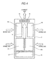
- This fan 15 for exhaust is used to exhaust the air within the disk array box body 2 and cool the interior of the disk array box body 2. Namely, when this fan 15 for exhaust is operated, the air sucked from the front face side and the rear face side of the disk array box body 2 becomes a ventilating wind and also becomes the flow a of a cooling wind within the disk array box body 2 via the interiors of the first disk drive box body 4A and the second disk drive box body 4B and the interiors of the first controller box body 7A and the second controller box body 7B as shown in Fig. 4. This air is then exhausted above the disk array box body 2 and the interior of the disk array box body 2 is effectively cooled by the ventilation of this cooling wind.
- a power source device 16 is arranged in the lowermost portion of the disk array box body 2.
- This power source device 16 supplies a direct current voltage as driving electric power to the plural disk drives 5 of the disk drive section 3, the plural disk adaptor boards 8, the plural channel adapter boards 9, the plural memory boards 10 and the plural switch boards 11 in the disk controller section 6, the processor 13 for management, the computer 14 for output and the fan 15 for exhaust.
- a ventilation interrupting plate 17 for preventing a ventilating wind from flowing from the power source device 16 is arranged in the disk array box body 2 above this power source device 16. Namely, the first controller box body 7a and the second controller box body 7A and the second controller box body 7B are arranged above the power source device 16 through this ventilation interrupting plate 17 in the disk array box body 2. In this way hot air from the power source device is prevented from flowing past the disk array and controller box bodies. Thus, a structure for easily transmitting no heat of the power source device 16 to the sides of the first controller box body 7A and the second controller box body 7B is formed.
- the disk array device 1 of this example has the following advantages by using a dedicated PC for industry in the managing processor 13 for managing the state within the device. Namely, the operating environment temperature of the PC for industry is set to 40° or more and is higher than that of the general PC. Therefore, reliability in the interior of the disk array box body 2 attaining high temperature is improved. Further, reliability relating to the operating time is also improved since the operating time is 5 to 7 years and is longer than that of the general PC. Further, in the disk array device of this example, it is sufficient to operate the notebook type PC 14 only when a maintenance worker sees the state of the disk array device by separating the processor 13 for management and the notebook type PC (computer for output) 14 used in the output of this processor 13.
- the notebook type PC sold at a market can be also used without the problem of the operating time. Further, when the notebook type PC is broken, the notebook type PC can be simply exchanged. Further, since the operating time of the PC for industry is set to a long time such as 5 to 7 years, no frequent maintenance exchange is caused and the influence of a model change can be minimized.
- an arranging structure considering the ventilation property within the disk array box body 2 is adopted in mounting the processor 13 for management and the notebook type PC 14 as a computer for the output of this processor 13.
- the processor 13 (13A, 13B) for management is arranged in a longitudinal arranging state within the disk array box body 2 along the side face of the first disk drive box body 4A by utilizing the space between the first disk drive box body 4A, the second disk drive box body 4B and the disk array box body 2.
- the notebook type PC 14 as a computer for the output of the processor 13 for management is arranged in the longitudinal arranging state along the side face of the second disk drive box body 4B.
- the processor 13 for management is fixed and supported by the disk array box body 2 through an attaching plate 18 in a state in which two processors 13 for management are overlapped.
- the notebook type PC 14 is arranged so as to be pulled out with respect to the disk array box body 2 through a pulling-out mechanism 19.
- This pulling-out mechanism 19 of the notebook type PC performs an operation for pulling the notebook type PC 14 out of the arranging position of the side face of the second disk drive box body 4B and further rotating this notebook type PC 14 on the second disk drive box body 4B side so as to use this notebook type PC 14.
- this pulling-out mechanism 19 is constructed by a pair of upper and lower slide rails 20 horizontally fixed to the disk array box body 2, a frame body 21 fixed to a movable side rail of this slide rail 20, and a pedestal plate 23 rotatably attached to this frame body 21 in the direction perpendicular to the slide direction of the slide rail with a hinge portion 22 as a fulcrum.
- the notebook type PC 14 as a computer for the output of the processor for management is placed and supported in a fixing state on this pedestal plate 23.
- This pulling-out mechanism 19 may be also set to a simple structure in which only one slide rail 20 on the lower side is set and the pedestal plate 23 is rotatably attached to this one slide rail 20.
- the notebook type PC 14 is stored and arranged in the longitudinal arranging state.
- a handle 24 arranged in the front edge portion of the frame body 21 is then gripped from this state and is pulled on this side so that the notebook type PC 14 is pulled out of the disk array box body 2 by the slide of the slide rail 20 as shown in Fig. 6.
- a handle 25 arranged on the rear face side of the pedestal plate 23 is gripped and the pedestal plate 23 is brought down and is rotated until the forward horizontal position of the disk array box body 2 as shown in Fig. 7 so that the notebook type PC 14 is rotated together with the pedestal plate 23 and attains a usable state in front of the disk array box body 2.
- a worker opens the display 14a of the notebook type PC 14 from this state, and turns on the power source of the notebook type PC 14 and makes the display 14a display management information outputted from the processor 13 for management. Further, the disk array device is operated by inputting commands to the processor 13 for management from the keyboard 14b and the mouse section 14c of this notebook type PC 14. After the notebook type PC 14 is used, this notebook type PC 14 is again returned to the storing state of Fig. 5 and is set to the normal longitudinal arranging state.
- the processor 13 for management is arranged in the longitudinal arranging state along the side face of the first disk drive box body 4A.
- the notebook type PC 14 as a computer for output is arranged in the longitudinal arranging state along the side face of the second disk drive box body 4B. Space saving within the disk array box body 2 can be realized by such an arranging construction.
- no processor 13 for management prevents the interval for ventilation between the plural disk drives 5 within the first disk drive box body 4A, and no notebook type PC 14 prevents the interval for ventilation between the plural disk drives 5 within the second disk drive box body 4B (i.e. the notebook PC and processor 13 do not obstruct the intervals for ventilation).
- the processor 13 for management and the notebook type PC 14 do not prevent the intervals for ventilation between the respective boards 8,9,10,11 within the first controller box body 7A and the second controller box body 7B. Accordingly, the processor 13 for management and the notebook type PC 14 do not prevent the flows of a cooling wind passing through the interiors of the first disk drive box body 4A and the second disk drive box body 4B, and a cooling wind passing through the interiors of the first controller box body 7A and the second controller box body 7B. Therefore, the processor 13 for management and the notebook type PC 14 do not have a bad influence on the temperature environment within the disk array device.
- the disk array device 1 of this example is constructed such that the notebook type PC 14 is pulled out of the disk array box body 2 and is further rotated and used as mentioned above. Accordingly, a maintenance worker can make a work while the maintenance worker sees the disk array device on the front face. Further, after the notebook type PC 14 is used, the notebook type PC 14 can be simply stored. Therefore, the maintenance worker can easily make the work and using convenience is good.
- Fig. 9 is a perspective view in which the wiring relating to the processor for management is seen from the front face side in the disk array device of this example.
- Fig. 10 is a perspective view in which this wiring is seen from the rear face side.
- Fig. 11 is a connecting view of this wiring.
- all the connections of a data transmitting-receiving system relating to the processor 13 for management are set to LAN (local area network) connection.
- the two processors 13A, 13B for management are LAN-connected to the notebook type PC 14 as a computer for output through a relay 26 arranged in the lower portion of the disk array box body 2.
- the two processors 13A, 13B for management and the relay 26 are respectively connected by LAN cables 40, 41.
- the relay 26 and the notebook type PC 14 are connected by a LAN cable 42.
- the two processors 13A, 13B for management are respectively connected to the switch board 11 of the disk controller section by LAN cables 43, 44. Further, the two processors 13A, 13B formanagement are connected to each other by a LAN cable 45.
- the two processors 13A, 13B for management are respectively connected to an output board 27 of the power source device 16 by power cables 46, 47 as power source system connection.
- the notebook type PC 14 is connected to a breaker box 28 for PC arranged in the power source device 16 by a power cable 48.
- LAN cables 40, 41, 42, 43, 44 and power cables 46, 47, 48 are wired along the external surfaces of the first controller box body 7A and the second controller box body 7B so as not to prevent (obstruct) the flows of the cooling winds passing through the interiors of the first controller box body 7A and the second controller box body 7B. Further, the LAN cables 40, 41, 42, 43, 44 and the power cables 46, 47, 48 are wired as convergently as possible so as to minimize the influence on the cooling wind passing through the interior of the disk array box body 2.
- the relay 26 and the output board 27 of the power source device are arranged on the side opposed to the processor 13 for management within the disk array box body 2.
- the processor 13 for management is arranged on the upper left-hand side seen from the front face side within the disk array box body 2.
- the relay 26 and the output board 27 of the power source device are arranged on the lower right-hand side.
- the LAN cables 40, 41, 42, 43, 44 and the power cables 46, 47, 48 can be dispersively wired on both sides without being concentrated onto one side of the disk array box body 2 so that the influence on the cooling wind passing through the interior of the disk array box body 2 can be minimized.
- the relay 26 and the output board 27 of the power source device may be also arranged on the same side as the processor 13 for management.
- the lengths of the LAN cables 40, 41, 42, 43, 44 and the power cables 46, 47, 48 can be shortened, there is an advantage in that complicatedness of the wiring can be reduced.
- the relay 26 and the output board 27 of the power source device are arranged in proximity to each other, it is possible to efficiently make the connecting work of this relay 26, the LAN cables 40, 41, 42 with respect to the output board 27, and the power cables 46, 47.
- the relay 26 since the relay 26 is arranged in the position proximate to the output board 27 of the power source device 16 arranged in the lowermost portion of the disk array box body 2, no relay 26 prevents the cooling wind flowed into the disk array box body 2 between the processor 13 for management and the notebook type PC 14 arranged on the side opposed to this relay 26.
- the relay 26 may be also arranged in a position separated from the output board 27 of the power source device 16. In this case, for example, no relay 26 prevents the cooling wind flowed into the disk array box body 2 by arranging the relay 26 on the side faces of the controller box bodies 7A, 7B or the side faces of the disk drive box bodies 4A, 4B.
- the processor 13 for management and the notebook type PC 14 are connected via the LAN, the connection from the exterior can be easily realized.
- the processor 13 for management is connected to plural external LANs through hubs 29, 30 for an external LAN in the exterior of the disk array device, and can output and manage management information of the disk array device in an output terminal at an external strongpoint. Further, the management information of the disk array device can be also notified to the external strongpoint through a telephone line (ISDN line) 31 by building a modem into the processor for management.
- ISDN line telephone line
- the LAN cable is used in the LAN connection relating to the processor 13 for management, but this LAN connection may be also constructed by wireless LAN.
- this LAN connection since the wiring within the disk array box body 2 can be further omitted, complicatedness of the wiring can be greatly dissolved.
- the notebook type PC 14 is connected to the processor 13 for management at all times, but can be also constructed so as to be detachably attached to the processor 13 for management.
- the notebook type PC 14 is normally detached and a worker connects the notebook type PC 14 to the processor 13 for management by the LAN only at the maintenance working time.
- Fig. 12 is a perspective view showing a disk array device of the second embodiment of the present invention.
- the disk array device 1 shown in this example is constructed by arranging two disk array box bodies, i.e., a first disk array box body 2A and a second disk array box body 2B.
- the first disk array box body 2A and the second disk array box body 2B are opened on the front face side, and front doors 32A and 32B for opening and closing these opening faces are attached.
- Each of these front doors 32A and 32B is a door of a rotary type symmetrically opened leftward and rightward.
- the first disk array box body 2A has a disk controller section 6 and the second disk array box body 2B has a disk unit section 3.
- the disk controller section 6 of the first disk array box body 2A is constructed by spacing and arranging a disk adapter board 8, a channel adapter board 9, a memory board 10 and a switch board 11 in the plural at intervals for ventilation within a controller box body 7.
- the disk unit section 3 of the second disk array box body 2B is constructed by spacing plural disk drives 5 at intervals for ventilation and arranging the plural disk drives 5 in a matrix shape within a disk drive box body 4.
- the number of second disk array box bodies 2B having this disk unit section 3 can be increased to a plural number.
- the disk drive box body 4 is opened on its front and rear faces, and ventilation holes are formed everywhere in upper and lower plate portions and an intermediate partition plate portion.
- the controller box body 7 is also opened on its front and rear faces, and ventilation holes are formed everywhere in upper and lower plate portions.
- a structure of preferable ventilation property is formed in each of the disk drive box body 4 and the controller box body 7.
- the power source device 16 (a main power source device 16A and a battery 16B for an auxiliary) is arranged in the lower portion of the first disk array box body 2A.
- the controller box body 7 is arranged above this power source device 16, and plural fans 15 for exhaust are arranged on the upper face of the first disk array box body 2A above this controller box body 7.
- plural fans 33 for intake gas are arranged in the first disk array box body 2A so as to cover the forward portion of the power source device 16.
- Many ventilation holes 34 are arranged in the front door 32A correspondingly to this fan 33 for intake gas.
- the air sucked from the front face side by the fan 33 for intake gas becomes the flow a of a cooling wind via the power source device 16 and passes through the interior of the controller box body 7. Thereafter, the air is exhausted above the first disk array box body 2A by the fan 15 for exhaust and the interior of the first disk array box body 2A is effectively cooled by the ventilation of this cooling wind.
- plural fans 33 for intake gas are arranged in the lowermost portion of the second disk array box body 2B, and the disk drive box body 4 is arranged above this fan 33 for intake gas.
- plural fans 15 for exhaust are arranged on the upper face of the second disk array box body 2B above this disk drive box body 4.
- Many ventilation holes 34 are arranged in the front door 32B correspondingly to the fan 33 for intake gas arranged in this second disk array box body 2B.
- the air sucked from the front face side by the fan 33 for intake gas becomes the flow of a cooling wind and passes through the interior of the disk drive box body 4. Thereafter, the air is exhausted above the second disk array box body 2B by the fan 15 for exhaust, and the interior of the second disk array box body 2B is effectively cooled by the ventilation of this cooling wind.
- the processor 13 for management is mounted by utilizing the space located between the controller box body 7, the power source device 16 and the first disk array box body 2A within the first disk array box body 2A.
- the processor 13 for management is arranged in a longitudinal arranging state in which the two processors 13A, 13B for management are vertically arranged along the side faces of the controller box body 7 and the power source device 16.
- the notebook type PC 14 as a computer for output in the processor 13 for management is mounted to the front door 32A of the first disk array box body 2A.
- the notebook type PC 14 is placed and fixed onto a pedestal plate 35 rotatably attached to the rear face side of the front door 32A.
- the pedestal plate 35 is rotated in the vertical direction with a support shaft 36 as a center.
- the notebook type PC 14 is stored and arranged in the longitudinal arranging state along the rear face side of the front door 32A in a state in which this pedestal plate 35 is perpendicular.
- the notebook type PC 14 is normally stored in the longitudinal arranging state on the rear face side of the front door 32A in the closing state of the front door 32A.
- the notebook type PC 14 is set to a usable state by horizontally bringing-down and rotating the pedestal plate 35 in the opening state of the front door 32A.
- the disk array device of this example is constructed such that the processor 13 for management is arranged in the longitudinal arranging state along the side faces of the controller box body 7 and the power source device 16 in the first disk array box body 2A. Accordingly, no processor 13 for management prevents the intervals for ventilation between the disk adapter board 8, the channel adapter board 9, the memory board 10 and the switch board 11 within the controller box body 7 , and also prevents the ventilation near the power source device 16. Further, the notebook type PC 14 as a computer for output is arranged on the rear face side of the front door 32A so as to attain the storing state of the longitudinal arrangement.
- no notebook type PC 14 prevents the intervals for ventilation between the disk adapter board 8 , the channel adapter board 9, the memory board 10 and the switch board 11 within the controller box body 7, and also prevents the ventilation near the power source device 16.
- the processor 13 for management and the notebook type PC 14 do not prevent the flow of the cooling wind passing through the interior of the first disk array box body 2A, the processor 13 for management and the notebook type PC 14 have no bad influence on the temperature environment within the disk array device.
- the wiring of a peripheral portion of the processor 13 for management in the disk array device of this example is similar to that in the above first embodiment.
- the processor 13 for management and the notebook type PC 14 are connected by LAN having simple wiring. Therefore, the notebook type PC 14 can be easily arranged even in a position separated from the processor 13 for management.
- the notebook type PC 14 can be also arranged in the front door 32B of the second disk array box body 2B side.
- Fig. 15 shows another arrangement example of the processor for management.
- the processor 13 for management is arranged in a transversal arranging state in the central portion within the first disk array box body 2A.
- the processor 13 for management is arranged in the vertical overlapping state of the two processors 13A, 13B for management in the space between the power source device 16 and the controller box body 7.
- the processor 13 for management is arranged in the forward portion dislocated from the central portion of the flow of a cooling wind so as not to prevent the flow a of the cooling wind within the first disk array box body 2A.
- Fig. 17 shows still another arrangement example of the processor for management.
- the processor 13 for management is arranged in the transversal arranging state in the lowermost portion within the first disk array box body 2A. As shown in Fig. 18, the processor 13 for management is here arranged in the vertical overlapping state of the two processors 13A, 13B for management in the space of the lower side of the power source device 16. In this case, since no processor 13 for management prevents the flow a of a cooling wind within the first disk array box body 2A, this arrangement is most effective.
Applications Claiming Priority (2)
| Application Number | Priority Date | Filing Date | Title |
|---|---|---|---|
| JP2003400302 | 2003-11-28 | ||
| JP2003400302A JP4274916B2 (ja) | 2003-11-28 | 2003-11-28 | ディスクアレイ装置 |
Publications (2)
| Publication Number | Publication Date |
|---|---|
| EP1538628A1 true EP1538628A1 (de) | 2005-06-08 |
| EP1538628B1 EP1538628B1 (de) | 2010-03-17 |
Family
ID=34463900
Family Applications (1)
| Application Number | Title | Priority Date | Filing Date |
|---|---|---|---|
| EP04255181A Expired - Fee Related EP1538628B1 (de) | 2003-11-28 | 2004-08-27 | Aufstellungseinrichtung für Festplatten |
Country Status (5)
| Country | Link |
|---|---|
| US (2) | US7016191B2 (de) |
| EP (1) | EP1538628B1 (de) |
| JP (1) | JP4274916B2 (de) |
| CN (1) | CN100426415C (de) |
| DE (1) | DE602004026023D1 (de) |
Families Citing this family (44)
| Publication number | Priority date | Publication date | Assignee | Title |
|---|---|---|---|---|
| US7153772B2 (en) * | 2003-06-12 | 2006-12-26 | Asm International N.V. | Methods of forming silicide films in semiconductor devices |
| JP2005316861A (ja) | 2004-04-30 | 2005-11-10 | Hitachi Ltd | ディスクアレイ装置 |
| JP4628929B2 (ja) * | 2004-11-30 | 2011-02-09 | 富士通コンポーネント株式会社 | ラックマウントシステム |
| US7345886B2 (en) * | 2005-04-01 | 2008-03-18 | Hewlett-Packard Development Company, L.P. | Electronic device enclosure with sliding and pivoting doors |
| JP4818700B2 (ja) * | 2005-12-02 | 2011-11-16 | 株式会社日立製作所 | 記憶制御装置 |
| WO2007084403A2 (en) * | 2006-01-13 | 2007-07-26 | Sun Microsystems, Inc. | Compact rackmount storage server |
| US7441079B2 (en) | 2006-03-21 | 2008-10-21 | International Business Machines Corporation | Data location management in high density packaging |
| US7564692B2 (en) * | 2006-10-05 | 2009-07-21 | William Tse Lin Hsiung | Retaining structure for mounting two independent computers within one standard slot in a computer cabinet |
| US20080123284A1 (en) * | 2006-11-29 | 2008-05-29 | Dell Products, Lp | Server rack door mounted display assembly |
| JP2008217241A (ja) * | 2007-03-01 | 2008-09-18 | Fujitsu Component Ltd | ラック管理システム、表示装置および制御装置 |
| US8367548B2 (en) * | 2007-03-16 | 2013-02-05 | Asm America, Inc. | Stable silicide films and methods for making the same |
| US20090154091A1 (en) | 2007-12-17 | 2009-06-18 | Yatskov Alexander I | Cooling systems and heat exchangers for cooling computer components |
| US8170724B2 (en) | 2008-02-11 | 2012-05-01 | Cray Inc. | Systems and associated methods for controllably cooling computer components |
| CN101516166B (zh) * | 2008-02-22 | 2010-12-08 | 华为技术有限公司 | 一种横插框及通信机柜 |
| US7898799B2 (en) * | 2008-04-01 | 2011-03-01 | Cray Inc. | Airflow management apparatus for computer cabinets and associated methods |
| JP2009288878A (ja) * | 2008-05-27 | 2009-12-10 | Hitachi Ltd | ストレージ装置、及びストレージ装置の冷却方法 |
| JP2010039826A (ja) * | 2008-08-06 | 2010-02-18 | Hitachi Ltd | ストレージ装置、ファン装置、及びコントローラユニット装置 |
| JP4950968B2 (ja) * | 2008-09-01 | 2012-06-13 | 株式会社日立製作所 | ストレージ装置 |
| US7903403B2 (en) * | 2008-10-17 | 2011-03-08 | Cray Inc. | Airflow intake systems and associated methods for use with computer cabinets |
| US8081459B2 (en) | 2008-10-17 | 2011-12-20 | Cray Inc. | Air conditioning systems for computer systems and associated methods |
| JP4760957B2 (ja) * | 2009-05-21 | 2011-08-31 | ダイキン工業株式会社 | 空気調和装置 |
| JP4826654B2 (ja) * | 2009-05-21 | 2011-11-30 | ダイキン工業株式会社 | 空気調和装置 |
| TWI426860B (zh) * | 2009-11-20 | 2014-02-11 | Delta Electronics Inc | 熱交換裝置及應用熱交換裝置的密閉式電器設備 |
| TW201121395A (en) * | 2009-12-03 | 2011-06-16 | Hon Hai Prec Ind Co Ltd | Server heat dissipation device and fan module thereof |
| US20110176270A1 (en) * | 2010-01-19 | 2011-07-21 | Ku-Yang Chou | System rack for accessing hard disks in dual directions |
| US8472181B2 (en) | 2010-04-20 | 2013-06-25 | Cray Inc. | Computer cabinets having progressive air velocity cooling systems and associated methods of manufacture and use |
| CN102289268A (zh) * | 2010-06-17 | 2011-12-21 | 英业达股份有限公司 | 机架伺服器 |
| US8335081B2 (en) | 2010-07-16 | 2012-12-18 | Rockwell Automation Technologies, Inc. | Heat sink cooling arrangement for multiple power electronic circuits |
| US8325478B2 (en) * | 2010-07-16 | 2012-12-04 | Rockwell Automation Technologies, Inc. | Cooling duct attachment and sealing for a motor drive |
| US8325479B2 (en) * | 2010-07-16 | 2012-12-04 | Rockwell Automation Technologies, Inc. | Motor drive cooling duct system and method |
| US20130120922A1 (en) * | 2011-11-14 | 2013-05-16 | Chassis Plans, LLC | Side access lcd keyboard console with kvm |
| US8925739B2 (en) * | 2012-07-26 | 2015-01-06 | Lenovo Enterprise Solutions (Singapore) Pte. Ltd. | High-capacity computer rack with rear-accessible side bays |
| JP2014183175A (ja) * | 2013-03-19 | 2014-09-29 | Toshiba Corp | 放熱器 |
| US9047045B2 (en) * | 2013-03-27 | 2015-06-02 | International Business Machines Corporation | Multi-directional display console for an electronic equipment cabinet |
| US9894015B2 (en) | 2013-09-06 | 2018-02-13 | Alaxala Networks Corporation | Communication apparatus and communication system |
| US20150272327A1 (en) * | 2014-03-31 | 2015-10-01 | Josef Rabinovitz | Pro Bracket for mounting a Mac Pro computer |
| US9629279B2 (en) * | 2015-02-03 | 2017-04-18 | International Business Machines Corporation | Low-profile swing gate to support service element interface hardware |
| US9883605B2 (en) * | 2015-04-29 | 2018-01-30 | Dell Products L.P. | Rack attic device coupling system |
| US10334746B2 (en) * | 2015-05-05 | 2019-06-25 | Facebook, Inc. | Component mounting assembly |
| CN104968172A (zh) * | 2015-07-28 | 2015-10-07 | 苏州市龙源电力科技股份有限公司 | 一种具有折叠面板的电气控制柜 |
| US9861004B2 (en) | 2015-12-03 | 2018-01-02 | International Business Machines Corporation | Zero-U rack keyboard and monitor |
| US10827643B2 (en) | 2018-09-21 | 2020-11-03 | International Business Machines Corporation | Rack having a stowable retractable terminal for varying the positioning of input devices relative to the rest of the rack and/or a user |
| US11533826B2 (en) * | 2020-06-11 | 2022-12-20 | Baidu Usa Llc | Air cooling system for component high dense clusters |
| CN111721443A (zh) * | 2020-06-30 | 2020-09-29 | 吉林建筑大学 | 一种可实现温度检测报警的分离式阵列计算机 |
Citations (6)
| Publication number | Priority date | Publication date | Assignee | Title |
|---|---|---|---|---|
| EP0635836A1 (de) * | 1993-07-22 | 1995-01-25 | Hitachi, Ltd. | Magnetisches Plattenspeichergerät |
| EP0776009A2 (de) * | 1990-11-30 | 1997-05-28 | Fujitsu Limited | Plattenspeicherungseinheit mit einer Mehrzahl von Plattenmodulen |
| US6021047A (en) * | 1997-10-24 | 2000-02-01 | Dell U.S.A., L,P. | Computer and a rack mount system and method for a computer |
| US6353532B1 (en) * | 1999-09-03 | 2002-03-05 | Compaq Information Technologies Group, L.P. | Pivotable monitor mounting |
| US6442030B1 (en) * | 2001-04-26 | 2002-08-27 | Central Industrial Supply Company, Inc. | Server system rack drawer with keyboard, flat panel display and electronic switch |
| US6621692B1 (en) * | 2001-08-30 | 2003-09-16 | Emc Corporation | Computerized system having an interface apparatus with improved mounting features |
Family Cites Families (14)
| Publication number | Priority date | Publication date | Assignee | Title |
|---|---|---|---|---|
| US5173819A (en) | 1988-10-05 | 1992-12-22 | Hitachi, Ltd. | Disk apparatus having an improved cooling structure |
| US5414591A (en) | 1991-04-15 | 1995-05-09 | Hitachi, Ltd. | Magnetic disk storage system |
| US5388032A (en) * | 1993-05-04 | 1995-02-07 | Ibus Technologies, Inc. | Computer equipment monitor and discriminator |
| JP3264465B2 (ja) | 1993-06-30 | 2002-03-11 | 株式会社日立製作所 | 記憶システム |
| JPH07261874A (ja) * | 1994-03-18 | 1995-10-13 | Toshiba Corp | 情報処理装置 |
| DE19609651C2 (de) * | 1996-03-13 | 1998-01-22 | Loh Kg Rittal Werk | Schaltschrank-Klimatisierungseinrichtung |
| US6742068B2 (en) | 1997-06-30 | 2004-05-25 | Emc Corporation | Data server with hot replaceable processing unit modules |
| US6175490B1 (en) * | 1997-10-01 | 2001-01-16 | Micron Electronics, Inc. | Fault tolerant computer system |
| US6061966A (en) * | 1998-06-30 | 2000-05-16 | Emc Corporation | Electrical cabinet having a door stop |
| US6039414A (en) * | 1998-12-11 | 2000-03-21 | Alcatel Usa Sourcing, L.P. | Modular electronic enclosure having rotational molded plastic interlocking components |
| US6129434A (en) * | 1998-12-11 | 2000-10-10 | Alcatel Usa Sourcing, L.P. | Support structure for an electronic enclosure |
| US6510050B1 (en) * | 2000-11-21 | 2003-01-21 | Sun Microsystems, Inc. | High density packaging for multi-disk systems |
| US6583989B1 (en) | 2000-12-22 | 2003-06-24 | Emc Corporation | Computer system |
| US6904968B2 (en) | 2001-09-14 | 2005-06-14 | Hewlett-Packard Development Company, L.P. | Method and apparatus for individually cooling components of electronic systems |
-
2003
- 2003-11-28 JP JP2003400302A patent/JP4274916B2/ja not_active Expired - Fee Related
-
2004
- 2004-02-10 US US10/774,591 patent/US7016191B2/en not_active Expired - Fee Related
- 2004-08-27 EP EP04255181A patent/EP1538628B1/de not_active Expired - Fee Related
- 2004-08-27 CN CNB2004100572863A patent/CN100426415C/zh not_active Expired - Fee Related
- 2004-08-27 DE DE602004026023T patent/DE602004026023D1/de active Active
-
2005
- 2005-11-02 US US11/264,008 patent/US7057892B2/en not_active Expired - Fee Related
Patent Citations (6)
| Publication number | Priority date | Publication date | Assignee | Title |
|---|---|---|---|---|
| EP0776009A2 (de) * | 1990-11-30 | 1997-05-28 | Fujitsu Limited | Plattenspeicherungseinheit mit einer Mehrzahl von Plattenmodulen |
| EP0635836A1 (de) * | 1993-07-22 | 1995-01-25 | Hitachi, Ltd. | Magnetisches Plattenspeichergerät |
| US6021047A (en) * | 1997-10-24 | 2000-02-01 | Dell U.S.A., L,P. | Computer and a rack mount system and method for a computer |
| US6353532B1 (en) * | 1999-09-03 | 2002-03-05 | Compaq Information Technologies Group, L.P. | Pivotable monitor mounting |
| US6442030B1 (en) * | 2001-04-26 | 2002-08-27 | Central Industrial Supply Company, Inc. | Server system rack drawer with keyboard, flat panel display and electronic switch |
| US6621692B1 (en) * | 2001-08-30 | 2003-09-16 | Emc Corporation | Computerized system having an interface apparatus with improved mounting features |
Also Published As
| Publication number | Publication date |
|---|---|
| US20050117310A1 (en) | 2005-06-02 |
| DE602004026023D1 (de) | 2010-04-29 |
| JP2005166100A (ja) | 2005-06-23 |
| US7057892B2 (en) | 2006-06-06 |
| CN100426415C (zh) | 2008-10-15 |
| EP1538628B1 (de) | 2010-03-17 |
| JP4274916B2 (ja) | 2009-06-10 |
| US20060056148A1 (en) | 2006-03-16 |
| US7016191B2 (en) | 2006-03-21 |
| CN1622217A (zh) | 2005-06-01 |
Similar Documents
| Publication | Publication Date | Title |
|---|---|---|
| US7016191B2 (en) | Disk array device | |
| EP1975940B1 (de) | Speicherplattensystem | |
| JP5047993B2 (ja) | 排気ユニット | |
| JP4312424B2 (ja) | ディスクアレイ装置 | |
| US7242580B1 (en) | Disk array apparatus | |
| US7769489B2 (en) | Robot control device and robot system | |
| US20040160720A1 (en) | Data storage system | |
| EP1709855A2 (de) | Selbstkühlungs-gehäuse für elektronische geräte mit ausfalltoerantem kühlsystem und betriebsverfahren | |
| EP3849293B1 (de) | Geschlossenes kaltpoolsystem | |
| JP2006300433A (ja) | 空気調和装置 | |
| JP4557743B2 (ja) | 制御装置 | |
| WO2020163939A1 (en) | Transportable datacenter | |
| JP2004286365A (ja) | 電子機器収容用ラック、空気調和システム、これに用いる制御ボックス及び空気調和システムの制御方法 | |
| JPH11225835A (ja) | 移動式サーバーラック | |
| JP2013145094A (ja) | 空気調和機の室外機 | |
| CN220292325U (zh) | 一种用于楼宇自控的智能控制柜 | |
| CN112460783B (zh) | 列间空调器 | |
| JP2018189263A (ja) | 空気調和機の室外機 | |
| CN212305497U (zh) | 一种用于通用管理介质的安全管理装置 | |
| JP7248393B2 (ja) | 通信機器用ラック | |
| JP3104190U (ja) | 無線機器収容局舎 | |
| CN103853274A (zh) | 服务器机柜 | |
| JP2022041571A (ja) | 空気調和機の室外機 | |
| JP2022041569A (ja) | 空気調和機の室外機 | |
| WO2008007417A1 (fr) | Rack d'armoire pour appareils électroniques |
Legal Events
| Date | Code | Title | Description |
|---|---|---|---|
| PUAI | Public reference made under article 153(3) epc to a published international application that has entered the european phase |
Free format text: ORIGINAL CODE: 0009012 |
|
| 17P | Request for examination filed |
Effective date: 20040920 |
|
| AK | Designated contracting states |
Kind code of ref document: A1 Designated state(s): AT BE BG CH CY CZ DE DK EE ES FI FR GB GR HU IE IT LI LU MC NL PL PT RO SE SI SK TR |
|
| AX | Request for extension of the european patent |
Extension state: AL HR LT LV MK |
|
| AKX | Designation fees paid |
Designated state(s): DE FR GB |
|
| 17Q | First examination report despatched |
Effective date: 20051213 |
|
| GRAP | Despatch of communication of intention to grant a patent |
Free format text: ORIGINAL CODE: EPIDOSNIGR1 |
|
| GRAS | Grant fee paid |
Free format text: ORIGINAL CODE: EPIDOSNIGR3 |
|
| GRAA | (expected) grant |
Free format text: ORIGINAL CODE: 0009210 |
|
| AK | Designated contracting states |
Kind code of ref document: B1 Designated state(s): DE FR GB |
|
| REG | Reference to a national code |
Ref country code: GB Ref legal event code: FG4D |
|
| REF | Corresponds to: |
Ref document number: 602004026023 Country of ref document: DE Date of ref document: 20100429 Kind code of ref document: P |
|
| PLBE | No opposition filed within time limit |
Free format text: ORIGINAL CODE: 0009261 |
|
| STAA | Information on the status of an ep patent application or granted ep patent |
Free format text: STATUS: NO OPPOSITION FILED WITHIN TIME LIMIT |
|
| 26N | No opposition filed |
Effective date: 20101220 |
|
| REG | Reference to a national code |
Ref country code: FR Ref legal event code: ST Effective date: 20110502 |
|
| PG25 | Lapsed in a contracting state [announced via postgrant information from national office to epo] |
Ref country code: FR Free format text: LAPSE BECAUSE OF NON-PAYMENT OF DUE FEES Effective date: 20100831 |
|
| PGFP | Annual fee paid to national office [announced via postgrant information from national office to epo] |
Ref country code: GB Payment date: 20120822 Year of fee payment: 9 |
|
| PGFP | Annual fee paid to national office [announced via postgrant information from national office to epo] |
Ref country code: DE Payment date: 20120822 Year of fee payment: 9 |
|
| GBPC | Gb: european patent ceased through non-payment of renewal fee |
Effective date: 20130827 |
|
| PG25 | Lapsed in a contracting state [announced via postgrant information from national office to epo] |
Ref country code: DE Free format text: LAPSE BECAUSE OF NON-PAYMENT OF DUE FEES Effective date: 20140301 |
|
| REG | Reference to a national code |
Ref country code: DE Ref legal event code: R119 Ref document number: 602004026023 Country of ref document: DE Effective date: 20140301 |
|
| PG25 | Lapsed in a contracting state [announced via postgrant information from national office to epo] |
Ref country code: GB Free format text: LAPSE BECAUSE OF NON-PAYMENT OF DUE FEES Effective date: 20130827 |