EP1538489B1 - Entwicklungsgerät mit einer zweiten Tonerzuführeinheit - Google Patents
Entwicklungsgerät mit einer zweiten Tonerzuführeinheit Download PDFInfo
- Publication number
- EP1538489B1 EP1538489B1 EP04028596.7A EP04028596A EP1538489B1 EP 1538489 B1 EP1538489 B1 EP 1538489B1 EP 04028596 A EP04028596 A EP 04028596A EP 1538489 B1 EP1538489 B1 EP 1538489B1
- Authority
- EP
- European Patent Office
- Prior art keywords
- developer
- toner
- supplying member
- supplying
- roller
- Prior art date
- Legal status (The legal status is an assumption and is not a legal conclusion. Google has not performed a legal analysis and makes no representation as to the accuracy of the status listed.)
- Expired - Lifetime
Links
- 239000000463 material Substances 0.000 claims description 3
- 238000013459 approach Methods 0.000 claims description 2
- 238000012546 transfer Methods 0.000 description 18
- 239000002245 particle Substances 0.000 description 15
- 238000004140 cleaning Methods 0.000 description 9
- 229920000122 acrylonitrile butadiene styrene Polymers 0.000 description 3
- 238000005054 agglomeration Methods 0.000 description 3
- 230000002776 aggregation Effects 0.000 description 3
- 230000007423 decrease Effects 0.000 description 3
- 230000005484 gravity Effects 0.000 description 3
- 230000003252 repetitive effect Effects 0.000 description 3
- 239000011800 void material Substances 0.000 description 3
- 229920006311 Urethane elastomer Polymers 0.000 description 2
- 230000001771 impaired effect Effects 0.000 description 2
- 238000012986 modification Methods 0.000 description 2
- 230000004048 modification Effects 0.000 description 2
- 230000001105 regulatory effect Effects 0.000 description 2
- 239000012858 resilient material Substances 0.000 description 2
- 229920002379 silicone rubber Polymers 0.000 description 2
- 239000004945 silicone rubber Substances 0.000 description 2
- 239000007787 solid Substances 0.000 description 2
- 238000012360 testing method Methods 0.000 description 2
- 238000005411 Van der Waals force Methods 0.000 description 1
- 230000015572 biosynthetic process Effects 0.000 description 1
- 239000003086 colorant Substances 0.000 description 1
- 239000002131 composite material Substances 0.000 description 1
- 230000007547 defect Effects 0.000 description 1
- 230000001419 dependent effect Effects 0.000 description 1
- 238000011161 development Methods 0.000 description 1
- 238000004519 manufacturing process Methods 0.000 description 1
- 239000007769 metal material Substances 0.000 description 1
- 238000011144 upstream manufacturing Methods 0.000 description 1
Images



Classifications
-
- G—PHYSICS
- G03—PHOTOGRAPHY; CINEMATOGRAPHY; ANALOGOUS TECHNIQUES USING WAVES OTHER THAN OPTICAL WAVES; ELECTROGRAPHY; HOLOGRAPHY
- G03G—ELECTROGRAPHY; ELECTROPHOTOGRAPHY; MAGNETOGRAPHY
- G03G15/00—Apparatus for electrographic processes using a charge pattern
- G03G15/06—Apparatus for electrographic processes using a charge pattern for developing
- G03G15/08—Apparatus for electrographic processes using a charge pattern for developing using a solid developer, e.g. powder developer
- G03G15/0806—Apparatus for electrographic processes using a charge pattern for developing using a solid developer, e.g. powder developer on a donor element, e.g. belt, roller
- G03G15/0808—Apparatus for electrographic processes using a charge pattern for developing using a solid developer, e.g. powder developer on a donor element, e.g. belt, roller characterised by the developer supplying means, e.g. structure of developer supply roller
-
- G—PHYSICS
- G03—PHOTOGRAPHY; CINEMATOGRAPHY; ANALOGOUS TECHNIQUES USING WAVES OTHER THAN OPTICAL WAVES; ELECTROGRAPHY; HOLOGRAPHY
- G03G—ELECTROGRAPHY; ELECTROPHOTOGRAPHY; MAGNETOGRAPHY
- G03G2215/00—Apparatus for electrophotographic processes
- G03G2215/06—Developing structures, details
- G03G2215/0602—Developer
- G03G2215/0604—Developer solid type
- G03G2215/0614—Developer solid type one-component
-
- G—PHYSICS
- G03—PHOTOGRAPHY; CINEMATOGRAPHY; ANALOGOUS TECHNIQUES USING WAVES OTHER THAN OPTICAL WAVES; ELECTROGRAPHY; HOLOGRAPHY
- G03G—ELECTROGRAPHY; ELECTROPHOTOGRAPHY; MAGNETOGRAPHY
- G03G2215/00—Apparatus for electrophotographic processes
- G03G2215/08—Details of powder developing device not concerning the development directly
- G03G2215/0802—Arrangements for agitating or circulating developer material
- G03G2215/085—Stirring member in developer container
- G03G2215/0852—Stirring member in developer container reciprocating
Definitions
- the present invention relates to a developer and an image-forming apparatus.
- Conventional electrophotographic image-forming apparatus include a printer, a copying machine, a facsimile machine, and a composite apparatus of these.
- a photoconductive drum is surrounded by a charging roller, an exposing unit, a developing unit, a transfer roller, and a cleaning roller.
- the developing unit includes primarily a developing roller and a toner-supplying roller.
- the charging roller charges the surface of a photoconductive drum uniformly.
- the exposing unit illuminates the charged surface of the photoconductive drum to form an electrostatic latent image.
- the developing unit applies toner to an electrostatic latent image formed on the photoconductive drum to develop the electrostatic latent image into a toner image.
- the toner image is then transferred onto a print medium by the transfer roller. Then, the print medium is advanced to a fixing unit where the toner image on the print medium is fused into a permanent image.
- an image drum unit includes a photoconductive drum, a charging roller, a developing roller, and a toner-supplying roller assembled integrally, so that when the toner is exhausted or the photoconductive drum, charging roller, developing roller, and toner-supplying roller wear out, the entire ID unit can be replaced with a new, unused one.
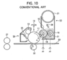
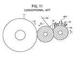
- FIG. 10 is a schematic view of a conventional printer and Fig. 11 illustrates the operation of a conventional developing. apparatus.
- an ID cartridge 10 includes a photoconductive drum 11 that rotates in a direction shown by arrow A.
- a charging roller 12 charges the entire surface of the photoconductive drum 11 uniformly.
- An exposing unit illuminates the charged surface of the photoconductive drum 11 to form an electrostatic latent image.
- a developing roller 14 rotates in contact with the photoconductive drum 11 in a direction shown by arrow B and supplies the toner to the electrostatic latent image to develop the electrostatic latent image into a toner image.
- a developing blade 15 restricts the thickness of a layer of toner 31 formed on the developing roller 14, thereby setting an amount of toner 31 that is transferred from the developing roller 14 to the photoconductive drum 11.
- a toner-supplying roller 16 rotates in contact with the developing roller 14 in a direction shown by arrow C and supplies the toner 31 received from the a toner cartridge 21 to the developing roller 14.
- An agitator 28 agitates the toner 31.
- the developing roller 14, developing blade 15, toner-supplying roller 16, and agitator 28 form a developing unit.
- a transfer roller 22 opposes the photoconductive drum 11 to define a transfer point between the transfer roller 22 and photoconductive drum 11.
- the transfer roller 22 rotates in a direction shown by arrow D and transfers the toner image formed on the photoconductive drum 11 onto paper 23 that passes through the transfer point.
- a cleaning unit 24 removes residual toner on the photoconductive drum 11 after transferring the toner image onto the paper 23.
- the cleaning unit 24 includes a cleaning blade 25 that is in contact with the surface of the photoconductive drum 11.
- the photoconductive drum 11, charging roller 12, developing unit, toner cartridge 21, and cleaning unit 24 form an ID cartridge 10.
- a fixing unit 27 is located downstream of the transfer point with respect to the transport path of the paper 23 and fixes the toner image transferred onto the paper 23.
- the developing unit will be described.
- the aforementioned developing unit is of the single-component developer type.
- the toner 31 is a single-component developer.
- the toner cartridge 21 has an opening that can be opened and closed. When the opening is opened, a predetermined amount of toner 31 falls from the toner cartridge 21 through the opening into the developing unit.
- the toner 31 is agitated by the agitator 28 and is supplied to the toner-supplying roller 16.
- the toner-supplying roller 16 and the developing roller 14 rotate in contact with each other in the same direction but at different speeds.
- the potential difference between the toner-supplying roller 16 and the developing roller 14 causes the toner 31 to move from the toner-supplying roller 16 to the developing roller 14.
- the toner-supplying roller 16 also functions to remove excess toner from the circumferential surface of the developing roller 14.
- the toner-supplying roller 16 is formed of a foamed resilient material such as silicone rubber and urethane rubber, and has a plurality of cells in the shape of a recess in the circumferential surface.
- the friction occurs due to the difference in rotational speed and rotational direction at a nip formed between the toner-supplying roller 16 and the developing roller 14, and causes the toner 31 to be lightly charged.
- the toner 31 on the developing roller 14 is transferred to the developingblade 15 which in turn restricts the thickness of the layer of toner on the developing roller 14. Then, the toner 31 is delivered to a development point where the developing roller 14 contacts the photoconductive drum 11. The toner 31 is attracted to the photoconductive drum 11 by the Coulomb force, thereby developing the electrostatic latent image on the photoconductive drum 11 into a toner image.
- the cells scrape the toner 31 that surround the toner-supplying roller 31, and supplies the toner 31 to the developing roller 14.
- the toner 31 passes the nip formed between the developing roller 14 and the toner-supplying roller 16, the toner is subjected to mechanical stress and heat generated during printing. As a result, the toner loses its fluidity and becomes packed near the toner-supplying roller 16 after repetitive printing cycles over time.
- the toner cartridge 21 when the toner cartridge 21 is disposed above the toner-supplying roller 16, the toner in a region AR immediately over the toner-supplying roller 16 falls by gravity onto the toner-supplying roller 16. This exerts a mechanical stress on the toner 31 and causes the toner to agglomerate.
- the ability of the cells to scrape the toner particles reduces, supplying less toner 31 to the developing roller 14. Especially, toner agglomeration tends to occur in the region AR1 and less toner falls onto the toner-supplying roller so that less toner is supplied to the developing roller 14.
- JP 11 305 532 A discloses developing machine which allows to prevent image defects that may be caused by voids in a toner agitated.
- the developing machine stores a toner therein and has a developing roller, a supply roller, a vibrating plate, and an agitator.
- the agitator has an agitating member placed on a rotating shaft and a vibration plate flicking member placed in a position approximately 90 degrees behind the rotating direction of the agitating member. Almost immediately after the agitating member has been made to pass through the vibrating plate by the rotation of the agitator, the vibrating plate flicking member moves into and out of contact with the end of the vibrating plate to flick the end to vibrate the vibrating plate.
- US 6,134,397 A discloses a nonmagnetic one-component developing apparatus for visualizing an electrostatic latent image carrier by attaching a toner thereon.
- the nonmagnetic one-component developing apparatus comprises a developing roller provided with means for applying a d.c. developing bias voltage thereon, a toner supply roller arranged for making contact with said developing roller and provided with means for applying a toner bias voltage, a toner regulating blade for regulating the volume of a toner on said developing roller so as the toner forms a thin layer on the developing roller, and an electrostatic latent image carrier.
- the toner supply bias voltage comprises an a.c. voltage and a d.c. voltage, wherein the d.c. voltage of said toner supply bias voltage is controlled by image density control means in dependence upon a variation in a value of said developing bias voltage, and a specific relationship is satisfied.
- the present invention was made in view of the aforementioned problems of the conventional developing unit.
- An object of the invention is to provide a developing unit and an image forming apparatus in which a sufficient amount of developer can be supplied to the developer bearing body to improve image quality.
- a developing apparatus includes:
- the second developer-supplying member (33, 61) extends substantially in parallel to the first developer-supplying member (14) , and includes at least one rod-shaped member (35, 36, 62, 63, 46) .
- the rod-shaped member is one of a plurality of rod-shaped members (35, 36, 62, 63).
- the second developer-supplying body (33, 61) is configured such that when the second developer-supplying body (33, 61) operates, the plurality of rod-shaped members approach alternately the first developer-supplying member (16).
- the developer is supplied from over the first developer-supplying member (16).
- the second developer-supplying member (33, 61) rotates about an axis and the at least one rod-shaped member (35, 36, 62, 63, 46) is one of a plurality of parallel rods that extend parallel to the axis, wherein the plurality of rods become alternately closest to the first developer-supplying member (16).
- the second developer-supplying member (33, 61) includes a first member (33) and a second member (61) disposed adjacent to each other.
- An image forming apparatus incorporates the aforementioned developing apparatus.
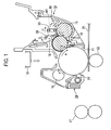
- Fig. 1 is a schematic view of a printer according to a first embodiment of the invention.
- an ID cartridge 10 is an image-forming cartridge of a printer.
- a photoconductive drum 11 rotates in a direction shown by arrow A.
- a charging roller 12 rotates in contact with the photoconductive drum 11 in a direction shown by arrow F and charges the entire circumferential surface of the photoconductive drum 11 uniformly.
- An exposing unit 13 takes the form of, for example, an LED head or a laser scanning device and illuminates the charged surface of the photoconductive drum 11 to form an electrostatic latent image thereon.
- a developing roller 14 rotates in a direction shown by arrow B in contact with the photoconductive drum 11 and supplies toner 30 to the electrostatic latent image to develop the electrostatic latent image into a toner image.
- a developing blade 15 restricts the thickness of a layer of toner formed on the developing roller 14, thereby setting an amount of toner that transfers from the developing roller 4 to the photoconductive drum 11.
- a toner-supplying roller 16 rotates in contact with the developing roller 14 in a direction shown by arrow C.
- the toner-supplying roller 16 is located immediately under a toner cartridge, not shown, and supplies the toner 30 to the developing roller 14.
- An agitator 28 is disposed substantially over a nip formed between the toner-supplying roller 16 and the developing roller 14, and rotates in a direction shown by arrow G, thereby agitating the toner 30.
- a toner-supplying body 33 is disposed in a region AR1 directly over the toner-supplying roller 16, i.e., the toner-supplying body 33 extends substantially parallel to the toner-supplying roller 16 so that they oppose each other or are adjacent to each other.
- the toner-supplying body 33 rotates in a direction shown by arrow H so that the toner-supplying body 33 moves into contact with the toner-supplying roller 16 periodically.
- the developing roller 14, developing blade 15, toner-supplying roller 16, agitator 28, and toner-supplying body 33 cooperate to form a developing unit.
- a transfer roller 22 opposes the photoconductive drum 11 and defines a transfer point between the transfer roller 22 and the photoconductive drum 11.
- the transfer roller 22 transfers a toner image formed on the photoconductive drum 11 onto the recording medium 23.
- the recording medium 23 can be a transparency as well as paper.
- a cleaning unit 24 removes residual toner on the photoconductive drum 11 after transferring the toner image onto the recording medium 23.
- the cleaning unit 24 includes a cleaning blade 25 that is in contact with the surface of the photoconductive drum 11.
- the photoconductive drum 11, charging roller 12, developing unit, toner cartridge, cleaning unit 24 cooperate to form the ID cartridge 10.
- the fixing unit 27 downstream of the transfer point with respect to the transport path of the recording medium 23.
- the fixing unit fixes the toner image on the recording medium 23.
- the exposing unit 13 illuminates the charged surface of the photoconductive drum 11 in accordance with an image signal to form an electrostatic latent image. Subsequently, the developing roller 14 develops the electrostatic latent image with the toner 30 into a toner image. Then, the toner image is transferred by the transfer roller onto the recording medium. The recording medium is advanced to the fixing unit 27 where the toner image is fused into a permanent image.
- the developing unit is of the single component developer type.
- the toner 30 is a single component developer.
- the toner cartridge has an opening that can be opened and closed. When the opening is opened, a predetermined amount of toner 30 falls from the toner cartridge through the opening into the developing unit.
- the agitator 28 rotates, the toner 31 is agitated by the agitator 28 and is supplied to the toner-supplying roller 16.
- the rotation of the toner-supplying body 33 causes the toner 30 to move toward the developing lade 15 and the agitator 28 operates to disperse the toner 30 near the developing blade 15.
- the toner-supplying roller 16 and the developing roller 14 rotate in contact with each other in the same direction but at different speeds.
- the potential difference between the toner-supplying roller 16 and the developing roller 14 causes the toner 30 to move from the toner-supplying roller 16 to the developing roller 14.
- the toner-supplying roller 16 also functions to remove excess toner from the circumferential surface of the developing roller 14.
- the toner-supplying roller 16 is formed of a foamed resilient material such as silicone rubber and urethane rubber, and has a plurality of cells in the shape of a recess in the circumferential surface.
- the toner 30 at the nip is lightly charged due to the friction created by the differences in circumferential speed and rotational direction between the toner-supplying roller 16 and developing roller 14.
- the toner 30 on the developing roller 14 is delivered to the developing blade 15, which in turn restricts the thickness of layer of toner. Then, the layer of toner is brought to the developing point where the toner is attracted to the electrostatic latent image on the photoconductive drum 11 by the Coulomb force, thereby forming a toner image on the photoconductive drum 11.
- the cells in the toner-supplying roller 16 scrape the toner 30 surrounding the toner-supplying roller 16, thereby supplying the toner 30 to the developing roller 14.
- the toner 30 passes the nip formed between the developing roller 14 and the toner-supplying roller 16, the toner 30 is subjected to mechanical stress and heat generated during printing. As a result, the toner 30 loses its fluidity and becomes packed near the toner-supplying roller 16 after repetitive printing cycles over time. The agglomeration of toner tends to prevent the particles of the toner 30 from moving.
- the ability of the toner-supplying roller 16 to scrape the toner 30 is impaired, so that the amount of toner supplied to the developing roller 14 decreases. Especially, because the mechanical stress exerted on the toner in the region AR1 is large, the impaired ability of the toner-supplying roller 16 reduces the toner 30 supplied to the developing roller 14.
- the toner-supplying body 33 is disposed in the region AR1.
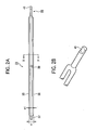
- Fig. 2A is a front view of a toner-supplying body according to the first embodiment.
- Fig. 2B is a fragmentary perspective view of the toner-supplying body.
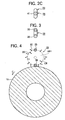
- Fig. 2C is a side view of the toner-supplying body.
- Fig. 3 is a side view of the toner-supplying body.
- Fig. 4 is a cross-sectional view taken along line IV-IV of Fig. 2 .
- the toner-supplying body 33 is formed of, for example, ABS resin, and has substantially the same axial dimension as the toner-supplying roller 16.
- the toner-supplying body 33 includes two parallel rods 35 and 36 having a circular cross section.
- the two rods 35 and 36 are connected together at their longitudinal ends and at their longitudinally middle portions via a connection 39, so that the toner-supplying body 33 has a generally flat overall shape with a width of about 10 mm.
- the toner-supplying body 33 has rotational shafts 37 and 38 formed at its longitudinal end portions about which the toner-supplying body 33 rotates.
- the two rods 35 and 36 are spaced apart by a distance W1, which can be selected depending on the dimension and characteristics of the developing unit.
- a plurality of connections 39 may be employed at appropriate locations between the two rods 35 and 36, thereby preventing the toner-supplying body 33 from deforming or flexing due to the pressure exerted by the toner 30.
- the rotational shaft 38 is in the shape of a deformed cylinder that has been partially cut away in a plane parallel to its longitudinal axis.
- the drive portion 41 is coupled to a drive source, not shown, through a drive force transmitting mechanism such as gears, so that the toner-supplying body 33 is driven in rotation at a predetermined speed. As the toner-supplying body 33 rotates, the rods 35 and 36 are brought alternately into contact engagement with the toner-supplying roller 16.
- Fig. 4 illustrates the positional relation between the toner-supplying body and the toner-supplying roller.
- the rods 35 and 36 move in a circular path CR.
- the rods 35 and 36 alternately contact the toner-supplying roller 16 to push the toner 30 near the circumferential surface of the toner-supplying roller 16 in a direction tangential to the surface of the toner-supplying roller 16.
- This motion of the rods 35 and 36 efficiently supplies the toner 30 to the developing roller 14, preventing printed images from being blurred as well as improving print quality.
- Table 1 lists test results when the toner-supplying body 33 is provided in the developing unit and test results when the toner-supplying body 33 is not provided in the developing unit.
- Table 1 Number of printed pages toner-supplying body is not provided toner-supplying body is provided 2500 ⁇ ⁇ 5000 ⁇ ⁇ 7500 ⁇ ⁇ 10000 ⁇ ⁇ 12500 ⁇ ⁇ 15000 ⁇ ⁇
- Symbol ⁇ indicates that printed images were not blurred. Symbol ⁇ indicates that printed images were blurred.
- Continuous printing was performed on a predetermined number pages of A4 size paper without an image signal sent to the exposing unit 13. Subsequently, printing was performed on pages of A4 size paper with an image signal sent to the exposing unit 23 to print solid images, thereby determining whether printed images were blurred.
- Printing was first performed without an image signal fed to the exposing unit 13. This is done to accurately determine whether agglomeration of toner occurs. The solid image images were printed on the entire print region of the A4 size paper at a print duty of 100%. If a decrease in density of printed image due to insufficient toner supply occurred, it was determined that blurring of image occurred.
- the toner-supplying body 33 is formed of ABS resin.
- the toner-supplying body 33 may be formed of a metal material or other materials, provided that the toner-supplying body 33 can maintain its shape during rotation.
- the rods 35 and 36 have a circular cross-section, the cross section may be of other shapes, for example, a polygon.
- Fig. 5 illustrates another example of the toner-supplying body.
- the toner-supplying body 33 may have a single rod 46 such as that shown in Fig. 5 or more than three rods that extend in parallel to the toner-supplying roller 16.
- the toner-supplying body 33 includes a single crank pin 46
- the toner-supplying body 33 takes the shape of a crank such that the crank pin 46 is eccentric to the rotational shafts 67 and 38.
- the toner-supplying body 33 is preferably formed of two rods 35 and 36 so that the toner-supplying body 33 is well balanced and the toner 30 can smoothly move within the region AR1.
- the toner-supplying body 33 rotates in a direction opposite to the toner-supplying roller 16.
- the toner-supplying body 33 may rotate in the same direction as the toner-supplying roller 16, provided that the toner-supplying body 33 is capable of agitating the toner 30 and pushes the toner outwardly relative to the circular path CR.
- the toner-supplying body 33 may be rotated at the same speed as the toner-supplying roller 16.
- the present embodiment is particularly effective when the toner cartridge is located over the toner-supplying roller 16.
- a color electrophotographic printer includes EP cartridges for respective colors aligned in a line.
- the toner cartridge needs to be positioned over the developing unit and therefore the embodiment is particularly useful.
- Fig. 6 illustrates a toner-supplying body 33 according to a second embodiment.
- Fig. 7 illustrates the operation of the toner-supplying body 33 according to the second embodiment.
- the toner-supplying body 33 has a width h1 smaller than 10 mm and rotates in such a way that the rods 35 and 36 will not contact the toner-supplying roller 16.
- the bottom dead center of the rods 35 and 36 is a distance D1 away from the circumferential surface of the toner-supplying roller 16.
- the toner-supplying body 33 exerts no load on the toner-supplying roller 16. This ensures stable rotation of the toner-supplying roller 16 and therefore a drive source of the toner-supplying body 33 can be a motor having a small rating, which can help reduce production cost of a printer.
- the rotation of the toner-supplying roller 16 in the C direction causes the toner 30 surrounding the toner-supplying roller 16. If the toner-supplying body rotates in such a way that the rods 35 and 36 alternately contact the toner-supplying roller 16, then the toner 30 moved to the toner-supplying roller 16 will be scraped by the cells formed in the circumferential surface of the toner-supplying roller 16.
- the toner-supplying body 33 and the toner-supplying roller 16 are spaced apart by the distance D1, adjacent particles of toner 30 that have moved to the toner-supplying roller 16 due to the rotation of the toner-supplying body 33 will collide with one another in a pileup fashion. In this manner, the collision forces are transmitted from particle to particle. If the distance D1 is large, then the forces are absorbed in the space, failing to push the particles of toner 30 near the toner-supplying roller 16. For this reason, the distance D1 should be less than a certain value.
- the width h1 is 10 mm
- the distance D1 is 0 mm.
- the width h1 is 9.2, 8.4, and 8 mm, the toner-supplying body 33 and toner-supplying roller 16 do not contact each other.
- the distance D1 is in the range of 0 to 0.8 mm, printed images are not blurred after printing 1000 pages.
- the distance D1 is not shorter than 1 mm, the printed images are blurred even though the toner-supplying body 33 is provided.
- the comparison results reveal that if no blurring is detected for 10 , 000 pages there will be no problem within the dates set for safe consumption of the most ID cartridges 10.
- the distance D1 is preferably not longer than 0.8 mm.
- the toner cartridge is located over the toner-supplying roller 16.
- New, fresh toner 30 falls by gravity onto the region AR1 in which the cell 51 scrapes the toner particles, and therefore the toner 30 is subjected to large mechanical stresses.
- New, fresh toner 30 outside of the region AR1 is subjected to relatively small mechanical stresses and therefore the toner 30 will not become packed. Therefore, the particles of toner 30 acquire a large amount of charge and the particles are easy to move.
- a third embodiment is directed to supplying toner from areas outside of the region AR1 into the region AR1.
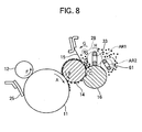
- Fig. 8 is a schematic view of a printer according to the third embodiment.
- Fig. 9 illustrates a toner-supplying body according to the third embodiment.
- a toner-supplying body 33 is disposed directly over a toner-supplying roller 16 and rotates in a direction shown by arrow H in such a fashion that two rods 35 and 36 of the toner-supplying body 33 alternately and periodically contact the circumferential surface of the toner-supplying roller 16.
- the toner-supplying body 33 rotates to define a region AR1.
- At least an additional toner-supplying body 61 is disposed immediately upstream of the region AR1 and rotates in a direction shown by arrow I to define a region AR2 .
- the toner-supplying body 61 extends substantially parallel to the toner-supplying roller 16 so that they oppose each other or are adjacent to each other. It is desirable that the region AR2 opposes at least part of the upper half of the circumferential surface of the toner-supplying roller 16.
- the toner-supplying body 61 is also formed of ABS resin and has substantially the same axial dimension as the toner-supplying roller 16.
- the toner-supplying body 33 includes two parallel rods 62 and 63 having a circular cross section.
- the two rods 62 and 63 are connected to each other at their longitudinal ends and at their longitudinally middle portions via a connection 39.
- the toner-supplying body 61 has rotational shafts, not shown, at its longitudinal ends.
- the two rods 62 and 63 are spaced apart by a distance.
- the toner-supplying body 61 rotates in such a fashion that the two rods 62 and 63 of the toner-supplying body 61 alternately and periodically contact the circumferential surface of the toner-supplying roller 16.
- New, fresh toner 30 within the region AR2 is subjected to relatively small mechanical stress and therefore the toner 30 will not become packed. Therefore, the particles of toner 30 acquire a large amount of charge and the particles are easy to move.
- the rotation of the toner-supplying body 61 in the I direction causes the toner 30 in the region AR2 to move in the C direction into the region AR1.
- the toner 30 can be transferred to the developing roller 14 more efficiently, so that the printed images may be free of blurring and print quality is improved.
Landscapes
- Physics & Mathematics (AREA)
- General Physics & Mathematics (AREA)
- Dry Development In Electrophotography (AREA)
Claims (11)
- Eine Entwicklervorrichtung aufweisend:Einen Entwickler-Trägerkörper (14), der Entwickler auf ein elektrostatisches Latentbild anwendet, das auf eine Bildträgerkörper (11) ausgebildet wird, um das elektrostatische Latentbild mit dem Entwickler in ein sichtbares Bild zu entwickeln;ein erstes Entwickler-Zuführglied (16), das aus einem geschäumten Material ausgebildet ist, wobei das erste Entwickler-Zuführglied (16) in Kontakt mit dem Entwicklerträgerkörper (14) rotiert, um den Entwickler an den Entwickler-Trägerkörper (14) zu liefern;zumindest ein zweites Entwickler-Zuführglied (33, 61), das über dem ersten Entwickler-Zuführglied (16) angeordnet ist, wobei eine äußere Oberfläche des zweiten Entwickler-Zuführglieds (33, 61) direkt über einer oberen Oberfläche des ersten Entwickler-Zuführglieds (16) ist und sich der oberen Oberfläche des ersten Entwickler-Zuführglieds (16) periodisch annähert, um den Entwickler dem ersten Entwickler-Zuführglied (16) zu liefern;wobei wenn die äußere Oberfläche des zweiten Entwickler-Zuführglieds (33, 61) am nächsten zu der oberen Oberfläche des ersten Entwickler-Zuführglieds ist, die äußere Oberfläche des zweiten Entwickler-Zuführglieds (33, 61) und die obere Oberfläche des ersten Entwickler-Zuführglieds (16) durch eine Entfernung nicht größer als 0,8 mm voneinander getrennt sind.
- Die Entwicklervorrichtung nach Anspruch 1, wobei das zweite Entwickler-Zuführglied (33, 61) sich im Wesentlichen parallel zu dem ersten Entwickler-Zuführglied (14) erstreckt und zumindest ein rundstabförmiges Glied (35, 36, 62, 63, 46) mit kreisförmigem Querschnitt einschließt.
- Die Entwicklervorrichtung nach Anspruch 1 oder 2, wobei das rundstabförmige Glied eines einer Mehrzahl von rundstabförmigen Gliedern (35, 36, 62, 63) ist.
- Die Entwicklervorrichtung nach Anspruch 3, wobei der zweite Entwickler-Zuführkörper (33, 61) so ausgebildet ist, dass wenn der zweite Entwickler-Zuführkörper (33, 61) in Betrieb ist, die Mehrzahl von rundstabförmigen Gliedern alternierend sich an das erste Entwickler-Zuführglied (16) annähern.
- Die Entwicklervorrichtung nach einem der Ansprüche 1 bis 4, wobei der Entwickler von über dem ersten Entwickler-Zuführglied (16) zugeführt wird.
- Die Entwicklervorrichtung nach einem der Ansprüche 2 bis 5, wobei das zweite Entwickler-Zuführglied (33, 61) um eine Achse rotiert und das zumindest eine rundstabförmige Glied (35, 36, 62, 63, 46) eines einer Mehrzahl von parallelen Rundstäben ist, die sich parallel zu der Achse erstrecken, wobei die Mehrzahl von Rundstäben alternierend dem ersten Entwickler-Zuführglied (16) am nächsten kommen.
- Die Entwicklervorrichtung nach einem der Ansprüche 1 bis 6, wobei das erste Entwickler-Zuführglied (16) ein Roller mit einer umlaufenden Oberfläche ist und ein zweites Entwickler-Zuführglied (33, 61) ein erstes Unter-Entwickler-Zuführglied (33) und ein zweites Unter-Entwickler-Zuführglied (61) einschließt, wobei jedes von dem ersten Unter-Entwickler-Zuführglied (33) und dem zweiten Unter-Entwickler-Zuführglied (61) sich parallel zu dem ersten Entwickler-Zuführglied (16) erstrecken und rotierbar um einen entsprechenden Schacht sind, der im Wesentlichen parallel zu dem ersten Entwickler-Zuführglied (16) ist;
wobei das erste Unter-Entwickler-Zuführglied (33) und das zweite Unter-Entwickler-Zuführglied (61) jedes in einem unterschiedlichen Bereich rotieren, der einem Teil einer oberen Hälfte der umlaufenden Oberfläche des ersten Entwickler-Zuführglieds (16) gegenüberliegt. - Die Entwicklervorrichtung nach Anspruch 1, wobei wenn die äußere Oberfläche des zweiten Entwickler-Zuführglieds (33, 61) am nächsten zu der oberen Oberfläche des ersten Entwickler-Zuführglieds (16) ist, die äußere Oberfläche des zweiten Entwickler-Zuführglieds (33, 61) und die obere Oberfläche des ersten Entwickler-Zuführglieds (16) in Kontakt miteinander sind.
- Die Entwicklervorrichtung nach Anspruch 7, wobei das erste Unter-Entwickler-Zuführglied (33) und das zweite Unter-Entwickler-Zuführglied (61) in Richtungen entgegengesetzt zu dem ersten Entwickler-Zuführglied (16) rotieren.
- Die Entimicklervorrichtung nach Anspruch 7, wobei das erste Entwickler-Zuführglied (16) und das zweite Entwickler-Zuführglied (33, 61) in Richtungen entgegengesetzt zueinander rotieren.
- Eine Bildformvorrichtung, die eine Entwicklervorrichtung nach einem der Ansprüche 1 bis 10 enthält.
Applications Claiming Priority (2)
| Application Number | Priority Date | Filing Date | Title |
|---|---|---|---|
| JP2003407963 | 2003-12-05 | ||
| JP2003407963A JP4041456B2 (ja) | 2003-12-05 | 2003-12-05 | 現像装置及び画像形成装置 |
Publications (2)
| Publication Number | Publication Date |
|---|---|
| EP1538489A1 EP1538489A1 (de) | 2005-06-08 |
| EP1538489B1 true EP1538489B1 (de) | 2014-03-26 |
Family
ID=34464033
Family Applications (1)
| Application Number | Title | Priority Date | Filing Date |
|---|---|---|---|
| EP04028596.7A Expired - Lifetime EP1538489B1 (de) | 2003-12-05 | 2004-12-02 | Entwicklungsgerät mit einer zweiten Tonerzuführeinheit |
Country Status (3)
| Country | Link |
|---|---|
| US (1) | US7277666B2 (de) |
| EP (1) | EP1538489B1 (de) |
| JP (1) | JP4041456B2 (de) |
Families Citing this family (13)
| Publication number | Priority date | Publication date | Assignee | Title |
|---|---|---|---|---|
| JP5063907B2 (ja) * | 2006-03-13 | 2012-10-31 | 株式会社沖データ | 画像形成ユニット及び画像形成装置 |
| JP4863902B2 (ja) * | 2007-02-23 | 2012-01-25 | 株式会社リコー | 現像装置、プロセスカートリッジ及び画像形成装置 |
| JP4448150B2 (ja) | 2007-02-28 | 2010-04-07 | 株式会社沖データ | 画像形成装置 |
| JP5240551B2 (ja) * | 2008-04-08 | 2013-07-17 | 株式会社リコー | 現像装置、プロセスカートリッジ、画像形成装置 |
| JP5418876B2 (ja) * | 2008-08-27 | 2014-02-19 | 株式会社リコー | 現像装置並びにこれを用いたプロセスカートリッジ及び画像形成装置 |
| JP4926197B2 (ja) * | 2009-04-08 | 2012-05-09 | 株式会社沖データ | 現像装置及び画像形成装置 |
| JP5497416B2 (ja) | 2009-12-09 | 2014-05-21 | 株式会社沖データ | 現像装置およびそれを備えた画像形成装置 |
| JP5477712B2 (ja) * | 2010-02-04 | 2014-04-23 | 株式会社リコー | 現像装置、画像形成装置およびプロセスカートリッジ |
| JP5498205B2 (ja) | 2010-03-05 | 2014-05-21 | 株式会社沖データ | 現像装置および画像形成装置 |
| JP5610968B2 (ja) | 2010-10-15 | 2014-10-22 | 株式会社沖データ | 画像形成ユニット及び画像形成装置 |
| JP6162616B2 (ja) * | 2014-01-31 | 2017-07-12 | 株式会社沖データ | 画像形成ユニット |
| JP2017067802A (ja) * | 2015-09-28 | 2017-04-06 | 株式会社沖データ | 画像形成ユニット及び画像形成装置 |
| JP7528459B2 (ja) * | 2020-02-14 | 2024-08-06 | ブラザー工業株式会社 | 現像カートリッジ |
Family Cites Families (11)
| Publication number | Priority date | Publication date | Assignee | Title |
|---|---|---|---|---|
| GB2163371B (en) * | 1984-08-07 | 1988-04-07 | Ricoh Kk | Developing electrostatic latent images |
| US4873940A (en) * | 1985-10-23 | 1989-10-17 | Ricoh Company, Ltd. | Image developing device |
| JPS62273590A (ja) * | 1986-05-21 | 1987-11-27 | Minolta Camera Co Ltd | 現像装置 |
| JPH07160107A (ja) | 1993-12-01 | 1995-06-23 | Oki Electric Ind Co Ltd | 現像装置 |
| KR100214316B1 (ko) * | 1997-03-14 | 1999-09-01 | 윤종용 | 전자사진 현상방식을 채용한 화상형성장치의 현상기 |
| US6134397A (en) * | 1998-04-09 | 2000-10-17 | Matsushita Electric Industrial Co., Ltd. | Non-magnetic one-component developing apparatus |
| JPH11305532A (ja) | 1998-04-20 | 1999-11-05 | Casio Electronics Co Ltd | 現像装置 |
| JP2000147891A (ja) * | 1998-09-04 | 2000-05-26 | Canon Inc | 現像装置及びプロセスカ―トリッジ及び電子写真画像形成装置及び撹拌部材 |
| JP2001265105A (ja) * | 2000-03-23 | 2001-09-28 | Casio Electronics Co Ltd | 非磁性一成分現像装置 |
| JP4227359B2 (ja) * | 2002-05-13 | 2009-02-18 | キヤノン株式会社 | 現像装置および画像形成装置 |
| JP3986476B2 (ja) * | 2003-07-09 | 2007-10-03 | 株式会社沖データ | 現像装置 |
-
2003
- 2003-12-05 JP JP2003407963A patent/JP4041456B2/ja not_active Expired - Fee Related
-
2004
- 2004-11-30 US US10/999,822 patent/US7277666B2/en not_active Expired - Lifetime
- 2004-12-02 EP EP04028596.7A patent/EP1538489B1/de not_active Expired - Lifetime
Also Published As
| Publication number | Publication date |
|---|---|
| JP4041456B2 (ja) | 2008-01-30 |
| US7277666B2 (en) | 2007-10-02 |
| EP1538489A1 (de) | 2005-06-08 |
| JP2005172842A (ja) | 2005-06-30 |
| US20050123324A1 (en) | 2005-06-09 |
Similar Documents
| Publication | Publication Date | Title |
|---|---|---|
| EP1538489B1 (de) | Entwicklungsgerät mit einer zweiten Tonerzuführeinheit | |
| US8019259B2 (en) | Development device, process unit, and image forming apparatus | |
| US20060216069A1 (en) | Developing unit and image forming apparatus | |
| CN101165608B (zh) | 墨粉传输装置、墨粉补给装置以及使用它们的成像设备 | |
| US20030143001A1 (en) | Developing unit and electro-photographic apparatus | |
| JP3986476B2 (ja) | 現像装置 | |
| US6339690B1 (en) | Electrophotographic apparatus having screening member for recycling toner | |
| EP0636950B1 (de) | Entwicklungsgerät mit einer sich drehenden Entwicklerzufuhreinheit einer Entwicklerträgereinheit | |
| US5852758A (en) | Charge roller displacement mechanism | |
| US7003250B2 (en) | Two component development apparatus and process cartridge | |
| JP2007086312A (ja) | 現像装置及び画像形成装置 | |
| EP2942671B1 (de) | Entwicklungseinheit, bilderzeugungseinheit und bilderzeugungsvorrichtung | |
| US6381424B1 (en) | Toner charge control for image defect reduction | |
| JP4322277B2 (ja) | 現像装置及び画像形成装置 | |
| JP2016114645A (ja) | 現像装置、プロセスユニット及び画像形成装置 | |
| JP2004085877A (ja) | 現像装置 | |
| JP2000019840A (ja) | 現像装置ならびに現像機構を有するユニットおよび画像形成装置 | |
| US7505719B2 (en) | Composite trim bar for developer system | |
| JPH05503373A (ja) | 現像ローラの間隔形成装置 | |
| JP2008197321A (ja) | 現像装置及び画像形成装置 | |
| US8515315B2 (en) | Developing device and image forming apparatus | |
| JP5150478B2 (ja) | 現像装置及びこれを備えた画像形成装置 | |
| JP4382422B2 (ja) | 画像形成装置における現像装置 | |
| JPH0862974A (ja) | 一成分現像装置 | |
| JP2007065486A (ja) | 現像装置、画像形成機構、画像形成装置、現像装置の制御方法 |
Legal Events
| Date | Code | Title | Description |
|---|---|---|---|
| PUAI | Public reference made under article 153(3) epc to a published international application that has entered the european phase |
Free format text: ORIGINAL CODE: 0009012 |
|
| AK | Designated contracting states |
Kind code of ref document: A1 Designated state(s): AT BE BG CH CY CZ DE DK EE ES FI FR GB GR HU IE IS IT LI LT LU MC NL PL PT RO SE SI SK TR |
|
| AX | Request for extension of the european patent |
Extension state: AL BA HR LV MK YU |
|
| 17P | Request for examination filed |
Effective date: 20051202 |
|
| AKX | Designation fees paid |
Designated state(s): DE FR GB NL |
|
| 17Q | First examination report despatched |
Effective date: 20120703 |
|
| GRAJ | Information related to disapproval of communication of intention to grant by the applicant or resumption of examination proceedings by the epo deleted |
Free format text: ORIGINAL CODE: EPIDOSDIGR1 |
|
| GRAP | Despatch of communication of intention to grant a patent |
Free format text: ORIGINAL CODE: EPIDOSNIGR1 |
|
| INTG | Intention to grant announced |
Effective date: 20131009 |
|
| RIN1 | Information on inventor provided before grant (corrected) |
Inventor name: KAWANO, MASAHIRO Inventor name: ODA, YUKIYOSHI |
|
| GRAS | Grant fee paid |
Free format text: ORIGINAL CODE: EPIDOSNIGR3 |
|
| GRAA | (expected) grant |
Free format text: ORIGINAL CODE: 0009210 |
|
| AK | Designated contracting states |
Kind code of ref document: B1 Designated state(s): DE FR GB NL |
|
| REG | Reference to a national code |
Ref country code: GB Ref legal event code: FG4D |
|
| REG | Reference to a national code |
Ref country code: DE Ref legal event code: R096 Ref document number: 602004044668 Country of ref document: DE Effective date: 20140508 |
|
| REG | Reference to a national code |
Ref country code: NL Ref legal event code: T3 |
|
| REG | Reference to a national code |
Ref country code: DE Ref legal event code: R097 Ref document number: 602004044668 Country of ref document: DE |
|
| PLBE | No opposition filed within time limit |
Free format text: ORIGINAL CODE: 0009261 |
|
| STAA | Information on the status of an ep patent application or granted ep patent |
Free format text: STATUS: NO OPPOSITION FILED WITHIN TIME LIMIT |
|
| 26N | No opposition filed |
Effective date: 20150106 |
|
| REG | Reference to a national code |
Ref country code: DE Ref legal event code: R097 Ref document number: 602004044668 Country of ref document: DE Effective date: 20150106 |
|
| REG | Reference to a national code |
Ref country code: FR Ref legal event code: PLFP Year of fee payment: 12 |
|
| REG | Reference to a national code |
Ref country code: FR Ref legal event code: PLFP Year of fee payment: 13 |
|
| REG | Reference to a national code |
Ref country code: FR Ref legal event code: PLFP Year of fee payment: 14 |
|
| PGFP | Annual fee paid to national office [announced via postgrant information from national office to epo] |
Ref country code: NL Payment date: 20201113 Year of fee payment: 17 |
|
| PGFP | Annual fee paid to national office [announced via postgrant information from national office to epo] |
Ref country code: FR Payment date: 20201112 Year of fee payment: 17 Ref country code: DE Payment date: 20201118 Year of fee payment: 17 Ref country code: GB Payment date: 20201126 Year of fee payment: 17 |
|
| REG | Reference to a national code |
Ref country code: DE Ref legal event code: R119 Ref document number: 602004044668 Country of ref document: DE |
|
| REG | Reference to a national code |
Ref country code: NL Ref legal event code: MM Effective date: 20220101 |
|
| GBPC | Gb: european patent ceased through non-payment of renewal fee |
Effective date: 20211202 |
|
| PG25 | Lapsed in a contracting state [announced via postgrant information from national office to epo] |
Ref country code: NL Free format text: LAPSE BECAUSE OF NON-PAYMENT OF DUE FEES Effective date: 20220101 |
|
| PG25 | Lapsed in a contracting state [announced via postgrant information from national office to epo] |
Ref country code: GB Free format text: LAPSE BECAUSE OF NON-PAYMENT OF DUE FEES Effective date: 20211202 Ref country code: DE Free format text: LAPSE BECAUSE OF NON-PAYMENT OF DUE FEES Effective date: 20220701 |
|
| PG25 | Lapsed in a contracting state [announced via postgrant information from national office to epo] |
Ref country code: FR Free format text: LAPSE BECAUSE OF NON-PAYMENT OF DUE FEES Effective date: 20211231 |