EP1538386A2 - Stativ - Google Patents
Stativ Download PDFInfo
- Publication number
- EP1538386A2 EP1538386A2 EP05000973A EP05000973A EP1538386A2 EP 1538386 A2 EP1538386 A2 EP 1538386A2 EP 05000973 A EP05000973 A EP 05000973A EP 05000973 A EP05000973 A EP 05000973A EP 1538386 A2 EP1538386 A2 EP 1538386A2
- Authority
- EP
- European Patent Office
- Prior art keywords
- stand
- axis
- support arm
- weight
- column
- Prior art date
- Legal status (The legal status is an assumption and is not a legal conclusion. Google has not performed a legal analysis and makes no representation as to the accuracy of the status listed.)
- Granted
Links
- 230000008878 coupling Effects 0.000 claims abstract description 20
- 238000010168 coupling process Methods 0.000 claims abstract description 20
- 238000005859 coupling reaction Methods 0.000 claims abstract description 20
- 230000005540 biological transmission Effects 0.000 claims description 7
- NJPPVKZQTLUDBO-UHFFFAOYSA-N novaluron Chemical compound C1=C(Cl)C(OC(F)(F)C(OC(F)(F)F)F)=CC=C1NC(=O)NC(=O)C1=C(F)C=CC=C1F NJPPVKZQTLUDBO-UHFFFAOYSA-N 0.000 claims description 2
- 230000005484 gravity Effects 0.000 description 2
- 238000010276 construction Methods 0.000 description 1
- 238000004519 manufacturing process Methods 0.000 description 1
- 230000001629 suppression Effects 0.000 description 1
- 239000000725 suspension Substances 0.000 description 1
Images

Classifications
-
- F—MECHANICAL ENGINEERING; LIGHTING; HEATING; WEAPONS; BLASTING
- F16—ENGINEERING ELEMENTS AND UNITS; GENERAL MEASURES FOR PRODUCING AND MAINTAINING EFFECTIVE FUNCTIONING OF MACHINES OR INSTALLATIONS; THERMAL INSULATION IN GENERAL
- F16M—FRAMES, CASINGS OR BEDS OF ENGINES, MACHINES OR APPARATUS, NOT SPECIFIC TO ENGINES, MACHINES OR APPARATUS PROVIDED FOR ELSEWHERE; STANDS; SUPPORTS
- F16M13/00—Other supports for positioning apparatus or articles; Means for steadying hand-held apparatus or articles
- F16M13/02—Other supports for positioning apparatus or articles; Means for steadying hand-held apparatus or articles for supporting on, or attaching to, an object, e.g. tree, gate, window-frame, cycle
-
- A—HUMAN NECESSITIES
- A61—MEDICAL OR VETERINARY SCIENCE; HYGIENE
- A61B—DIAGNOSIS; SURGERY; IDENTIFICATION
- A61B90/00—Instruments, implements or accessories specially adapted for surgery or diagnosis and not covered by any of the groups A61B1/00 - A61B50/00, e.g. for luxation treatment or for protecting wound edges
- A61B90/20—Surgical microscopes characterised by non-optical aspects
- A61B90/25—Supports therefor
-
- F—MECHANICAL ENGINEERING; LIGHTING; HEATING; WEAPONS; BLASTING
- F16—ENGINEERING ELEMENTS AND UNITS; GENERAL MEASURES FOR PRODUCING AND MAINTAINING EFFECTIVE FUNCTIONING OF MACHINES OR INSTALLATIONS; THERMAL INSULATION IN GENERAL
- F16M—FRAMES, CASINGS OR BEDS OF ENGINES, MACHINES OR APPARATUS, NOT SPECIFIC TO ENGINES, MACHINES OR APPARATUS PROVIDED FOR ELSEWHERE; STANDS; SUPPORTS
- F16M11/00—Stands or trestles as supports for apparatus or articles placed thereon ; Stands for scientific apparatus such as gravitational force meters
- F16M11/02—Heads
- F16M11/04—Means for attachment of apparatus; Means allowing adjustment of the apparatus relatively to the stand
- F16M11/06—Means for attachment of apparatus; Means allowing adjustment of the apparatus relatively to the stand allowing pivoting
- F16M11/10—Means for attachment of apparatus; Means allowing adjustment of the apparatus relatively to the stand allowing pivoting around a horizontal axis
-
- F—MECHANICAL ENGINEERING; LIGHTING; HEATING; WEAPONS; BLASTING
- F16—ENGINEERING ELEMENTS AND UNITS; GENERAL MEASURES FOR PRODUCING AND MAINTAINING EFFECTIVE FUNCTIONING OF MACHINES OR INSTALLATIONS; THERMAL INSULATION IN GENERAL
- F16M—FRAMES, CASINGS OR BEDS OF ENGINES, MACHINES OR APPARATUS, NOT SPECIFIC TO ENGINES, MACHINES OR APPARATUS PROVIDED FOR ELSEWHERE; STANDS; SUPPORTS
- F16M11/00—Stands or trestles as supports for apparatus or articles placed thereon ; Stands for scientific apparatus such as gravitational force meters
- F16M11/20—Undercarriages with or without wheels
- F16M11/2007—Undercarriages with or without wheels comprising means allowing pivoting adjustment
- F16M11/2021—Undercarriages with or without wheels comprising means allowing pivoting adjustment around a horizontal axis
-
- F—MECHANICAL ENGINEERING; LIGHTING; HEATING; WEAPONS; BLASTING
- F16—ENGINEERING ELEMENTS AND UNITS; GENERAL MEASURES FOR PRODUCING AND MAINTAINING EFFECTIVE FUNCTIONING OF MACHINES OR INSTALLATIONS; THERMAL INSULATION IN GENERAL
- F16M—FRAMES, CASINGS OR BEDS OF ENGINES, MACHINES OR APPARATUS, NOT SPECIFIC TO ENGINES, MACHINES OR APPARATUS PROVIDED FOR ELSEWHERE; STANDS; SUPPORTS
- F16M11/00—Stands or trestles as supports for apparatus or articles placed thereon ; Stands for scientific apparatus such as gravitational force meters
- F16M11/20—Undercarriages with or without wheels
- F16M11/2007—Undercarriages with or without wheels comprising means allowing pivoting adjustment
- F16M11/2035—Undercarriages with or without wheels comprising means allowing pivoting adjustment in more than one direction
- F16M11/2064—Undercarriages with or without wheels comprising means allowing pivoting adjustment in more than one direction for tilting and panning
-
- F—MECHANICAL ENGINEERING; LIGHTING; HEATING; WEAPONS; BLASTING
- F16—ENGINEERING ELEMENTS AND UNITS; GENERAL MEASURES FOR PRODUCING AND MAINTAINING EFFECTIVE FUNCTIONING OF MACHINES OR INSTALLATIONS; THERMAL INSULATION IN GENERAL
- F16M—FRAMES, CASINGS OR BEDS OF ENGINES, MACHINES OR APPARATUS, NOT SPECIFIC TO ENGINES, MACHINES OR APPARATUS PROVIDED FOR ELSEWHERE; STANDS; SUPPORTS
- F16M11/00—Stands or trestles as supports for apparatus or articles placed thereon ; Stands for scientific apparatus such as gravitational force meters
- F16M11/20—Undercarriages with or without wheels
- F16M11/2007—Undercarriages with or without wheels comprising means allowing pivoting adjustment
- F16M11/2035—Undercarriages with or without wheels comprising means allowing pivoting adjustment in more than one direction
- F16M11/2078—Undercarriages with or without wheels comprising means allowing pivoting adjustment in more than one direction with ball-joint
-
- F—MECHANICAL ENGINEERING; LIGHTING; HEATING; WEAPONS; BLASTING
- F16—ENGINEERING ELEMENTS AND UNITS; GENERAL MEASURES FOR PRODUCING AND MAINTAINING EFFECTIVE FUNCTIONING OF MACHINES OR INSTALLATIONS; THERMAL INSULATION IN GENERAL
- F16M—FRAMES, CASINGS OR BEDS OF ENGINES, MACHINES OR APPARATUS, NOT SPECIFIC TO ENGINES, MACHINES OR APPARATUS PROVIDED FOR ELSEWHERE; STANDS; SUPPORTS
- F16M13/00—Other supports for positioning apparatus or articles; Means for steadying hand-held apparatus or articles
- F16M13/02—Other supports for positioning apparatus or articles; Means for steadying hand-held apparatus or articles for supporting on, or attaching to, an object, e.g. tree, gate, window-frame, cycle
- F16M13/027—Ceiling supports
-
- G—PHYSICS
- G02—OPTICS
- G02B—OPTICAL ELEMENTS, SYSTEMS OR APPARATUS
- G02B7/00—Mountings, adjusting means, or light-tight connections, for optical elements
- G02B7/001—Counterbalanced structures, e.g. surgical microscopes
-
- A—HUMAN NECESSITIES
- A61—MEDICAL OR VETERINARY SCIENCE; HYGIENE
- A61B—DIAGNOSIS; SURGERY; IDENTIFICATION
- A61B90/00—Instruments, implements or accessories specially adapted for surgery or diagnosis and not covered by any of the groups A61B1/00 - A61B50/00, e.g. for luxation treatment or for protecting wound edges
- A61B90/20—Surgical microscopes characterised by non-optical aspects
-
- F—MECHANICAL ENGINEERING; LIGHTING; HEATING; WEAPONS; BLASTING
- F16—ENGINEERING ELEMENTS AND UNITS; GENERAL MEASURES FOR PRODUCING AND MAINTAINING EFFECTIVE FUNCTIONING OF MACHINES OR INSTALLATIONS; THERMAL INSULATION IN GENERAL
- F16M—FRAMES, CASINGS OR BEDS OF ENGINES, MACHINES OR APPARATUS, NOT SPECIFIC TO ENGINES, MACHINES OR APPARATUS PROVIDED FOR ELSEWHERE; STANDS; SUPPORTS
- F16M2200/00—Details of stands or supports
- F16M2200/04—Balancing means
- F16M2200/044—Balancing means for balancing rotational movement of the undercarriage
Definitions
- the invention relates to a stand, in particular for receiving a medical device, For example, a surgical microscope, with a column stand, where a first Carrier arm is arranged and with a second support arm, which on the first support arm is received and relative to the first support arm about a first axis and a can be moved from the first axis different second axis, in which Generating a restoring force for the second support arm about the first axis is provided movable weight, and means are provided for coupling, which is the Couple weight with a movement of the second carrier arm about the first axis.
- a medical device For example, a surgical microscope, with a column stand, where a first Carrier arm is arranged and with a second support arm, which on the first support arm is received and relative to the first support arm about a first axis and a can be moved from the first axis different second axis, in which Generating a restoring force for the second support arm about the first axis is provided movable weight, and
- Such a tripod is known from US 4,548,373.
- a tripod for one Surgical microscope described which has a first column stand, on which a vertical axis of rotation a first support arm is pivotally received.
- This first Carrier arm carries with one end portion a second support arm.
- This second carrier arm may be horizontal to the first support arm in a hinge mount about a first one aligned axis of rotation and about the first horizontally oriented axis of rotation be moved vertically oriented further axis of rotation.
- a balance weight On the second support arm is a balance weight, which is to compensate for the second support arm absorbed load weight of the surgical microscope is used.
- a tripod for receiving a lighting unit comprises a column stand, on which a support arm is received.
- This Carrier arm can be rotated with respect to the column stand in a horizontal plane and be pivoted in a vertical plane to the column stand.
- a movably arranged weight provided with the support arm is in active connection.
- US 5,494,034 discloses a floor stand comprising a column stand on which a Carrier device is arranged with a first and a second support arm.
- the first Carrier arm is rotatably mounted on the column stand.
- At one end of the first Stromarmes the second support arm is pivotally mounted and respect. Two to the first support arm orthogonal axes movable.
- a third arm is in turn rotatably disposed one end of the second support arm and stops with a hinge a surgical instrument.
- the Articulated connection of the second and third support arm and the hinge on which the surgical instrument is arranged to combine with toothed belt drives which the movement of the third support arm and the surgical instrument to a Pair weight compensation mechanism.
- This weight compensation mechanism includes Two balance weights, which are added to lever arms and with a forked formed holding device of the first support arm in the region of a Articulated be worn by the first and second support arm.
- WO 97/13997 is a ground stand with counterbalance for receiving a Operating microscopes known.
- This tripod has a column stand on which a Spoarmvorraum is received with a first and a second support arm. It is the first support arm is pivotally attached to the upright column.
- the second support arm is in turn rotatably mounted on the first support arm.
- the surgical microscope is in received an end portion of the second support arm.
- To compensate for the Operation microscope attacking weight are on the first and second support arm each counterweights provided. These counterweights balance the first and second support arm according to the principle of a beam balance.
- the object of the invention is to provide a tripod, on the one hand space-saving dimensions On the other hand, however, allows a heavy, recorded on the tripod medical device can easily be moved in any direction.
- the weight in the range of a column stand movably arranged. Under a weight that moves in the area of a column stand is arranged, it is understood a weight which is close to or in the Stand column is located and whose position can be changed there.
- a weight which is close to or in the Stand column is located and whose position can be changed there.
- inertial forces By clicking on or can be arranged directly at a rotational axis of the column stand, inertial forces be minimized, the rotation of the tripod about the axis of rotation of the column stand occur.
- These inertial forces are caused by the weight and effect of the relevant tripod movement about the corresponding axis of rotation with a counter-torque opposite.
- Such an arrangement of the weight thus ensures easy rotation of the tripod about an axis of the column stand.
- such a tilt-stable tripod with low equipment focus By clicking on or can be arranged directly at a rotational axis of the column stand, inertial forces be minimized, the rotation of the tripod about the
- the weight in the tripod invention acts as a counterweight. In this way can be made while maintaining a simple design by zooming in or out the counterweight a restoring force for a different weight of the Tripod recorded medical device can be adjusted.
- the means for coupling are formed as a cable. On In this way, the coupling means can easily be attached to a desired tripod geometry be adjusted.
- the means for coupling are designed as linkage arrangement. In this way, a tripod is created, the high mechanical loads withstand.
- the means for generating a restoring force are the same on the second arm attacking weight due to a load arranged thereon out. In this way it is possible to balance the tripod completely, so that the am Tripod recorded medical device can be moved almost powerless.
- a counterweight can be arranged in the area of the column stand, so as to provide a non-tilting tripod whose center of gravity is in the area of the column of posts lies.
- For the cable pull can be a deflection for guiding the cable near a Stand column can be provided. In this way it is possible to enter the column Balance weight to lead.
- the tripod is the first carrier arm to a stand column rotatable substantially parallel axis of rotation. This will be a tripod with large workspace.
- the means for coupling may be interrupted at least once. In this way an easy mobility of the tripod is guaranteed.
- a cable as a means for coupling or a linkage arrangement is a twisting or twisting of cable or linkage avoided.
- the means for Coupling assigned as a rotational decoupler freewheeling hinge, which a Feeding back a movement of the second arm about at least one of the two axes the means for generating a restoring force avoids.
- This will be a tripod created in which a restoring moment for an axis to compensate for a corresponding tripod load no effect on the mobility of the tripod to cause another axis.
- a freewheeling pivot allows in particular the twisting of a cable as a means to prevent coupling.
- first axis is substantially orthogonal to the second Axis.
- substantially orthogonal orientation of first and second Axis is understood to mean an orientation of these axes, in which they are within one Tolerance interval by ⁇ 20 ° perpendicular to each other. In this way one becomes Carrier arm system provided with two degrees of freedom of movement, whose gear from a Users of the tripod can be easily detected.
- the first and the second axis are at a distance from each other arranged. In this way, a mechanically simple design of the tripod joints allows.
- the freewheel swivel joint is located on one of the axes. On this way can be used as a freewheel swivel a swivel block, which almost causes complete suppression of feedback.
- the cable is at least partially via rollers guided along one of the axes. In this way, a particularly low-friction Rope guide created.
- the means for feedback are designed as linkages, which comprises a transmission rod displaceable along one of the axes.
- the tripod comprises means for generating a restoring force a lever arm which is arranged on one of the support arms and a counterweight carries, wherein the means for coupling a pivoting movement of the lever arm to a Couple pivot movement of the second carrier arm.
- the tripod is designed as a floor stand. In this way An easily transportable tripod is provided.
- tripod with this design is designed as a ceiling stand, so is a special space-saving tripod construction created.
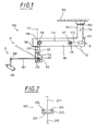
- FIG. 1 shows a tripod 100 designed as a ceiling stand, which is supported by means of a Stand column 101 with swivel 102 on a ceiling 103, for example in a Operating room is hung up.
- a tripod 100 designed as a ceiling stand
- the stand column 101 with swivel 102 mounted on a suitable stand base.
- the column stand 101 is connected to a first arm 104 acting as a support arm, at the in an end region via a Hubarmango 105 with swivel 106 a second support arm 107 is received.
- This second carrier arm 107 acts as a lift arm.
- He has in an end region of a joint 108 to which a surgical microscope 109 as a medical Device is stored.
- the support arm 104 may be due to the pivot 102 on the stator column 101 to a to the column stand parallel rotation axis 110 are pivoted.
- the pivot 106 in Hubarmango 105 ensures that the second support arm 107 about an axis of rotation 111th is pivotable.
- the axis of rotation 111 runs substantially parallel to the column stand 101 and lies in the explained with reference to Figure 1 embodiment in the Plane. Under a substantially parallel course of rotation axis 111 and Stand column 101 is understood to mean a course, for example, due to Manufacturing tolerances deviates from a strict parallel course.
- the second support arm 107 at a distance from the first support arm 104th mounted pivotably on a pivot axis 112.
- This pivot axis runs on the one hand orthogonal to the axis of rotation 111 of Hubarmarris 105 and is in the figure oriented perpendicular to the plane of the drawing.
- This suspension of Hubarmarris 105 allows it, for example, the support arm 107 from a pivot position A in one to move by means of dashed lines indicated pivoting position A '.
- a counterweight 113 is provided in the tripod 100.
- This counterweight 113 serves as a means for generating a restoring force.
- the counterweight 113 is arranged in the region of the column stand 101. This becomes an inertia effect of the counterweight 113 during a movement of the column stand 101 with the Carrier arms 104 and 107 around the axis of rotation 110 minimizes at which the counterweight engages causes unwanted counter-torque and thus the movement about the rotation axis 110th would complicate. Furthermore, so is the overall focus of the tripod recorded surgical microscope in the region of the column stand 101 in the vicinity of Rotation axis 110 and it are the pivot joint 102 such bearing forces minimized, the oriented perpendicular to its axis of rotation 110.
- the counterweight 113 is connected via a cable 114 as a means for coupling with a pulley 115, via which a moment applied to the pivot axis 112 which compensates for the weight of the operation microscope 109.
- This cable 114 thus couples the counterweight 113 with a movement of the second support arm 107 the pivot axis 112.
- the cable 114 is from the guide roller 115 along the axis of rotation 111 of the rotary joint 106 guided in the Hubarmong 105.
- a pulley 116 By means of a pulley 116, it is deflected toward the first carrier arm 104 and onto a deflection roller 117 placed at which attacks the counterweight 113 caused by counter-torque.
- the pulleys 116 and 117 on Rotary axes 118, 119 mounted, respectively to the first support arm 104 and the drawing plane are oriented vertically.
- the counterweight 113 engages the guide roller 117 with a Lever arm 120 on.
- Counterweight 113 moves from the position B in the position B ', in the corresponding Way is indicated by dashed lines.
- the resulting lever arms are different and to the momentary Adjusted position of the second support arm 108. This ensures that despite one changing load torque, which acts on the pivot axis 112 when the second Carrier arm 107 is moved from position A to position A ', by means of the counterweight 113 is generated just needed balancing force.
- a freewheel swivel 121 In the area of the Hubarmarmes 105 is in the cable 114 on the axis of rotation 111 a freewheel swivel 121 provided.
- This freewheeling pivot 121 causes at a Movement of the second support arm 107 about the axis of rotation 111, the cable of the cable 114th not twisted.
- the freewheel hinge 121 divides the cable 114 into one the second support arm 107 associated portion 122 and a portion 123, the Counterweight 113 points.
- These respective sections 122 and 123 of the cable 114 are thus freely rotatable relative to each other, so that a rotational movement of the second support arm 107th about the axis of rotation 111 is completely decoupled from a movement of the counterweight 113.
- a rotational movement of the second carrier arm 107 leads about the axis of rotation 111 not to a feedback of this rotational movement in the cable pull section 123, at the counterweight 113 is arranged.
- the inertia of the counterweight 113 at a rotation of the second Carrier arm 107 is minimized about the axis of rotation 111 of the pivot 106 on Hubarmango.
- a possible embodiment for the freewheel hinge 120 of Figure 1 is in the figure 2 shown.
- This freewheel hinge is designed as a ball-bearing pivot joint 200.
- the counterweight 113 of Figure 1 facing portion of the cable 201 is provided with a Ball carrier plate 202 connected.
- the pointing to the lifting arm 107 of Figure 1 section the cable 205 is in turn fixed to a ball bearing housing 203.
- balls 204 are arranged between the Ball carrier plate 202 and the ball bearing housing 203.
- This structure allows that upon rotation of the second support arm 107 from Figure 1 about the axis of rotation 111 of Figure 1, the ball bearing housing 203 together with the to the second carrier arm facing portion of the cable 205 can rotate freely without the to the counterweight 113 facing portion of the cable 201 to twist significantly.
- FIG. 3 shows, as a further embodiment of the invention, a stand 300, the principle of which Structure corresponds to that of the tripod 100 of Figure 1.
- the tripod 300 is designed as a ceiling stand and by means of a column stand 301 with hinge 302 on a ceiling 303, for example in an operating room suspended.
- the stand 300 it is also possible to perform the stand 300 as a floor stand, in which the stand column 301 with the hinge 302 is mounted on a stand base.
- first support arm 304 On the stand column 301 a acting as a support arm first support arm 304 is attached.
- This first support arm 304 is a Hubarmarme 305 associated with pivot 306, at a second support arm 307 is received.
- This second carrier arm 307 acts as Lifting arm. It is received on Hubarmani 305 with a joint 308 and stops with a joint 310, a surgical microscope 309 as a medical device.
- the first support arm 304 by means of swivel 302 pivoted on the stand column 301 about a rotation axis 311 parallel to the stand column become.
- the second support arm 307 is connected to the pivot 306 in the Hubarmarme 305 to the axis of rotation 312 is movable, which is substantially parallel to the stator column 301 and in the embodiment of Figure 3 is also in the drawing plane.
- the second Carrier arm 307 is on Hubarmarme 305 with the joint 308 on a pivot axis 313rd which is oriented orthogonal to the axis of rotation 312 of the Hubarmitatis 305 and in embodiment shown extends perpendicular to the plane.
- This arrangement of Pivot axis 313 makes it possible, for example, the support arm 307 in the stand 300 a pivot position A in a direction indicated by dashed lines pivot position B to move.
- a counterweight 314 is provided, which serves as a means for generating a restoring force serves.
- This counterweight 314 is arranged in the region of the column stand 301. Consequently is also the center of gravity of the overall system in the vicinity of the axis of rotation 311 of Swivel 302 of the pedestal column 301 and the inertia effect of the counterweight 314 is minimized.
- the counterweight 314 is connected via a linkage arrangement as a means for coupling with the second support arm 307 connected.
- This linkage assembly includes a counterweight 314 supporting lever arm 315, which is connected to a perpendicular to the stand column 301 and the first support arm 304 oriented axis of rotation 316 is mounted.
- This lever arm 315 includes a ball joint 317, which at the respect to the rotation axis 316 to the counterweight 314th located opposite side.
- a transmission rod 318 connected along the axis of rotation 312 of the pivot 306 in the Hubarmisme 305 is guided.
- This transmission rod 318 is a ball joint 319 attached to the second support arm 307.
- the ball joint 317 comprises a ball joint with a sleeve which releases the lever arm 315 slidably receives.
- the ball joint 319 is on the second Carrier arm 307 formed.
- the transmission rod 318 is along the rotation axis 312 slidably guided between the rollers 320 and 321 and includes a freewheel hinge 322.
- the freewheeling hinge 322 may be correspondingly to the freewheeling hinge 121 may be formed from FIG. It divides the transmission rod 318 into a section 323, which is associated with the second support arm 307 and a portion 324, the to the counterweight 314 points.
- the freewheel hinge 322 causes the respective sections 323 and 324 of the Transmission rod 318 are freely rotatable to each other.
Landscapes
- Engineering & Computer Science (AREA)
- General Engineering & Computer Science (AREA)
- Mechanical Engineering (AREA)
- Health & Medical Sciences (AREA)
- Surgery (AREA)
- Physics & Mathematics (AREA)
- Life Sciences & Earth Sciences (AREA)
- Optics & Photonics (AREA)
- Medical Informatics (AREA)
- Pathology (AREA)
- Nuclear Medicine, Radiotherapy & Molecular Imaging (AREA)
- General Physics & Mathematics (AREA)
- Biomedical Technology (AREA)
- Heart & Thoracic Surgery (AREA)
- Oral & Maxillofacial Surgery (AREA)
- Molecular Biology (AREA)
- Animal Behavior & Ethology (AREA)
- General Health & Medical Sciences (AREA)
- Public Health (AREA)
- Veterinary Medicine (AREA)
- Microscoopes, Condenser (AREA)
- Manipulator (AREA)
- Accessories Of Cameras (AREA)
Abstract
Description
- Figur 1:
- eine erste Ausführungsform eines Stativs;
- Figur 2:
- den Aufbau eines Freilaufdrehgelenks in einem Stativ aus Figur 1; und
- Figur 3:
- eine zweite Ausführungsform eines Stativs.
Claims (18)
- Stativ (100, 300), insbesondere zur Aufnahme eines medizinischen Geräts, beispielsweise eines Operationsmikroskops (109, 309),dadurch gekennzeichnet, dassmit einer Ständersäule (101, 301), an der ein erster Trägerarm (104, 304) angeordnet ist, undmit einem zweiten Trägerarm (107, 307), der an dem ersten Trägerarm (104, 304) aufgenommen ist und relativ zu dem ersten Trägerarm (104, 304) um eine erste Achse (112, 313) und um eine von der ersten Achse verschiedenen zweiten Achse (111, 312) bewegt werden kann,bei dem zum Erzeugen einer Rückstellkraft für den zweiten Trägerarm (107, 307) um die erste Achse (112, 313) ein bewegbares Gewicht (113, 314) vorgesehen ist, undMittel zum Koppeln (114, 315 - 319) vorgesehen sind, welche das Gewicht (113, 314) mit einer Bewegung des zweiten Trägerarmes (107, 307) um die erste Achse (111, 313) koppeln,
das bewegbare Gewicht (113, 314) im Bereich der Ständersäule (101, 301) angeordnet ist. - Stativ gemäß Anspruch 1, dadurch gekennzeichnet, daß zur Kopplung von Gewicht (113) und zweitem Trägerarm (107) ein Seilzug (114) vorgesehen ist.
- Stativ gemäß Anspruch 2, dadurch gekennzeichnet, dass eine Umlenkung (116) zum Führen des Seilzugs (114) vorgesehen ist.
- Stativ gemäß Anspruch 2 oder 3, dadurch gekennzeichnet, dass der Seilzug (114) wenigstens abschnittsweise über Rollen (115, 116) entlang einer der Achsen (111) geführt ist.
- Stativ gemäß einem der Ansprüche 2 bis 4, dadurch gekennzeichnet, dass über den Seilzug (114) eine ausgleichende Rückstellkraft übertragen wird, die an dem zweiten Trägerarm (107) in einem Abstand von der Ständersäule (101) angreift, wobei der Seilzug (114) in eine Parallelrichtung zur Ständersäule (101) umgelenkt ist.
- Stativ gemäß Anspruch 1, dadurch gekennzeichnet, dass zur Kopplung von Gewicht (314) und Trägerarm (307) eine Gestängeanordnung (315 - 319) vorgesehen ist.
- Stativ gemäß Anspruch 6, dadurch gekennzeichnet, dass die Gestängeanordnung eine entlang einer der Achsen verschiebbare Übertragungsstange (318) umfasst.
- Stativ gemäß einem der Ansprüche 1 bis 7, dadurch gekennzeichnet, dass der erste Trägerarm (104, 304) an einer Ständersäule (101, 301) angeordnet ist und um eine Achse (110, 311) der Ständersäule (101, 301) gedreht werden kann, wobei das Gewicht (113, 314) im Bereich der Ständersäule (101, 301) bewegbar ist.
- Stativ gemäß einem der Ansprüche 1 bis 8, dadurch gekennzeichnet, dass das Gewicht (113, 314) eine an dem zweiten Arm (107, 307) angreifende Gewichtskraft aufgrund einer daran angeordneten Last (109, 309) ausgleicht.
- Stativ gemäß einem der Ansprüche 1 bis 9, dadurch gekennzeichnet, daß der erste Trägerarm (104, 304) um eine zu der Ständersäule (101, 301) im wesentlichen parallele Drehachse (110, 311) drehbar ist.
- Stativ gemäß einem der Ansprüche 1 bis 10, dadurch gekennzeichnet, dass die Mittel zum Koppeln (114, 315 - 319) zum Unterdrücken einer Rückkopplung einer Bewegung des zweiten Trägerarms (107, 307) um die zweite Achse (111, 312) zu dem Gewicht ein als Drehentkopplung wirkendes Freilaufdrehgelenk (121, 322) aufweisen.
- Stativ gemäß Anspruch 11, dadurch gekennzeichnet, dass das Freilaufdrehgelenk (121, 322) auf einer der Achsen (111, 312) liegt.
- Stativ gemäß einer der Ansprüche 11 oder 12, dadurch gekennzeichnet, dass das Freilaufdrehgelenk (121, 322) als kugelgelagertes Drehgelenk (200) oder als Wirbelblock ausgeführt ist.
- Stativ gemäß einem der Ansprüche 1 bis 13, dadurch gekennzeichnet, dass die erste Achse (112, 313) im wesentlichen orthogonal zur zweiten Achse (111, 312) ist.
- Stativ gemäß einem der Ansprüche 1 bis 14, dadurch gekennzeichnet, dass die erste Achse (112, 313) und die zweite Achse (111, 312) in Abstand voneinander angeordnet sind.
- Stativ gemäß einem der Ansprüche 1 bis 15, dadurch gekennzeichnet, dass dem bewegbaren Gewicht (113, 314) ein Hebelarm (120, 315) zugeordnet ist, der an einem der Trägerarme (104, 304) angeordnet ist und das Gewicht (113, 314) trägt, wobei die Mittel zum Koppeln (114, 315 - 319) eine Schwenkbewegung des Hebelarmes (120, 315) an eine Schwenkbewegung des zweiten Trägerarmes (107, 307) koppeln.
- Stativ gemäß einem der Ansprüche 1 bis 16, dadurch gekennzeichnet, dass das Stativ als Bodenstativ ausgebildet ist.
- Stativ gemäß einem der Ansprüche 1 bis 17, dadurch gekennzeichnet, dass das Stativ als Deckenstativ (100, 300) ausgebildet ist.
Applications Claiming Priority (3)
| Application Number | Priority Date | Filing Date | Title |
|---|---|---|---|
| DE10048545 | 2000-09-30 | ||
| DE10048545 | 2000-09-30 | ||
| EP01120922A EP1193439B1 (de) | 2000-09-30 | 2001-08-31 | Stativ |
Related Parent Applications (2)
| Application Number | Title | Priority Date | Filing Date |
|---|---|---|---|
| EP01120922.8 Division | 2001-08-31 | ||
| EP01120922A Division EP1193439B1 (de) | 2000-09-30 | 2001-08-31 | Stativ |
Publications (4)
| Publication Number | Publication Date |
|---|---|
| EP1538386A2 true EP1538386A2 (de) | 2005-06-08 |
| EP1538386A3 EP1538386A3 (de) | 2006-05-24 |
| EP1538386B1 EP1538386B1 (de) | 2007-08-08 |
| EP1538386B2 EP1538386B2 (de) | 2010-11-03 |
Family
ID=7658259
Family Applications (2)
| Application Number | Title | Priority Date | Filing Date |
|---|---|---|---|
| EP05000973A Expired - Lifetime EP1538386B2 (de) | 2000-09-30 | 2001-08-31 | Stativ |
| EP01120922A Expired - Lifetime EP1193439B1 (de) | 2000-09-30 | 2001-08-31 | Stativ |
Family Applications After (1)
| Application Number | Title | Priority Date | Filing Date |
|---|---|---|---|
| EP01120922A Expired - Lifetime EP1193439B1 (de) | 2000-09-30 | 2001-08-31 | Stativ |
Country Status (5)
| Country | Link |
|---|---|
| US (2) | US7416163B2 (de) |
| EP (2) | EP1538386B2 (de) |
| JP (1) | JP4102046B2 (de) |
| AT (3) | ATE369520T1 (de) |
| DE (4) | DE10142564A1 (de) |
Cited By (1)
| Publication number | Priority date | Publication date | Assignee | Title |
|---|---|---|---|---|
| EP1746331A1 (de) * | 2005-07-18 | 2007-01-24 | Max Wang | Bildschirmständer |
Families Citing this family (29)
| Publication number | Priority date | Publication date | Assignee | Title |
|---|---|---|---|---|
| JP4222706B2 (ja) * | 2000-03-22 | 2009-02-12 | オリンパス株式会社 | 医療用器具保持装置 |
| DE10142564A1 (de) | 2000-09-30 | 2002-04-11 | Zeiss Carl | Stativ |
| DE20019105U1 (de) * | 2000-11-12 | 2001-05-23 | Leica Microsystems Ag, Heerbrugg | Stativ |
| DE10116495C1 (de) * | 2001-04-03 | 2002-10-17 | Draeger Medical Ag | Deckenstativ für eine medizinische Leuchte |
| US7410138B2 (en) * | 2003-03-14 | 2008-08-12 | Tgr Intellectual Properties, Llc | Display adjustably positionable about swivel and pivot axes |
| GB2437052A (en) * | 2006-04-13 | 2007-10-17 | Colebrook Bosson Saunders Prod | Monitor support arm |
| WO2008128556A1 (de) | 2007-04-20 | 2008-10-30 | Carl Zeiss Surgical Gmbh | Haltevorrichtung für medizinisch-optische ausrüstung, insbesondere für monitor |
| DE102008015210A1 (de) * | 2008-03-20 | 2009-09-24 | Maquet Gmbh & Co. Kg | Stativ zur Halterung und Positionierung einer Nutzlast im Raum |
| JP5135069B2 (ja) | 2008-06-12 | 2013-01-30 | 三鷹光器株式会社 | 医療用器具保持アーム装置 |
| CN103097978B (zh) * | 2010-07-08 | 2016-08-10 | 索斯科公司 | 显示器支撑装置 |
| US8960632B2 (en) | 2011-07-05 | 2015-02-24 | Mediamounts, Ltd. | Dual bar linkage monitor support with adustment feature |
| US10695250B2 (en) * | 2012-07-24 | 2020-06-30 | Maquet (Suzhou) Co., Ltd. | Medical supply unit having an elbow joint part |
| US9243743B2 (en) | 2013-03-01 | 2016-01-26 | Icwusa.Com, Inc. | Support arm |
| EP2946759A1 (de) * | 2014-05-19 | 2015-11-25 | The University of Dundee | Tragesystem für medizinische ausrüstung eingepasst zwischen fussboden und decke |
| WO2016160272A1 (en) | 2015-03-27 | 2016-10-06 | Sonitrack Systems, Inc. | Rapidly repositionable powered support arm |
| EP3933246A1 (de) | 2016-03-07 | 2022-01-05 | Southco, Inc. | Stützarmbaugruppe für eine anzeige zur montage einer anzeige |
| EP3275394B1 (de) | 2016-07-26 | 2019-03-27 | Ondal Medical Systems GmbH | Tragarmsystem |
| US10845000B2 (en) | 2016-10-21 | 2020-11-24 | Colebrook Bosson Saunders (Products) Limited | Display support system |
| US11293584B2 (en) * | 2017-06-13 | 2022-04-05 | In2Ergo, Inc. | Monitor and keyboard support arm |
| US10987175B2 (en) | 2017-12-06 | 2021-04-27 | Medtech S.A. | Robotic shoulder repair and reconstruction |
| EP3518014B1 (de) * | 2018-01-30 | 2020-11-18 | Leica Instruments (Singapore) Pte. Ltd. | Abgleichsvorrichtung und verfahren zum abgleichen eines mikroskops |
| USD878585S1 (en) | 2018-03-12 | 2020-03-17 | Zimmer Biomet CMF and Thoracic, LLC | End effector coupler stem |
| US10835345B2 (en) | 2018-03-12 | 2020-11-17 | Zimmer Biomet CMF and Thoracic, LLC | End effector coupler for surgical arm |
| US10772704B2 (en) | 2018-03-12 | 2020-09-15 | Zimmer Biomet CMF and Thoracic, LLC | End effector coupler for surgical arm |
| US10687792B2 (en) | 2018-03-12 | 2020-06-23 | Zimmer Biomet CMF and Thoracic, LLC | End effector coupler for surgical arm |
| US11224495B2 (en) * | 2019-06-07 | 2022-01-18 | Welch Allyn, Inc. | Medical device support system |
| WO2023030382A1 (zh) * | 2021-09-06 | 2023-03-09 | 南京迈瑞生物医疗电子有限公司 | 医用吊塔及医用吊塔系统 |
| DE202022100487U1 (de) | 2022-01-28 | 2023-05-05 | Rollax Gmbh & Co. Kg | Stativkopf |
| DE102023132550A1 (de) * | 2023-11-22 | 2025-05-22 | Olympus Winter & Ibe Gmbh | Vorrichtung und Verfahren zum Halten eines medizinischen Instruments, insbesondere eines Endoskops |
Citations (5)
| Publication number | Priority date | Publication date | Assignee | Title |
|---|---|---|---|---|
| US4548373A (en) | 1983-03-22 | 1985-10-22 | Tokyo Kogaku Kikai Kabushiki Kaisha | Medical equipment supporting device |
| EP0293228A2 (de) | 1987-05-29 | 1988-11-30 | Mitaka Kohki Co., Limited | Stativ für ein medizinisches Optikgerät |
| US5494034A (en) | 1987-05-27 | 1996-02-27 | Georg Schlondorff | Process and device for the reproducible optical representation of a surgical operation |
| WO1997013997A1 (de) | 1995-10-12 | 1997-04-17 | Leica Ag | Stativ |
| DE19820710A1 (de) | 1998-05-11 | 1999-11-18 | Kai Trebesius | Stativ mit ausbalanciertem Hebelarm |
Family Cites Families (32)
| Publication number | Priority date | Publication date | Assignee | Title |
|---|---|---|---|---|
| US3210114A (en) | 1963-11-21 | 1965-10-05 | Lawton Lawrence | Apparatus for orienting a suspended load |
| US3396931A (en) † | 1965-07-21 | 1968-08-13 | Emil L. Eckstein | Weight-balanced adjustable radiation apparatus |
| US3891301A (en) * | 1972-08-18 | 1975-06-24 | Contraves Ag | Adjustable support or stand for an optical observation instrument |
| DE2311257A1 (de) † | 1973-03-07 | 1974-09-12 | Moeller J D Optik | Mikrochirurgische operationseinheit |
| NL7809850A (nl) | 1978-09-29 | 1980-04-01 | Philips Nv | Inrichting met een uitgebalanceerde zwenkbare arm. |
| JPS607489B2 (ja) * | 1979-07-18 | 1985-02-25 | 旭光学工業株式会社 | レ−ザ−メス装置のカウンタ−バランス機構 |
| DE7930125U1 (de) † | 1979-07-24 | 1980-01-24 | Contraves Ag, Zuerich (Schweiz) | Zusatzvorrichtung an einem stativ fuer ein optisches beobachtungsgeraet |
| DE7930126U1 (de) * | 1979-07-24 | 1980-01-24 | Contraves Ag, Zuerich (Schweiz) | Stativ fuer ein optisches beobachtungsgeraet |
| US4266747A (en) | 1979-07-26 | 1981-05-12 | Positioning Devices, Incorporated | Equipoised articulated support arm |
| GB2074337B (en) | 1980-04-15 | 1983-11-16 | Univ Technology | Adjustable support for an optical or other instrument |
| EP0048404B1 (de) † | 1980-09-18 | 1986-02-05 | Firma Carl Zeiss | Verstellbares Stativ für optische Beobachtungsgeräte |
| US4741607A (en) † | 1986-03-17 | 1988-05-03 | Contraves Ag | Supporting device for an optical observation instrument |
| IT1230057B (it) | 1989-04-13 | 1991-09-27 | Zambon Spa | Processo di risoluzione di intermedi utili per la preparazione di 1,5-benzotiazepine |
| US5273039A (en) * | 1989-10-16 | 1993-12-28 | Olympus Optical Co., Ltd. | Surgical microscope apparatus having a function to display coordinates of observation point |
| DE3937631A1 (de) | 1989-11-11 | 1991-05-16 | Saar Gmbh Drahtseilwerk | Wirbel zur befestigung des festen endes eines ueber mindestens eine, die lastaufnahmevorrichtung haltende, lose rolle gefuehrten kranseiles |
| JPH0413591A (ja) † | 1990-04-27 | 1992-01-17 | Mitsubishi Electric Corp | 産業用ロボット |
| DE9013260U1 (de) * | 1990-09-19 | 1990-11-22 | Fa. Carl Zeiss, 7920 Heidenheim | Tragvorrichtung mit Gewichtsausgleich für ein Operationsmikroskop |
| JPH066136B2 (ja) * | 1991-12-25 | 1994-01-26 | 佐原 今朝徳 | 医療用光学機器のスタンド装置 |
| DE4202922A1 (de) * | 1992-02-01 | 1993-08-05 | Zeiss Carl Fa | Motorisches stativ |
| US5435515A (en) * | 1992-09-15 | 1995-07-25 | Garrett W. Brown | Adustable, iso-elastic support apparatus |
| JP2825721B2 (ja) * | 1992-12-28 | 1998-11-18 | 三鷹光器株式会社 | 医療用光学機器のスタンド装置 |
| JPH0773587B2 (ja) * | 1993-03-18 | 1995-08-09 | 三鷹光器株式会社 | 医療用スタンド装置の2軸バランス調整構造 |
| WO1994028815A1 (en) * | 1993-06-15 | 1994-12-22 | Mitaka Kohki Co., Ltd. | Stand for optical device |
| DE4320443C2 (de) † | 1993-06-21 | 2001-08-02 | Zeiss Carl | Ausbalancierbares Stativ |
| DE4334069A1 (de) * | 1993-06-21 | 1995-04-13 | Zeiss Carl Fa | Ausbalancierbares Stativ |
| US5609316A (en) * | 1995-09-05 | 1997-03-11 | Tigliev; George S. | Suspension system for surgical microscope |
| US5690316A (en) * | 1996-08-06 | 1997-11-25 | Madjarac; John | Timber wedge |
| US5818638A (en) * | 1996-11-27 | 1998-10-06 | Mitaka Kohki Co. Ltd. | Deflection compensating structure for medical stand apparatus |
| DE19742050B4 (de) † | 1997-09-24 | 2008-07-31 | Carl Zeiss | Stativ mit Gewichtsausgleich |
| DE10142564A1 (de) * | 2000-09-30 | 2002-04-11 | Zeiss Carl | Stativ |
| DE20019107U1 (de) † | 2000-11-12 | 2001-01-25 | Leica Microsystems Ag, Heerbrugg | Stativ |
| DE20019105U1 (de) | 2000-11-12 | 2001-05-23 | Leica Microsystems Ag, Heerbrugg | Stativ |
-
2001
- 2001-08-30 DE DE10142564A patent/DE10142564A1/de not_active Ceased
- 2001-08-30 DE DE20114343U patent/DE20114343U1/de not_active Expired - Lifetime
- 2001-08-31 DE DE50112848T patent/DE50112848D1/de not_active Expired - Lifetime
- 2001-08-31 AT AT05000973T patent/ATE369520T1/de active
- 2001-08-31 EP EP05000973A patent/EP1538386B2/de not_active Expired - Lifetime
- 2001-08-31 DE DE50106184T patent/DE50106184D1/de not_active Expired - Lifetime
- 2001-08-31 AT AT01120922T patent/ATE295503T1/de active
- 2001-08-31 EP EP01120922A patent/EP1193439B1/de not_active Expired - Lifetime
- 2001-09-28 US US09/967,769 patent/US7416163B2/en not_active Expired - Lifetime
- 2001-09-28 AT AT0074701U patent/AT5964U1/de not_active IP Right Cessation
- 2001-10-01 JP JP2001304893A patent/JP4102046B2/ja not_active Expired - Lifetime
-
2007
- 2007-04-07 US US11/784,701 patent/US7665702B2/en not_active Expired - Fee Related
Patent Citations (5)
| Publication number | Priority date | Publication date | Assignee | Title |
|---|---|---|---|---|
| US4548373A (en) | 1983-03-22 | 1985-10-22 | Tokyo Kogaku Kikai Kabushiki Kaisha | Medical equipment supporting device |
| US5494034A (en) | 1987-05-27 | 1996-02-27 | Georg Schlondorff | Process and device for the reproducible optical representation of a surgical operation |
| EP0293228A2 (de) | 1987-05-29 | 1988-11-30 | Mitaka Kohki Co., Limited | Stativ für ein medizinisches Optikgerät |
| WO1997013997A1 (de) | 1995-10-12 | 1997-04-17 | Leica Ag | Stativ |
| DE19820710A1 (de) | 1998-05-11 | 1999-11-18 | Kai Trebesius | Stativ mit ausbalanciertem Hebelarm |
Cited By (1)
| Publication number | Priority date | Publication date | Assignee | Title |
|---|---|---|---|---|
| EP1746331A1 (de) * | 2005-07-18 | 2007-01-24 | Max Wang | Bildschirmständer |
Also Published As
| Publication number | Publication date |
|---|---|
| DE10142564A1 (de) | 2002-04-11 |
| EP1193439A2 (de) | 2002-04-03 |
| US7665702B2 (en) | 2010-02-23 |
| JP2002153488A (ja) | 2002-05-28 |
| AT5964U1 (de) | 2003-02-25 |
| US20070187562A1 (en) | 2007-08-16 |
| DE50106184D1 (de) | 2005-06-16 |
| JP4102046B2 (ja) | 2008-06-18 |
| DE50112848D1 (de) | 2007-09-20 |
| DE20114343U1 (de) | 2001-11-29 |
| US7416163B2 (en) | 2008-08-26 |
| ATE369520T1 (de) | 2007-08-15 |
| ATE295503T1 (de) | 2005-05-15 |
| EP1538386B2 (de) | 2010-11-03 |
| EP1538386B1 (de) | 2007-08-08 |
| US20020074472A1 (en) | 2002-06-20 |
| EP1193439B1 (de) | 2005-05-11 |
| EP1193439A3 (de) | 2003-10-08 |
| EP1538386A3 (de) | 2006-05-24 |
Similar Documents
| Publication | Publication Date | Title |
|---|---|---|
| EP1193439B1 (de) | Stativ | |
| EP1207334B1 (de) | Stativ | |
| EP2962673B1 (de) | Operationstischsäule für einen operationstisch | |
| EP2103861B1 (de) | Stativ zur Halterung und Positionierung einer Nutzlast im Raum | |
| EP0202399B1 (de) | Tragvorrichtung für ein optisches Beobachtungsgerät | |
| EP0866260B1 (de) | Stativ | |
| EP0433426A1 (de) | Mit zusatzvorrichtungen ausgestattetes stativ für die halterung eines frei positionierbaren gerätes. | |
| EP0415176B1 (de) | Gewichtsausgleichsvorrichtung | |
| EP1067419A1 (de) | Deckenstativ | |
| DE102004004602B4 (de) | Stativvorrichtung für ein medizinisch-optisches Instrument | |
| DE102005054010A1 (de) | Haltevorrichtung mit Gewichtsausgleich | |
| EP1251380A2 (de) | Stativ, insbesondere für ein Operationsmikroskop | |
| DE69201691T2 (de) | Mobiles Röntgengerät. | |
| DE19742050A1 (de) | Stativ mit Gewichtsausgleich | |
| DE19742051B4 (de) | Stativ mit Energiespeicher zum Gewichtsausgleich | |
| DE112007003460B4 (de) | Haltevorrichtung für medizinisch-optische Ausrüstung, insbesondere für Monitor | |
| EP0496994B1 (de) | Stativ | |
| WO2020035612A1 (de) | Vorrichtung zum tragen eines monitors | |
| EP1507998B1 (de) | Gerätekran, insbesondere kamerakran | |
| WO2019166525A2 (de) | Vorrichtung zum heben einer last in einem schacht mit einem spreizsystem | |
| WO2002016820A1 (de) | Kamerastativkopf | |
| DE19742049B4 (de) | Stativ mit Seilparallelogramm | |
| DE19742048B4 (de) | Stativ mit einer Linearschlitten/Schwenkeinheit als Verstellvorrichtung | |
| WO2024067907A1 (de) | Energiezuführungsvorrichtung und linearsystem mit einer energiezuführungsvorrichtung | |
| EP0344658A2 (de) | Verstellbare Deckenhalterung für medizinische Räume |
Legal Events
| Date | Code | Title | Description |
|---|---|---|---|
| PUAI | Public reference made under article 153(3) epc to a published international application that has entered the european phase |
Free format text: ORIGINAL CODE: 0009012 |
|
| 17P | Request for examination filed |
Effective date: 20050119 |
|
| AC | Divisional application: reference to earlier application |
Ref document number: 1193439 Country of ref document: EP Kind code of ref document: P |
|
| AK | Designated contracting states |
Kind code of ref document: A2 Designated state(s): AT BE CH CY DE DK ES FI FR GB GR IE IT LI LU MC NL PT SE TR |
|
| RIN1 | Information on inventor provided before grant (corrected) |
Inventor name: BRENNER, ROLAND Inventor name: GAIDA, GERHARD |
|
| PUAL | Search report despatched |
Free format text: ORIGINAL CODE: 0009013 |
|
| AK | Designated contracting states |
Kind code of ref document: A3 Designated state(s): AT BE CH CY DE DK ES FI FR GB GR IE IT LI LU MC NL PT SE TR |
|
| GRAP | Despatch of communication of intention to grant a patent |
Free format text: ORIGINAL CODE: EPIDOSNIGR1 |
|
| AKX | Designation fees paid |
Designated state(s): AT BE CH CY DE DK ES FI FR GB GR IE IT LI LU MC NL PT SE TR |
|
| GRAS | Grant fee paid |
Free format text: ORIGINAL CODE: EPIDOSNIGR3 |
|
| GRAA | (expected) grant |
Free format text: ORIGINAL CODE: 0009210 |
|
| AC | Divisional application: reference to earlier application |
Ref document number: 1193439 Country of ref document: EP Kind code of ref document: P |
|
| AK | Designated contracting states |
Kind code of ref document: B1 Designated state(s): AT BE CH CY DE DK ES FI FR GB GR IE IT LI LU MC NL PT SE TR |
|
| REG | Reference to a national code |
Ref country code: GB Ref legal event code: FG4D Free format text: NOT ENGLISH |
|
| REG | Reference to a national code |
Ref country code: CH Ref legal event code: EP |
|
| REG | Reference to a national code |
Ref country code: IE Ref legal event code: FG4D Free format text: LANGUAGE OF EP DOCUMENT: GERMAN |
|
| REF | Corresponds to: |
Ref document number: 50112848 Country of ref document: DE Date of ref document: 20070920 Kind code of ref document: P |
|
| GBT | Gb: translation of ep patent filed (gb section 77(6)(a)/1977) |
Effective date: 20071023 |
|
| PG25 | Lapsed in a contracting state [announced via postgrant information from national office to epo] |
Ref country code: NL Free format text: LAPSE BECAUSE OF FAILURE TO SUBMIT A TRANSLATION OF THE DESCRIPTION OR TO PAY THE FEE WITHIN THE PRESCRIBED TIME-LIMIT Effective date: 20070808 Ref country code: FI Free format text: LAPSE BECAUSE OF FAILURE TO SUBMIT A TRANSLATION OF THE DESCRIPTION OR TO PAY THE FEE WITHIN THE PRESCRIBED TIME-LIMIT Effective date: 20070808 Ref country code: ES Free format text: LAPSE BECAUSE OF FAILURE TO SUBMIT A TRANSLATION OF THE DESCRIPTION OR TO PAY THE FEE WITHIN THE PRESCRIBED TIME-LIMIT Effective date: 20071119 |
|
| NLV1 | Nl: lapsed or annulled due to failure to fulfill the requirements of art. 29p and 29m of the patents act | ||
| BERE | Be: lapsed |
Owner name: CARL ZEISS A.G. Effective date: 20070831 |
|
| REG | Reference to a national code |
Ref country code: IE Ref legal event code: FD4D |
|
| PG25 | Lapsed in a contracting state [announced via postgrant information from national office to epo] |
Ref country code: MC Free format text: LAPSE BECAUSE OF NON-PAYMENT OF DUE FEES Effective date: 20070831 Ref country code: GR Free format text: LAPSE BECAUSE OF FAILURE TO SUBMIT A TRANSLATION OF THE DESCRIPTION OR TO PAY THE FEE WITHIN THE PRESCRIBED TIME-LIMIT Effective date: 20071109 Ref country code: DK Free format text: LAPSE BECAUSE OF FAILURE TO SUBMIT A TRANSLATION OF THE DESCRIPTION OR TO PAY THE FEE WITHIN THE PRESCRIBED TIME-LIMIT Effective date: 20070808 |
|
| PLBI | Opposition filed |
Free format text: ORIGINAL CODE: 0009260 |
|
| PG25 | Lapsed in a contracting state [announced via postgrant information from national office to epo] |
Ref country code: PT Free format text: LAPSE BECAUSE OF FAILURE TO SUBMIT A TRANSLATION OF THE DESCRIPTION OR TO PAY THE FEE WITHIN THE PRESCRIBED TIME-LIMIT Effective date: 20080108 Ref country code: IE Free format text: LAPSE BECAUSE OF FAILURE TO SUBMIT A TRANSLATION OF THE DESCRIPTION OR TO PAY THE FEE WITHIN THE PRESCRIBED TIME-LIMIT Effective date: 20070808 |
|
| PLAX | Notice of opposition and request to file observation + time limit sent |
Free format text: ORIGINAL CODE: EPIDOSNOBS2 |
|
| 26 | Opposition filed |
Opponent name: LEICA MICROSYSTEMS SCHWEIZ AG Effective date: 20080507 |
|
| PG25 | Lapsed in a contracting state [announced via postgrant information from national office to epo] |
Ref country code: SE Free format text: LAPSE BECAUSE OF FAILURE TO SUBMIT A TRANSLATION OF THE DESCRIPTION OR TO PAY THE FEE WITHIN THE PRESCRIBED TIME-LIMIT Effective date: 20071108 |
|
| PG25 | Lapsed in a contracting state [announced via postgrant information from national office to epo] |
Ref country code: BE Free format text: LAPSE BECAUSE OF NON-PAYMENT OF DUE FEES Effective date: 20070831 |
|
| PLAF | Information modified related to communication of a notice of opposition and request to file observations + time limit |
Free format text: ORIGINAL CODE: EPIDOSCOBS2 |
|
| PLBB | Reply of patent proprietor to notice(s) of opposition received |
Free format text: ORIGINAL CODE: EPIDOSNOBS3 |
|
| PLAB | Opposition data, opponent's data or that of the opponent's representative modified |
Free format text: ORIGINAL CODE: 0009299OPPO |
|
| R26 | Opposition filed (corrected) |
Opponent name: LEICA MICROSYSTEMS SCHWEIZ AG Effective date: 20080507 |
|
| PG25 | Lapsed in a contracting state [announced via postgrant information from national office to epo] |
Ref country code: CY Free format text: LAPSE BECAUSE OF FAILURE TO SUBMIT A TRANSLATION OF THE DESCRIPTION OR TO PAY THE FEE WITHIN THE PRESCRIBED TIME-LIMIT Effective date: 20070808 |
|
| PG25 | Lapsed in a contracting state [announced via postgrant information from national office to epo] |
Ref country code: LU Free format text: LAPSE BECAUSE OF NON-PAYMENT OF DUE FEES Effective date: 20070831 |
|
| PG25 | Lapsed in a contracting state [announced via postgrant information from national office to epo] |
Ref country code: TR Free format text: LAPSE BECAUSE OF FAILURE TO SUBMIT A TRANSLATION OF THE DESCRIPTION OR TO PAY THE FEE WITHIN THE PRESCRIBED TIME-LIMIT Effective date: 20070808 |
|
| PUAH | Patent maintained in amended form |
Free format text: ORIGINAL CODE: 0009272 |
|
| STAA | Information on the status of an ep patent application or granted ep patent |
Free format text: STATUS: PATENT MAINTAINED AS AMENDED |
|
| 27A | Patent maintained in amended form |
Effective date: 20101103 |
|
| AK | Designated contracting states |
Kind code of ref document: B2 Designated state(s): AT BE CH CY DE DK ES FI FR GB GR IE IT LI LU MC NL PT SE TR |
|
| REG | Reference to a national code |
Ref country code: CH Ref legal event code: AEN Free format text: AUFRECHTERHALTUNG DES PATENTES IN GEAENDERTER FORM |
|
| REG | Reference to a national code |
Ref country code: FR Ref legal event code: PLFP Year of fee payment: 15 |
|
| REG | Reference to a national code |
Ref country code: FR Ref legal event code: PLFP Year of fee payment: 16 |
|
| REG | Reference to a national code |
Ref country code: FR Ref legal event code: PLFP Year of fee payment: 17 |
|
| REG | Reference to a national code |
Ref country code: FR Ref legal event code: PLFP Year of fee payment: 18 |
|
| PGFP | Annual fee paid to national office [announced via postgrant information from national office to epo] |
Ref country code: DE Payment date: 20200819 Year of fee payment: 20 Ref country code: GB Payment date: 20200826 Year of fee payment: 20 Ref country code: FR Payment date: 20200821 Year of fee payment: 20 |
|
| PGFP | Annual fee paid to national office [announced via postgrant information from national office to epo] |
Ref country code: IT Payment date: 20200826 Year of fee payment: 20 Ref country code: AT Payment date: 20200820 Year of fee payment: 20 Ref country code: CH Payment date: 20200819 Year of fee payment: 20 |
|
| REG | Reference to a national code |
Ref country code: DE Ref legal event code: R071 Ref document number: 50112848 Country of ref document: DE |
|
| REG | Reference to a national code |
Ref country code: CH Ref legal event code: PL |
|
| REG | Reference to a national code |
Ref country code: GB Ref legal event code: PE20 Expiry date: 20210830 |
|
| REG | Reference to a national code |
Ref country code: AT Ref legal event code: MK07 Ref document number: 369520 Country of ref document: AT Kind code of ref document: T Effective date: 20210831 |
|
| PG25 | Lapsed in a contracting state [announced via postgrant information from national office to epo] |
Ref country code: GB Free format text: LAPSE BECAUSE OF EXPIRATION OF PROTECTION Effective date: 20210830 |