EP1538258A1 - Verfahren zum Führen von an einer Papiermaschine offen anfallendem Siebwasser - Google Patents
Verfahren zum Führen von an einer Papiermaschine offen anfallendem Siebwasser Download PDFInfo
- Publication number
- EP1538258A1 EP1538258A1 EP04025257A EP04025257A EP1538258A1 EP 1538258 A1 EP1538258 A1 EP 1538258A1 EP 04025257 A EP04025257 A EP 04025257A EP 04025257 A EP04025257 A EP 04025257A EP 1538258 A1 EP1538258 A1 EP 1538258A1
- Authority
- EP
- European Patent Office
- Prior art keywords
- white water
- pipe
- pipeline
- water
- paper machine
- Prior art date
- Legal status (The legal status is an assumption and is not a legal conclusion. Google has not performed a legal analysis and makes no representation as to the accuracy of the status listed.)
- Granted
Links
- XLYOFNOQVPJJNP-UHFFFAOYSA-N water Substances O XLYOFNOQVPJJNP-UHFFFAOYSA-N 0.000 title claims abstract description 57
- 238000000034 method Methods 0.000 title claims description 26
- 230000001939 inductive effect Effects 0.000 claims abstract description 3
- 238000007872 degassing Methods 0.000 claims description 13
- 238000005259 measurement Methods 0.000 claims description 2
- 239000007788 liquid Substances 0.000 claims 4
- 238000005273 aeration Methods 0.000 abstract 1
- 239000007789 gas Substances 0.000 description 6
- 238000004519 manufacturing process Methods 0.000 description 3
- 239000007921 spray Substances 0.000 description 3
- 239000000725 suspension Substances 0.000 description 3
- 230000001914 calming effect Effects 0.000 description 2
- 238000009434 installation Methods 0.000 description 2
- 206010003497 Asphyxia Diseases 0.000 description 1
- 206010038743 Restlessness Diseases 0.000 description 1
- 239000003570 air Substances 0.000 description 1
- 239000012080 ambient air Substances 0.000 description 1
- 238000004140 cleaning Methods 0.000 description 1
- 230000001419 dependent effect Effects 0.000 description 1
- 230000000694 effects Effects 0.000 description 1
- 238000000605 extraction Methods 0.000 description 1
- 230000002349 favourable effect Effects 0.000 description 1
- 239000000835 fiber Substances 0.000 description 1
- 239000000945 filler Substances 0.000 description 1
- 239000006260 foam Substances 0.000 description 1
- 239000011888 foil Substances 0.000 description 1
- 230000002000 scavenging effect Effects 0.000 description 1
- 238000013022 venting Methods 0.000 description 1
Images
Classifications
-
- D—TEXTILES; PAPER
- D21—PAPER-MAKING; PRODUCTION OF CELLULOSE
- D21F—PAPER-MAKING MACHINES; METHODS OF PRODUCING PAPER THEREON
- D21F1/00—Wet end of machines for making continuous webs of paper
- D21F1/66—Pulp catching, de-watering, or recovering; Re-use of pulp-water
Definitions
- the invention relates to a method according to the preamble of claim 1.
- WO 01/81676 A1 shows a plant with which the white water of a paper machine is processed and should be vented. This will be a short cycle for the first incurred and a long Formed circuit for the later incurred white water. In the long cycle is also the not open but in suction boxes accumulating white water by special risers ("barometric For the short circuit, the use of a degassing pump is provided, without providing information as to whether and how the white water flow should be calmed.
- the invention is based on the object to improve the existing method so that it Manages the open-occurring white water easily from the Formier Colourmaschinen the paper machine dissipate and thereby achieve a calming of the flow. It should as possible also the Gas content can be significantly reduced.
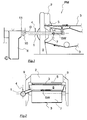
- FIG. 1 the forming area of a paper machine PM is in a greatly simplified form Side view shown.
- a paper machine has, for example, one in the strangulation 9 mounted forming roller 7, on which an endless screen 3 rotates.
- the paper production needed Suspension is through a headbox 2 and a broad jet nozzle 5 from above to the circulating Sieve 3 abandoned.
- this suspension usually has a water content between 98 and 99% has a large amount of white water immediately after the addition of the suspension passes through the sieve. 3 through and is collected as white water SW in the white water tank 8. Even after that Sieve 3 has left the area of the white water tank 8, more white water is removed, which but not of direct interest here.
- the pipeline extends horizontally in its longitudinal direction.
- Length and Cross section of the pipe 1 are advantageously designed so that the residence time between 20 and 30 sec, which experience has shown is sufficient to calm the flow turbulences and pre-degassing leads. In practice this means a typical one Flow rate of about 0.5 m / s, a length of the pipe 1 from 10 to 15 m. That I in the upper part of the pipeline 1 accumulating gas can be through one or more attached above Degassing 4 are removed, will be discussed in more detail.
- the pipeline 1 opens into an open-topped white water tank 6. Das Level 11 of this white water tank 6 can be adjusted so that it is above the pipeline 1 is, e.g. a difference height D of about 100 - 200 mm is useful.
- Another advantage of the method is that with simple means of White water flow rate can be measured early, since already at the end of the pipe 1 the physical prerequisites for such a measurement can be given.
- an inductive flow meter 10 located.
- the paper machine PM shown in FIGS. 1 and 2 is to be understood here only as an example. Of course, paper machines that work with other formers or headboxes are provided, the open-occurring white water in the manner described by the Derive pipeline used in the invention. Although in Figs. 1 and 2, the main direction the pipeline 1 is shown parallel to the wire direction of the paper machine, depending on the available space also made a different arrangement of the pipeline. she can also have one or more deflections.
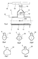
- Fig. 3 the conditions in the vicinity of a patch on the pipe 1 Degassing device 4 shown.
- This figure shows the degassing tube 12, which expediently mounted in the uppermost part of the pipe cross-section of the pipe 1 and here in Operation is partially filled with white water. Therefore, a free forms in this degassing 12 Surface where the gas can escape from the white water.
- a Set phase limit Shown is also the level 11 of the white water tank (or another Counter levels at the outlet of the pipeline 1). The level 11 may be due to the Flow rate in the pipeline 1 from that of the free surface in the degassing tube 12 differ.
- a simplest degassing option arises when the gas passes through it lying connection pipe 13 can enter the environment, resulting in the effect of the beginning mentioned above, without having their disadvantages. But it is mostly expedient, possibly formed foam and the heavily moisture-laden gases, So the steam 16 to suck, with a negative pressure of about 1.5 to 2 bar is appropriate. A such steam extraction 14 is only hinted at here. Perhaps it is appropriate, the free Surface, which forms in the degassing tube 12, with water, in particular white water to spray to avoid build-up of deposits.
- Fig. 3 also shows a way to possible settlements at the bottom of the pipe 1 to prevent.
- Fig. 3 also shows a way to possible settlements at the bottom of the pipe 1 to prevent.
- openings 17 bottom scavenging tube 18 in the lower part of Pipe used. It can be operated with white water under overpressure.
- the typical cross-sectional shape of the pipe 1 (Fig. 2) for carrying out the method is likely to of a circle, which is particularly favorable in terms of production and strength.
- Fig. 4 is an upstanding oval profile 19 and in Fig. 5 a lying oval profile 20 shown.
- a rhombus 21 as shown in Fig. 6, combines a high strength with good flow properties.
- a hexagonal profile 23 as shown in FIG. 8 may be appropriate.
- the in Figs. 6 to 8 Cases shown are for aerodynamic (and manufacturing) reasons, the corners rounded. It is of course conceivable, even more profiles for the pipe 1 to use to perform the procedure optimally.
Landscapes
- Paper (AREA)
- Developing Agents For Electrophotography (AREA)
Abstract
Description
- Fig. 1
- schematisch: Eine Anlage zur Durchführung des erfindungsgemäßen Verfahrens in Seitenansicht;
- Fig. 2
- schematisch: Eine ähnliche Anlage mit Blickrichtung entgegen Sieblaufrichtung auf den Stoffauflauf;
- Fig. 3
- Teil einer erfindungsgemäß verwendeten Rohrleitung mit Entgasungseinrichtung;
- Fig. 4 -8
- je eine Variante der Querschnittsform der Rohrleitung, jeweils in Gebrauchslage dargestellt.
Claims (18)
- Verfahren zum Führen von an einer Papiermaschine (PM) offen anfallendem Siebwasser (SW), das zunächst in der Papiermaschine (PM) gesammelt und dann zur Weiterverarbeitung geleitet wird,
dadurch gekennzeichnet, dass die Weiterleitung in einer geschlossenen Rohrleitung (1) erfolgt, die zur Horizontalen einen Winkel (α) zwischen 0 und 15°, vorzugsweise 0°, hat und dass die mittlere Verweilzeit des Siebwassers (SW) in dieser Rohrleitung (1) mindestens 5 sec, vorzugsweise 20-30 sec, beträgt. - Verfahren nach Anspruch 1,
dadurch gekennzeichnet, dass der Querschnitt der Rohrleitung (1) kreisförmig ist. - Verfahren nach Anspruch 1,
dadurch gekennzeichnet, dass der Querschnitt der Rohrleitung (1) oval ist. - Verfahren nach Anspruch 1,
dadurch gekennzeichnet, dass der Querschnitt der Rohrleitung (1) die Form einer an den Ecken gerundeten Raute (21) mit oben liegender Ecke hat. - Verfahren nach Anspruch 1,
dadurch gekennzeichnet, dass der Querschnitt der Rohrleitung (1) die Form eines an den Ecken gerundeten breiten Sechsecks (22) mit oben liegender Ecke hat. - Verfahren nach Anspruch 1,
dadurch gekennzeichnet, dass der Querschnitt der Rohrleitung (1) die Form eines an den Ecken gerundeten Fünfecks mit oben liegender Ecke hat. - Verfahren nach einem der voranstehenden Ansprüche,
dadurch gekennzeichnet, dass das Siebwasser (SW) das zuerst anfallende Siebwasser der Papiermaschine ist. - Verfahren nach einem der voranstehenden Ansprüche,
dadurch gekennzeichnet, dass das Siebwasser (SW) aus der Rohrleitung (1) in ein Flüssigkeitsvolumen geführt wird mit einer freien Flüssigkeitsoberfläche, an der Atmosphärendruck herrscht. - Verfahren nach Anspruch 8,
dadurch gekennzeichnet, dass das Siebwasser (SW) aus der Rohrleitung (1) in einen oben offenen
Siebwassertank (6) geführt wird. - Verfahren nach einem der voranstehenden Ansprüche,
dadurch gekennzeichnet, dass aus dem Siebwasser (SW) Gas, insbesondere Luft, durch mindestens eine Öffnung in der Wand der Rohrleitung (1) entfernt wird. - Verfahren nach Anspruch 10,
dadurch gekennzeichnet, dass die Rohrleitung (1) mit mindestens einer, vorzugsweise zwei bis drei, oben angesetzten Entgasungseinrichtungen (4, 4') versehen ist. - Verfahren nach Anspruch 10 oder 11 jeweils in Verbindung mit Anspruch 8 oder 9,
dadurch gekennzeichnet, dass das Niveau (11) der Flüssigkeitsoberfläche des Flüssigkeitsvolumens geodätisch oberhalb der inneren Oberkante der Rohrleitung (1) eingestellt wird. - Verfahren nach Anspruch 12,
dadurch gekennzeichnet, dass das Niveau (11) auf maximal 200 mm oberhalb der inneren Oberkante der Rohrleitung eingestellt wird. - Verfahren nach Anspruch 11, 12 oder 13,
dadurch gekennzeichnet, dass die Entgasungseinrichtung (4, 4') unter Unterdruck gesetzt wird. - Verfahren nach Anspruch 14,
dadurch gekennzeichnet, dass der Unterdruck auf 1,5 bis 2 bar eingestellt wird. - Verfahren nach einem der voranstehenden Ansprüche,
dadurch gekennzeichnet, dass in der Rohrleitung (1) der Mengenstrom des Siebwassers (SW) gemessen wird. - Verfahren nach Anspruch 16,
dadurch gekennzeichnet, dass zur Messung ein am Ende der Rohrleitung (1) installierter induktiver Durchflussmesser (10) verwendet wird. - Verfahren nach einem der voranstehenden Ansprüche,
dadurch gekennzeichnet, dass in der Rohrleitung (1) eine mittlere Strömungsgeschwindigkeit des Siebwassers (SW) von maximal 0,8 m/s, vorzugsweise 0,2 bis 0,6 m/s, eingestellt wird.
Applications Claiming Priority (2)
| Application Number | Priority Date | Filing Date | Title |
|---|---|---|---|
| DE10356576A DE10356576A1 (de) | 2003-12-04 | 2003-12-04 | Verfahren zum Führen von an einer Papiermaschine offen anfallendem Siebwasser |
| DE10356576 | 2003-12-04 |
Publications (2)
| Publication Number | Publication Date |
|---|---|
| EP1538258A1 true EP1538258A1 (de) | 2005-06-08 |
| EP1538258B1 EP1538258B1 (de) | 2007-09-26 |
Family
ID=34442431
Family Applications (1)
| Application Number | Title | Priority Date | Filing Date |
|---|---|---|---|
| EP04025257A Expired - Lifetime EP1538258B1 (de) | 2003-12-04 | 2004-10-23 | Verfahren zum Führen von an einer Papiermaschine offen anfallendem Siebwasser |
Country Status (3)
| Country | Link |
|---|---|
| EP (1) | EP1538258B1 (de) |
| AT (1) | ATE374282T1 (de) |
| DE (2) | DE10356576A1 (de) |
Cited By (1)
| Publication number | Priority date | Publication date | Assignee | Title |
|---|---|---|---|---|
| DE102009000803A1 (de) | 2009-02-12 | 2010-08-19 | Voith Patent Gmbh | Doppelsiebformer |
Citations (3)
| Publication number | Priority date | Publication date | Assignee | Title |
|---|---|---|---|---|
| DE19938799A1 (de) * | 1999-08-16 | 2001-02-22 | Voith Sulzer Papiertech Patent | Verfahren zum Führen und Entlüften von an einer Papiermaschine anfallendem Siebwasser |
| WO2001081676A1 (en) * | 2000-04-19 | 2001-11-01 | Pom Technology Oy Ab | A process and an arrangement at suction element |
| WO2001094693A1 (en) * | 2000-06-09 | 2001-12-13 | Metso Paper Karlstad Aktiebolag | Arrangement with white water channel |
Family Cites Families (2)
| Publication number | Priority date | Publication date | Assignee | Title |
|---|---|---|---|---|
| FI97332C (fi) * | 1993-12-23 | 2006-11-24 | Pom Tech Oy Ab | Kaasunerotuspumppu paperinvalmistuksessa virtaavan veden tai nestemäisen kuitususpension ja ilman erottamiseksi toisistaan pumppauksen yhteydessä |
| DE10107328A1 (de) * | 2001-02-16 | 2002-08-29 | Voith Paper Patent Gmbh | Verfahren und Vorrichtung zum Abführen von Siebwasser |
-
2003
- 2003-12-04 DE DE10356576A patent/DE10356576A1/de not_active Withdrawn
-
2004
- 2004-10-23 EP EP04025257A patent/EP1538258B1/de not_active Expired - Lifetime
- 2004-10-23 AT AT04025257T patent/ATE374282T1/de not_active IP Right Cessation
- 2004-10-23 DE DE502004005070T patent/DE502004005070D1/de not_active Expired - Lifetime
Patent Citations (3)
| Publication number | Priority date | Publication date | Assignee | Title |
|---|---|---|---|---|
| DE19938799A1 (de) * | 1999-08-16 | 2001-02-22 | Voith Sulzer Papiertech Patent | Verfahren zum Führen und Entlüften von an einer Papiermaschine anfallendem Siebwasser |
| WO2001081676A1 (en) * | 2000-04-19 | 2001-11-01 | Pom Technology Oy Ab | A process and an arrangement at suction element |
| WO2001094693A1 (en) * | 2000-06-09 | 2001-12-13 | Metso Paper Karlstad Aktiebolag | Arrangement with white water channel |
Cited By (2)
| Publication number | Priority date | Publication date | Assignee | Title |
|---|---|---|---|---|
| DE102009000803A1 (de) | 2009-02-12 | 2010-08-19 | Voith Patent Gmbh | Doppelsiebformer |
| WO2010091915A1 (de) | 2009-02-12 | 2010-08-19 | Voith Patent Gmbh | Doppelsiebformer |
Also Published As
| Publication number | Publication date |
|---|---|
| ATE374282T1 (de) | 2007-10-15 |
| DE10356576A1 (de) | 2005-07-07 |
| DE502004005070D1 (de) | 2007-11-08 |
| EP1538258B1 (de) | 2007-09-26 |
Similar Documents
| Publication | Publication Date | Title |
|---|---|---|
| DE60009500T2 (de) | Schaumverfahren zur papierherstellung mit schaumverdünnung | |
| DE4204991A1 (de) | Verfahren und einrichtung zur beeinflussung von im erdreich befindlicher fluessigkeit | |
| DE2950194C2 (de) | Vorrichtung zum Sammeln einer Flüssigkeit an einem ersten Ort und zum Fördern der Flüssigkeit an einen anderen unterhalb des ersten Orts liegenden zweiten Ort | |
| DE69908351T2 (de) | Vorrichtung zum entgasen einer wässerigen fasersuspension | |
| DE69115020T2 (de) | Vorrichtung zum entfernen von flüssigkeit aus dem innern eines rotierenden zylinders oder einer walze. | |
| EP1538258B1 (de) | Verfahren zum Führen von an einer Papiermaschine offen anfallendem Siebwasser | |
| DE2235847A1 (de) | Verfahren und maschine zum herstellen nicht gewebter faserstoffe aus faserigem material | |
| DE102009027798A1 (de) | Messvorrichtung zur Volumenstrommessung | |
| WO2012038245A1 (de) | Entgasung | |
| DE10107328A1 (de) | Verfahren und Vorrichtung zum Abführen von Siebwasser | |
| DE10131982A1 (de) | Verfahren und Vorrichtung zum Entgasen von Suspension, insbesondere Faserstoffsuspension | |
| DE2753366A1 (de) | Vorrichtung zum trennen von feinteilchen von grobteilchen | |
| DE1951202A1 (de) | Verfahren und Vorrichtung zur Herstellung eines faserigen Bogens,insbesondere eines Papierbogens | |
| DE69023894T2 (de) | Verfahren zur bildung und befreiung von wasser von einem band auf einer fourdriniermaschine. | |
| DE60120464T2 (de) | Vorrichtung und verfahren zum entwässern eines cellulosevlieses | |
| DE1461179A1 (de) | Siebpartie einer Langsiebpapiermaschine mit Blattbildung unter Luftabschluss | |
| DE60009094T2 (de) | Siebwasserkasten | |
| DE602004010139T2 (de) | Verfahren und vorrichtung zur trennung von materialströmen | |
| DE2023521C3 (de) | Siebteil einer Maschine zum Herstellen von Faserstoffbahnen J.M. Voith GmbH, 7920 Heidenheim | |
| EP1953296B1 (de) | Verfahren zur Herstellung einer Faserstoffbahn und Doppelsiebformer zur Durchführung des Verfahrens | |
| DE102010042604A1 (de) | Blattbildungseinheit zur Herstellung einer Materialbahn und Verfahren zum Betreiben der Blattbildungseinheit | |
| DE102022121105A1 (de) | Schrägsiebformer | |
| DE3028428A1 (de) | Siebteil einer maschine zum herstellen einer faserstoffbahn | |
| DE60125358T2 (de) | Vorrichtung für einen siebwasserabführkanal | |
| DE102011087068A1 (de) | Überlauf |
Legal Events
| Date | Code | Title | Description |
|---|---|---|---|
| PUAI | Public reference made under article 153(3) epc to a published international application that has entered the european phase |
Free format text: ORIGINAL CODE: 0009012 |
|
| AK | Designated contracting states |
Kind code of ref document: A1 Designated state(s): AT BE BG CH CY CZ DE DK EE ES FI FR GB GR HU IE IT LI LU MC NL PL PT RO SE SI SK TR |
|
| AX | Request for extension of the european patent |
Extension state: AL HR LT LV MK |
|
| 17P | Request for examination filed |
Effective date: 20051208 |
|
| AKX | Designation fees paid |
Designated state(s): AT BE BG CH CY CZ DE DK EE ES FI FR GB GR HU IE IT LI LU MC NL PL PT RO SE SI SK TR |
|
| RAP1 | Party data changed (applicant data changed or rights of an application transferred) |
Owner name: VOITH PATENT GMBH |
|
| GRAP | Despatch of communication of intention to grant a patent |
Free format text: ORIGINAL CODE: EPIDOSNIGR1 |
|
| GRAS | Grant fee paid |
Free format text: ORIGINAL CODE: EPIDOSNIGR3 |
|
| GRAA | (expected) grant |
Free format text: ORIGINAL CODE: 0009210 |
|
| AK | Designated contracting states |
Kind code of ref document: B1 Designated state(s): AT BE BG CH CY CZ DE DK EE ES FI FR GB GR HU IE IT LI LU MC NL PL PT RO SE SI SK TR |
|
| REG | Reference to a national code |
Ref country code: GB Ref legal event code: FG4D Free format text: NOT ENGLISH |
|
| REG | Reference to a national code |
Ref country code: CH Ref legal event code: EP |
|
| REF | Corresponds to: |
Ref document number: 502004005070 Country of ref document: DE Date of ref document: 20071108 Kind code of ref document: P |
|
| REG | Reference to a national code |
Ref country code: IE Ref legal event code: FG4D Free format text: LANGUAGE OF EP DOCUMENT: GERMAN |
|
| ET | Fr: translation filed | ||
| PG25 | Lapsed in a contracting state [announced via postgrant information from national office to epo] |
Ref country code: PL Free format text: LAPSE BECAUSE OF FAILURE TO SUBMIT A TRANSLATION OF THE DESCRIPTION OR TO PAY THE FEE WITHIN THE PRESCRIBED TIME-LIMIT Effective date: 20070926 |
|
| NLV1 | Nl: lapsed or annulled due to failure to fulfill the requirements of art. 29p and 29m of the patents act | ||
| GBV | Gb: ep patent (uk) treated as always having been void in accordance with gb section 77(7)/1977 [no translation filed] | ||
| BERE | Be: lapsed |
Owner name: VOITH PATENT G.M.B.H. Effective date: 20071031 |
|
| PG25 | Lapsed in a contracting state [announced via postgrant information from national office to epo] |
Ref country code: GR Free format text: LAPSE BECAUSE OF FAILURE TO SUBMIT A TRANSLATION OF THE DESCRIPTION OR TO PAY THE FEE WITHIN THE PRESCRIBED TIME-LIMIT Effective date: 20071227 Ref country code: NL Free format text: LAPSE BECAUSE OF FAILURE TO SUBMIT A TRANSLATION OF THE DESCRIPTION OR TO PAY THE FEE WITHIN THE PRESCRIBED TIME-LIMIT Effective date: 20070926 Ref country code: ES Free format text: LAPSE BECAUSE OF FAILURE TO SUBMIT A TRANSLATION OF THE DESCRIPTION OR TO PAY THE FEE WITHIN THE PRESCRIBED TIME-LIMIT Effective date: 20080106 |
|
| REG | Reference to a national code |
Ref country code: IE Ref legal event code: FD4D |
|
| PG25 | Lapsed in a contracting state [announced via postgrant information from national office to epo] |
Ref country code: PT Free format text: LAPSE BECAUSE OF FAILURE TO SUBMIT A TRANSLATION OF THE DESCRIPTION OR TO PAY THE FEE WITHIN THE PRESCRIBED TIME-LIMIT Effective date: 20080226 Ref country code: MC Free format text: LAPSE BECAUSE OF NON-PAYMENT OF DUE FEES Effective date: 20071031 Ref country code: SK Free format text: LAPSE BECAUSE OF FAILURE TO SUBMIT A TRANSLATION OF THE DESCRIPTION OR TO PAY THE FEE WITHIN THE PRESCRIBED TIME-LIMIT Effective date: 20070926 Ref country code: CZ Free format text: LAPSE BECAUSE OF FAILURE TO SUBMIT A TRANSLATION OF THE DESCRIPTION OR TO PAY THE FEE WITHIN THE PRESCRIBED TIME-LIMIT Effective date: 20070926 |
|
| PG25 | Lapsed in a contracting state [announced via postgrant information from national office to epo] |
Ref country code: RO Free format text: LAPSE BECAUSE OF FAILURE TO SUBMIT A TRANSLATION OF THE DESCRIPTION OR TO PAY THE FEE WITHIN THE PRESCRIBED TIME-LIMIT Effective date: 20070926 Ref country code: SE Free format text: LAPSE BECAUSE OF FAILURE TO SUBMIT A TRANSLATION OF THE DESCRIPTION OR TO PAY THE FEE WITHIN THE PRESCRIBED TIME-LIMIT Effective date: 20071226 |
|
| PG25 | Lapsed in a contracting state [announced via postgrant information from national office to epo] |
Ref country code: DK Free format text: LAPSE BECAUSE OF FAILURE TO SUBMIT A TRANSLATION OF THE DESCRIPTION OR TO PAY THE FEE WITHIN THE PRESCRIBED TIME-LIMIT Effective date: 20070926 |
|
| PLBE | No opposition filed within time limit |
Free format text: ORIGINAL CODE: 0009261 |
|
| STAA | Information on the status of an ep patent application or granted ep patent |
Free format text: STATUS: NO OPPOSITION FILED WITHIN TIME LIMIT |
|
| 26N | No opposition filed |
Effective date: 20080627 |
|
| PG25 | Lapsed in a contracting state [announced via postgrant information from national office to epo] |
Ref country code: BE Free format text: LAPSE BECAUSE OF NON-PAYMENT OF DUE FEES Effective date: 20071031 |
|
| PG25 | Lapsed in a contracting state [announced via postgrant information from national office to epo] |
Ref country code: IE Free format text: LAPSE BECAUSE OF FAILURE TO SUBMIT A TRANSLATION OF THE DESCRIPTION OR TO PAY THE FEE WITHIN THE PRESCRIBED TIME-LIMIT Effective date: 20070926 |
|
| PG25 | Lapsed in a contracting state [announced via postgrant information from national office to epo] |
Ref country code: GB Free format text: LAPSE BECAUSE OF FAILURE TO SUBMIT A TRANSLATION OF THE DESCRIPTION OR TO PAY THE FEE WITHIN THE PRESCRIBED TIME-LIMIT Effective date: 20070926 |
|
| PG25 | Lapsed in a contracting state [announced via postgrant information from national office to epo] |
Ref country code: EE Free format text: LAPSE BECAUSE OF FAILURE TO SUBMIT A TRANSLATION OF THE DESCRIPTION OR TO PAY THE FEE WITHIN THE PRESCRIBED TIME-LIMIT Effective date: 20070926 |
|
| REG | Reference to a national code |
Ref country code: CH Ref legal event code: PL |
|
| PG25 | Lapsed in a contracting state [announced via postgrant information from national office to epo] |
Ref country code: SI Free format text: LAPSE BECAUSE OF FAILURE TO SUBMIT A TRANSLATION OF THE DESCRIPTION OR TO PAY THE FEE WITHIN THE PRESCRIBED TIME-LIMIT Effective date: 20070926 |
|
| PG25 | Lapsed in a contracting state [announced via postgrant information from national office to epo] |
Ref country code: CY Free format text: LAPSE BECAUSE OF FAILURE TO SUBMIT A TRANSLATION OF THE DESCRIPTION OR TO PAY THE FEE WITHIN THE PRESCRIBED TIME-LIMIT Effective date: 20070926 |
|
| PG25 | Lapsed in a contracting state [announced via postgrant information from national office to epo] |
Ref country code: BG Free format text: LAPSE BECAUSE OF FAILURE TO SUBMIT A TRANSLATION OF THE DESCRIPTION OR TO PAY THE FEE WITHIN THE PRESCRIBED TIME-LIMIT Effective date: 20071226 Ref country code: LU Free format text: LAPSE BECAUSE OF NON-PAYMENT OF DUE FEES Effective date: 20071023 |
|
| PG25 | Lapsed in a contracting state [announced via postgrant information from national office to epo] |
Ref country code: TR Free format text: LAPSE BECAUSE OF FAILURE TO SUBMIT A TRANSLATION OF THE DESCRIPTION OR TO PAY THE FEE WITHIN THE PRESCRIBED TIME-LIMIT Effective date: 20070926 Ref country code: HU Free format text: LAPSE BECAUSE OF FAILURE TO SUBMIT A TRANSLATION OF THE DESCRIPTION OR TO PAY THE FEE WITHIN THE PRESCRIBED TIME-LIMIT Effective date: 20080327 |
|
| PG25 | Lapsed in a contracting state [announced via postgrant information from national office to epo] |
Ref country code: LI Free format text: LAPSE BECAUSE OF NON-PAYMENT OF DUE FEES Effective date: 20081031 Ref country code: CH Free format text: LAPSE BECAUSE OF NON-PAYMENT OF DUE FEES Effective date: 20081031 |
|
| PGFP | Annual fee paid to national office [announced via postgrant information from national office to epo] |
Ref country code: AT Payment date: 20091015 Year of fee payment: 6 Ref country code: DE Payment date: 20091026 Year of fee payment: 6 Ref country code: FI Payment date: 20091015 Year of fee payment: 6 |
|
| PGFP | Annual fee paid to national office [announced via postgrant information from national office to epo] |
Ref country code: FR Payment date: 20091110 Year of fee payment: 6 |
|
| PG25 | Lapsed in a contracting state [announced via postgrant information from national office to epo] |
Ref country code: IT Free format text: LAPSE BECAUSE OF NON-PAYMENT OF DUE FEES Effective date: 20071031 |
|
| PG25 | Lapsed in a contracting state [announced via postgrant information from national office to epo] |
Ref country code: FR Free format text: LAPSE BECAUSE OF NON-PAYMENT OF DUE FEES Effective date: 20101102 |
|
| REG | Reference to a national code |
Ref country code: FR Ref legal event code: ST Effective date: 20110630 |
|
| PG25 | Lapsed in a contracting state [announced via postgrant information from national office to epo] |
Ref country code: FI Free format text: LAPSE BECAUSE OF NON-PAYMENT OF DUE FEES Effective date: 20101023 Ref country code: AT Free format text: LAPSE BECAUSE OF NON-PAYMENT OF DUE FEES Effective date: 20101023 |
|
| REG | Reference to a national code |
Ref country code: DE Ref legal event code: R119 Ref document number: 502004005070 Country of ref document: DE Effective date: 20110502 |
|
| PG25 | Lapsed in a contracting state [announced via postgrant information from national office to epo] |
Ref country code: DE Free format text: LAPSE BECAUSE OF NON-PAYMENT OF DUE FEES Effective date: 20110502 |