EP1538013A2 - Steuerung für eines motorisierten Fahrzeug mit Vierradantrieb und Steuerungsverfahren - Google Patents
Steuerung für eines motorisierten Fahrzeug mit Vierradantrieb und Steuerungsverfahren Download PDFInfo
- Publication number
- EP1538013A2 EP1538013A2 EP04028160A EP04028160A EP1538013A2 EP 1538013 A2 EP1538013 A2 EP 1538013A2 EP 04028160 A EP04028160 A EP 04028160A EP 04028160 A EP04028160 A EP 04028160A EP 1538013 A2 EP1538013 A2 EP 1538013A2
- Authority
- EP
- European Patent Office
- Prior art keywords
- motor
- electric power
- power
- driven
- rated voltage
- Prior art date
- Legal status (The legal status is an assumption and is not a legal conclusion. Google has not performed a legal analysis and makes no representation as to the accuracy of the status listed.)
- Withdrawn
Links
Images


Classifications
-
- B—PERFORMING OPERATIONS; TRANSPORTING
- B60—VEHICLES IN GENERAL
- B60W—CONJOINT CONTROL OF VEHICLE SUB-UNITS OF DIFFERENT TYPE OR DIFFERENT FUNCTION; CONTROL SYSTEMS SPECIALLY ADAPTED FOR HYBRID VEHICLES; ROAD VEHICLE DRIVE CONTROL SYSTEMS FOR PURPOSES NOT RELATED TO THE CONTROL OF A PARTICULAR SUB-UNIT
- B60W20/00—Control systems specially adapted for hybrid vehicles
- B60W20/10—Controlling the power contribution of each of the prime movers to meet required power demand
-
- B—PERFORMING OPERATIONS; TRANSPORTING
- B60—VEHICLES IN GENERAL
- B60K—ARRANGEMENT OR MOUNTING OF PROPULSION UNITS OR OF TRANSMISSIONS IN VEHICLES; ARRANGEMENT OR MOUNTING OF PLURAL DIVERSE PRIME-MOVERS IN VEHICLES; AUXILIARY DRIVES FOR VEHICLES; INSTRUMENTATION OR DASHBOARDS FOR VEHICLES; ARRANGEMENTS IN CONNECTION WITH COOLING, AIR INTAKE, GAS EXHAUST OR FUEL SUPPLY OF PROPULSION UNITS IN VEHICLES
- B60K6/00—Arrangement or mounting of plural diverse prime-movers for mutual or common propulsion, e.g. hybrid propulsion systems comprising electric motors and internal combustion engines
- B60K6/20—Arrangement or mounting of plural diverse prime-movers for mutual or common propulsion, e.g. hybrid propulsion systems comprising electric motors and internal combustion engines the prime-movers consisting of electric motors and internal combustion engines, e.g. HEVs
- B60K6/22—Arrangement or mounting of plural diverse prime-movers for mutual or common propulsion, e.g. hybrid propulsion systems comprising electric motors and internal combustion engines the prime-movers consisting of electric motors and internal combustion engines, e.g. HEVs characterised by apparatus, components or means specially adapted for HEVs
- B60K6/28—Arrangement or mounting of plural diverse prime-movers for mutual or common propulsion, e.g. hybrid propulsion systems comprising electric motors and internal combustion engines the prime-movers consisting of electric motors and internal combustion engines, e.g. HEVs characterised by apparatus, components or means specially adapted for HEVs characterised by the electric energy storing means, e.g. batteries or capacitors
-
- B—PERFORMING OPERATIONS; TRANSPORTING
- B60—VEHICLES IN GENERAL
- B60K—ARRANGEMENT OR MOUNTING OF PROPULSION UNITS OR OF TRANSMISSIONS IN VEHICLES; ARRANGEMENT OR MOUNTING OF PLURAL DIVERSE PRIME-MOVERS IN VEHICLES; AUXILIARY DRIVES FOR VEHICLES; INSTRUMENTATION OR DASHBOARDS FOR VEHICLES; ARRANGEMENTS IN CONNECTION WITH COOLING, AIR INTAKE, GAS EXHAUST OR FUEL SUPPLY OF PROPULSION UNITS IN VEHICLES
- B60K17/00—Arrangement or mounting of transmissions in vehicles
- B60K17/34—Arrangement or mounting of transmissions in vehicles for driving both front and rear wheels, e.g. four wheel drive vehicles
- B60K17/356—Arrangement or mounting of transmissions in vehicles for driving both front and rear wheels, e.g. four wheel drive vehicles having fluid or electric motor, for driving one or more wheels
-
- B—PERFORMING OPERATIONS; TRANSPORTING
- B60—VEHICLES IN GENERAL
- B60K—ARRANGEMENT OR MOUNTING OF PROPULSION UNITS OR OF TRANSMISSIONS IN VEHICLES; ARRANGEMENT OR MOUNTING OF PLURAL DIVERSE PRIME-MOVERS IN VEHICLES; AUXILIARY DRIVES FOR VEHICLES; INSTRUMENTATION OR DASHBOARDS FOR VEHICLES; ARRANGEMENTS IN CONNECTION WITH COOLING, AIR INTAKE, GAS EXHAUST OR FUEL SUPPLY OF PROPULSION UNITS IN VEHICLES
- B60K6/00—Arrangement or mounting of plural diverse prime-movers for mutual or common propulsion, e.g. hybrid propulsion systems comprising electric motors and internal combustion engines
- B60K6/20—Arrangement or mounting of plural diverse prime-movers for mutual or common propulsion, e.g. hybrid propulsion systems comprising electric motors and internal combustion engines the prime-movers consisting of electric motors and internal combustion engines, e.g. HEVs
- B60K6/50—Architecture of the driveline characterised by arrangement or kind of transmission units
- B60K6/52—Driving a plurality of drive axles, e.g. four-wheel drive
-
- B—PERFORMING OPERATIONS; TRANSPORTING
- B60—VEHICLES IN GENERAL
- B60L—PROPULSION OF ELECTRICALLY-PROPELLED VEHICLES; SUPPLYING ELECTRIC POWER FOR AUXILIARY EQUIPMENT OF ELECTRICALLY-PROPELLED VEHICLES; ELECTRODYNAMIC BRAKE SYSTEMS FOR VEHICLES IN GENERAL; MAGNETIC SUSPENSION OR LEVITATION FOR VEHICLES; MONITORING OPERATING VARIABLES OF ELECTRICALLY-PROPELLED VEHICLES; ELECTRIC SAFETY DEVICES FOR ELECTRICALLY-PROPELLED VEHICLES
- B60L50/00—Electric propulsion with power supplied within the vehicle
- B60L50/10—Electric propulsion with power supplied within the vehicle using propulsion power supplied by engine-driven generators, e.g. generators driven by combustion engines
- B60L50/12—Electric propulsion with power supplied within the vehicle using propulsion power supplied by engine-driven generators, e.g. generators driven by combustion engines using AC generators and DC motors
-
- B—PERFORMING OPERATIONS; TRANSPORTING
- B60—VEHICLES IN GENERAL
- B60L—PROPULSION OF ELECTRICALLY-PROPELLED VEHICLES; SUPPLYING ELECTRIC POWER FOR AUXILIARY EQUIPMENT OF ELECTRICALLY-PROPELLED VEHICLES; ELECTRODYNAMIC BRAKE SYSTEMS FOR VEHICLES IN GENERAL; MAGNETIC SUSPENSION OR LEVITATION FOR VEHICLES; MONITORING OPERATING VARIABLES OF ELECTRICALLY-PROPELLED VEHICLES; ELECTRIC SAFETY DEVICES FOR ELECTRICALLY-PROPELLED VEHICLES
- B60L50/00—Electric propulsion with power supplied within the vehicle
- B60L50/10—Electric propulsion with power supplied within the vehicle using propulsion power supplied by engine-driven generators, e.g. generators driven by combustion engines
- B60L50/16—Electric propulsion with power supplied within the vehicle using propulsion power supplied by engine-driven generators, e.g. generators driven by combustion engines with provision for separate direct mechanical propulsion
-
- B—PERFORMING OPERATIONS; TRANSPORTING
- B60—VEHICLES IN GENERAL
- B60W—CONJOINT CONTROL OF VEHICLE SUB-UNITS OF DIFFERENT TYPE OR DIFFERENT FUNCTION; CONTROL SYSTEMS SPECIALLY ADAPTED FOR HYBRID VEHICLES; ROAD VEHICLE DRIVE CONTROL SYSTEMS FOR PURPOSES NOT RELATED TO THE CONTROL OF A PARTICULAR SUB-UNIT
- B60W10/00—Conjoint control of vehicle sub-units of different type or different function
- B60W10/04—Conjoint control of vehicle sub-units of different type or different function including control of propulsion units
- B60W10/06—Conjoint control of vehicle sub-units of different type or different function including control of propulsion units including control of combustion engines
-
- B—PERFORMING OPERATIONS; TRANSPORTING
- B60—VEHICLES IN GENERAL
- B60W—CONJOINT CONTROL OF VEHICLE SUB-UNITS OF DIFFERENT TYPE OR DIFFERENT FUNCTION; CONTROL SYSTEMS SPECIALLY ADAPTED FOR HYBRID VEHICLES; ROAD VEHICLE DRIVE CONTROL SYSTEMS FOR PURPOSES NOT RELATED TO THE CONTROL OF A PARTICULAR SUB-UNIT
- B60W10/00—Conjoint control of vehicle sub-units of different type or different function
- B60W10/24—Conjoint control of vehicle sub-units of different type or different function including control of energy storage means
- B60W10/26—Conjoint control of vehicle sub-units of different type or different function including control of energy storage means for electrical energy, e.g. batteries or capacitors
-
- B—PERFORMING OPERATIONS; TRANSPORTING
- B60—VEHICLES IN GENERAL
- B60W—CONJOINT CONTROL OF VEHICLE SUB-UNITS OF DIFFERENT TYPE OR DIFFERENT FUNCTION; CONTROL SYSTEMS SPECIALLY ADAPTED FOR HYBRID VEHICLES; ROAD VEHICLE DRIVE CONTROL SYSTEMS FOR PURPOSES NOT RELATED TO THE CONTROL OF A PARTICULAR SUB-UNIT
- B60W20/00—Control systems specially adapted for hybrid vehicles
-
- Y—GENERAL TAGGING OF NEW TECHNOLOGICAL DEVELOPMENTS; GENERAL TAGGING OF CROSS-SECTIONAL TECHNOLOGIES SPANNING OVER SEVERAL SECTIONS OF THE IPC; TECHNICAL SUBJECTS COVERED BY FORMER USPC CROSS-REFERENCE ART COLLECTIONS [XRACs] AND DIGESTS
- Y02—TECHNOLOGIES OR APPLICATIONS FOR MITIGATION OR ADAPTATION AGAINST CLIMATE CHANGE
- Y02T—CLIMATE CHANGE MITIGATION TECHNOLOGIES RELATED TO TRANSPORTATION
- Y02T10/00—Road transport of goods or passengers
- Y02T10/60—Other road transportation technologies with climate change mitigation effect
- Y02T10/62—Hybrid vehicles
-
- Y—GENERAL TAGGING OF NEW TECHNOLOGICAL DEVELOPMENTS; GENERAL TAGGING OF CROSS-SECTIONAL TECHNOLOGIES SPANNING OVER SEVERAL SECTIONS OF THE IPC; TECHNICAL SUBJECTS COVERED BY FORMER USPC CROSS-REFERENCE ART COLLECTIONS [XRACs] AND DIGESTS
- Y02—TECHNOLOGIES OR APPLICATIONS FOR MITIGATION OR ADAPTATION AGAINST CLIMATE CHANGE
- Y02T—CLIMATE CHANGE MITIGATION TECHNOLOGIES RELATED TO TRANSPORTATION
- Y02T10/00—Road transport of goods or passengers
- Y02T10/60—Other road transportation technologies with climate change mitigation effect
- Y02T10/70—Energy storage systems for electromobility, e.g. batteries
-
- Y—GENERAL TAGGING OF NEW TECHNOLOGICAL DEVELOPMENTS; GENERAL TAGGING OF CROSS-SECTIONAL TECHNOLOGIES SPANNING OVER SEVERAL SECTIONS OF THE IPC; TECHNICAL SUBJECTS COVERED BY FORMER USPC CROSS-REFERENCE ART COLLECTIONS [XRACs] AND DIGESTS
- Y02—TECHNOLOGIES OR APPLICATIONS FOR MITIGATION OR ADAPTATION AGAINST CLIMATE CHANGE
- Y02T—CLIMATE CHANGE MITIGATION TECHNOLOGIES RELATED TO TRANSPORTATION
- Y02T10/00—Road transport of goods or passengers
- Y02T10/60—Other road transportation technologies with climate change mitigation effect
- Y02T10/7072—Electromobility specific charging systems or methods for batteries, ultracapacitors, supercapacitors or double-layer capacitors
-
- Y—GENERAL TAGGING OF NEW TECHNOLOGICAL DEVELOPMENTS; GENERAL TAGGING OF CROSS-SECTIONAL TECHNOLOGIES SPANNING OVER SEVERAL SECTIONS OF THE IPC; TECHNICAL SUBJECTS COVERED BY FORMER USPC CROSS-REFERENCE ART COLLECTIONS [XRACs] AND DIGESTS
- Y02—TECHNOLOGIES OR APPLICATIONS FOR MITIGATION OR ADAPTATION AGAINST CLIMATE CHANGE
- Y02T—CLIMATE CHANGE MITIGATION TECHNOLOGIES RELATED TO TRANSPORTATION
- Y02T10/00—Road transport of goods or passengers
- Y02T10/60—Other road transportation technologies with climate change mitigation effect
- Y02T10/72—Electric energy management in electromobility
Definitions
- the present invention relates to a control device and related control method for a motor-driven 4WD vehicle wherein either of front wheels and rear wheels are available to be driven by an engine and the others are available to be driven by a motor.
- 4WD vehicles have heretofore been known wherein front wheels are driven with a drive power, generated by an engine, by which an electric power generator is driven to generate electric power which in turn rotationally drives a motor to provide a drive power by which rear wheels are driven (see Japanese Patent Laid Open Publication Nos. 2002-152911 and 2002-200932).
- the present invention has been made to address the above issues encountered in the related art and has an object to provide a control device and control method, for a motor-driven 4WD vehicle, which are able to simplify a device structure.
- one aspect of the present invention provides a control device for a motor-driven 4WD vehicle wherein either one of front wheels or rear wheels are driven by an engine and the others are driven by a motor depending upon needs, comprising: a motor-generator driven by the engine to generate first electric power with a first rated voltage; a set-up and set-down inverter setting down the first electric power to second electric power with a second rated voltage lower than the first rated voltage; and an electrical equipment supplied with the second electric power outputted from the set-up and set-down inverter, wherein the motor is driven with the first electric power outputted from the motor-generator.
- another aspect of the present invention provides a method of controlling a motor-driven 4WD vehicle wherein either one of front wheels or rear wheels are driven by an engine and the others are driven by a motor depending upon needs, the method comprising: causing a set-up and set-down inverter to rectify and set down first electric power with a first rated voltage generated by a motor-generator to second electric power with a second rated voltage lower than the first rated voltage for supplying the second electric power to an electric equipment mounted on a vehicle; and causing the set-up and set-down inverter to set up third electric power with a third rated voltage generated by the electric equipment to fourth electric power with a fourth rated voltage higher than the third rated voltage and convert to the fourth electric power to fifth electric power with a fifth rated voltage thereby supplying the fifth electric power to the motor so that performing 4WD drive.
- a control device of a first embodiments serves to control a vehicle with a structure wherein either of the front wheels or rear wheels are driven with an engine and the others are driven with a motor.
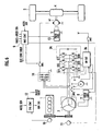
- the vehicle is comprised of an engine 1, a 42V alternator (motor-generator) (ALT) 2 connected to the engine 1 through a belt to transmit rotational power of the engine 1 to generate AC power (e.g., three-phase AC power) at 42V (a first rated voltage) and operative to serve as an electric motor during engine start-up, a diode bridge circuit 14 (rectifying means) that rectifies AC power generated by the 42V alternator 2, a set-up and set-down inverter 3, and a 14V battery (electrical equipment) (BAT) E1 that supplies driving electric power to a variety of instrumented equipments installed on a vehicle.
- AC power e.g., three-phase AC power
- 42V a first rated voltage
- BAT 14V battery (electrical equipment)
- the vehicle is comprised of a DC motor (MOT) M1 that is supplied with DC power, rectified by the diode bridge circuit 14, to be rotationally driven, a differential gear 4 connected to an output shaft of the motor M1, and rear wheels 5 rotationally driven with drive power of the motor M1.
- MOT DC motor
- the presently filed embodiment will be described below with reference to an exemplary case where the engine 1 drives the front wheels whereas the motor M1 drives the rear wheels, it will be appreciated that if the engine 1 drives the rear wheels, the motor M1 comes to drive the front wheels.
- control device is comprised of an engine controller (ENG CONT) 12 that controls driving conditions of the engine 1, an engine speed sensor 10 that detects rotational speed of the engine 1, a field control section (FIELD CONT) 8 for controlling electric current flowing across a field winding of the motor M1, a position sensor 11 for detecting a rotator position of the 42V alternator 2, a field control section (FIELD CONT) 13 that controls field current flowing across the field winding of the motor M1, and a voltage sensor 7 for detecting a charging voltage of the 14V battery E1.
- ENG CONT engine controller
- FID CONT field control section
- the set-up and set-down inverter 3 includes an inverter section 3a composed of switching elements Q3 to Q8 such as six pieces of IGBTs or MOS-FETs, and a converter section 3b composed of switching elements Q1, Q2 and a coil L1.
- the inverter section 3a converts three-phase AC power (first electric power with a first rated voltage) (Maximum power: approximately 4kW, Voltage: 11Vrms to 42Vrms), generated by the 42V alternator 2, to DC power and converts DC power (third electric power with a third rated voltage)(Maximum power: approximately 1kW, Voltage: 14V), outputted from the converter section 3b, to three-phase AC power (fourth electric power with a fourth rated voltage) (Maximum power: approximately 1kW, Voltage: 20Vrms) that is supplied to the 42V alternator 2 for rotationally driving the same.
- the converter section 3b sets down the 42V DC power, outputted from the inverter section 3a, to 14V DC power (second electric power with a second rated voltage) (Maximum power: approximately 1kW, Voltage: 14V) that is supplied to the 14V battery E1 for charging the same and sets up 14V DC power (the third electric power), outputted from the 14V battery E1, to 42V DC power to allow resulting set-up DC power to be supplied to the inverter section 3a.
- 14V DC power second electric power with a second rated voltage
- 14V DC power the third electric power
- a 4WD controller (4WD CONT) 9 that when the occurrence of slippage of the wheels is detected, controls 4WD drive in response to a detection signal of an accelerator sensor (ACCEL SENS) (not shown), which detects the amount of displacement of an accelerator pedal (not shown) installed on the vehicle, and a detection signal of a wheel-speed sensor (not shown).
- ACCEL SENS accelerator sensor
- the 4WD controller 9 outputs control signals to field control sections 8, 13 and outputs a command signal for closing a switch SW1 connected between the diode bridge circuit 14 and the motor M1.
- control device includes an inverter driver circuit (INV DR CKT) 6 that outputs ON/OFF signals to control input terminals of the respective switching elements Q3 to Q8 of the set-up and set-down inverter 3 in response to a detection signal of an accelerator switch (ACCEL SWITCH) SW2, which is turned on when the amount of displacement of the accelerator pedal detected by the accelerator sensor exceeds a given value (when a given condition is satisfied), and a rotor position signal of the 42V alternator detected by the position sensor 11, and a converter driver circuit (CONV DR CKT) 15 that outputs ON/OFF signals to control input terminals of the respective switching elements Q1, Q2 of the set-up and set-down inverter 3 in response to the detection signal of the accelerator switch SW2, the detection signal delivered from the position sensor 11 and the detection signal delivered from the voltage sensor 7.
- IVS DR CKT inverter driver circuit
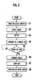
- step 1 If the accelerator switch SW2 is turned on (step 1), under control of the inverter control circuit 6, a field command signal is applied to the field control section 8 to excite the field winding of the 42V alternator 2, rendering the alternator operative as the electric motor (step 2).
- the converter section 3b of the set-up and set-down inverter 3 is supplied with 14V DC power (the third electric power) discharged from the 14V battery E1 and under control of the converter driver circuit 15, the respective switching elements Q1, Q2 are controllably turned on or turned off. This allows 14V DC power (the third electric power) to be set up to 42V DC power that is outputted to the inverter section 3a (step 3).
- the respective switching elements Q3 to Q8 of the inverter section 3a are controllably turned on or turned off in synchronism with the detection signal delivered from the position sensor 11, thereby converting 42V DC power to three-phase 42V AC power (the fourth electric power) (step 4). Then, this three-phase AC power (the fourth electric power) is applied to the 42V alternator 2, which in turn is rotationally driven as the electric motor to rotationally drive the engine 1 connected to the alternator.
- the engine controller 12 allows fuel injections in synchronism with rotation of the engine 1 while initiating ignitions to start up the engine 1.
- step 5 the field control section 13 controls field current to weaken the degree of excitation of the field winding of the 42v alternator 2 (step 6) and, thereafter, the operation of the inverter section 3a of the set-up and set-down inverter 3 is stopped (step 7). In step 8 concurrent with step 7, the operation of the converter section 3b is stopped.
- the start-up operation of the engine 1 can be accomplished in phase with the occurrence of the accelerator switch S2 being turned on. Meanwhile, as shown in FIG.5, during the operation (I) is operated, the battery E1 is discharged (DISCH), the set-up and set-down inverter 3 is operated in a power running mode (PWR), and the 42V alternator (ALT) 2 performs as a motor-generator (MOT).
- DISCH battery E1
- PWR power running mode
- ALT 42V alternator
- MOT motor-generator
- the 4WD controller 9 is responsive to the detection signal of the accelerator sensor and the detection signal of the vehicle-wheel speed sensor to discriminate to find whether 4WD drive is available to be executed under a current status, that is, whether the motor M1 is available to be rotationally driven under the current status (step 11). If discrimination is made that 4WD drive is available, then, the operation proceeds to steps shown in FIG. 4.
- a charged voltage of the 14V battery E1 is detected in response to the output signal of the voltage sensor 7 (step 12).
- the field control section 8 controls field current flowing across the field winding of the 42V alternator 2 in response to the detection signal of the voltage sensor 7 so as to cause the 42V alternator 2 to generate electric power, and resulting three-phase AC power (the first electric power) is supplied to the inverter section 3a of the set-up and set-down inverter 3 by which three-phase AC power, which is generated, is rectified into 42V DC power (step 13).
- the converter driver circuit 15 controllably turns on or turns off the respective switching elements Q1, Q2 of the converter section 3b, thereby converting 42V DC power to 14V DC power (the second electric power) (step 14).
- DC power set down to 14 volts, allows the 14V battery E1 to be charged (step 15).
- the 14V battery E1 is charged at an appropriate voltage in response to the detection signal of the voltage sensor 7.
- the 42V alternator 2 is excited at a level lower than a fully excited condition.
- the 42V alternator 2 uses three-phase AC power (the first electric power) generated by the 42V alternator 2 enables the battery E1 to be charged. Also, field current of the 42V alternator 2 is controlled in response to the detection signal of the voltage sensor 7 to control an output voltage of the 42V alternator 2, enabling reduction in power loss of the converter section 3b. Meanwhile, as shown in FIG.5, during the operation (II) is operated, the set-up and set-down inverter 3 is operated in a regenerative mode (REGEN), and the 42V alternator 2 performs as an alternator (ALT).
- REGEN regenerative mode
- the 4WD controller 9 If discrimination is made by the 4WD controller 9 in response to the detection signals delivered from the accelerator sensor and the vehicle-wheel sensor that 4WD drive needs to be executed (step 21), the 4WD controller 9 outputs a control command to the field control section 8 by which the field winding is fully excited to allow the 42V alternator 2 to provide the maximum power output (step 22). Then, the switch SW1 is turned on and the diode bridge circuit 14 and the motor M1 is brought into electrical connection (step 23).
- the 4WD controller 9 outputs a control command signal to the field control section 13 to excite the field winding of the motor M1 to render the same operative to be rotationally driven (step 24).
- step 25 if it is confirmed in response to the detection signal delivered from the voltage sensor 7 that the 14V battery E1 drops below a given charged voltage (step 25), three-phase AC power (the first electric power) resulting from the 42V alternator 2 is rectified by the inverter section 3a of the set-up and set-down inverter 3 (step 26) to allow DC power (the second electric power) to be supplied to the 14V battery E1 for charging the same.
- DC power the second electric power
- the use of electric power (the first electric power) generated by the 42V alternator 2 provides DC power (the second electric power) for charging the 14V battery E1 and electric power (the fifth electric power) for driving the motor M1, and no need arises for providing separate electric power generators for charging the battery and for driving the motor, enabling a device structure to be simplified. This enables improvement over a freedom in layout while enabling reduction in weight and costs.
- the use of only one motor-generator for supplying electric power to both a motor, to which electric power of a first rated voltage is supplied to be driven, and an electrical equipment to which electric power of a second rated voltage is supplied to be activated enables the device structure to be simplified while providing improvement over a freedom in layout and enabling reduction in weight and costs.
- the accelerator switch SW2 turned on, the engine 1 is started up and an idle-stop mode can be realized, enabling improvement over fuel consumption.
- an idle-stop mode can be realized. Additionally, with the idle-stop mode, the engine automatically stops when the car is stop, hence the fuel consumption can be improved.
- the 14V battery E1 can be supplied with charging power at all times when needed, enabling the 14V battery E1 to be kept at an appropriate charging voltage.
- DC power for driving the motor M1 can be obtained without a need for complicated control, enabling to achieve simplified control operations. Also, with control operation simplified, erroneous operations can be reduced, enabling improvement over reliability in a motor-drive mode.
- the rectifying means rectifies three-phase AC power, generated from the motor-generator (alternator), into DC power that is utilized to rotationally drive the DC motor for 4WD drive, DC power can be obtained without a need for complicated control, enabling control operations to be simplified.
- the field control section 8 controls such that the 42V alternator 2 has a weakened field for thereby causing a drop in power output of the 42V alternator 2, enabling reduction in energy loss of the converter section 3b.
- the output voltage generated by the motor-generator is controlled so as to lie at a voltage lower than that of the maximum power output, enabling reduction in energy loss of the set-up and set-down inverter.
- a control device of the second embodiment is comprised of the engine 1, the 42V alternator (ALT) 2, a set-up and set-down inverter 3A, the diode bridge circuit 14, the motor M1 driven with DC power, a driver circuit (DR CKT) 16, the 14V battery E1 and the voltage sensor 7.
- control device is comprised of the engine speed sensor 10 that detects rotational speed of the engine 1, the position sensor 11 for detecting the rotator position of the 42V alternator 2, the engine controller (ENG CONT) 12 for controlling the engine 1, the 4WD controller (4WD CONT) 9 that controls 4WD drive, the field control section 8 for controlling field current flowing across the field winding of the motor M1, and the field control section (FIELD CONT) 13 that controls field current flowing across the field winding of the motor M1.
- ENG CONT engine controller
- 4WD CONT 4WD CONT
- FED CONT field control section
- a negative terminal of the 14V battery E1 is connected to a negative output terminal of the set-up and set-down inverter 3A and a positive terminal of the 14V battery E1 is connected to a neutral point of the 42V alternator 2 through a switch (switch means) SW3.
- the set-up and set-down inverter 3A includes switching elements Q11 to Q16, such as IGBTs or MOS-FETs, which are controllably turned on or turned off for rectifying three-phase AC power (the first electric power with the first rated voltage) generated by the 42V alternator 2 while causing a voltage to be step down to provide charging electric power (the second electric power with the second rated voltage) that is supplied to the 14V battery E1 while, on the other hand, setting up and converting DC power (the third electric power with the third rated voltage), discharged from the 14V battery E1, to three-phase 42V AC power (the fourth electric power with the fourth rated voltage) that is supplied to the 42V alternator 2.
- switching elements Q11 to Q16 such as IGBTs or MOS-FETs, which are controllably turned on or turned off for rectifying three-phase AC power (the first electric power with the first rated voltage) generated by the 42V alternator 2 while causing a voltage to be step down to provide charging electric power (the
- the driver circuit 16 is responsive to the actuation signal of the accelerator switch SW2, the detection signal of the voltage sensor 7 and the detection signal of the position sensor 11 to execute control such that during engine start-up, with the switch SW3 turned on, the driver circuit 16 outputs the ON/OFF actuation signals to control input terminals of the switching elements Q11 to Q16 to perform operation in a power running mode wherein DC power (the third electric power), discharged from the 14V battery E1, is set up and converted to three-phase AC power (the fourth electric power).
- the driver circuit 16 controls so as to output the ON/OFF actuation signals to the control input terminals of the switching elements Q11 to Q16 to perform operation in a regenerative mode wherein three-phase AC power, generated by the 42V alternator 2, is rectified and set down to DC power that is charged to the 14V battery E1.
- the driver circuit 16 detects that the accelerator switch SW2 is turned on, the driver circuit 16 turns on the switch SW3 (in a closed state) under which the switching elements Q11 to Q16 of the set-up and set-down inverter 3A are controllably turned on or turned off to allow the set-up and set-down inverter 3A to operate in the power running mode.
- the switching elements Q11 to Q16 are controllably turned on or turned off with the switch SW3 turned on to allow the set-up and set-down inverter 3A to operate in the regenerative mode in which AC power, generated by the 42V alternator 2, is rectified and set down to 14V DC power (the third electric power) that is supplied to the 14 battery E1.
- 14V DC power the third electric power
- the switch SW3 is turned off (in an open state) to prevent excessive voltage from being supplied to the 14V battery E1, interrupting a supply of a voltage to the 14V battery E1.
- the switch SW3 is turned off while the switch SW1 is turned on, and under a condition where the set-up and set-down inverter 3A is stopped, the field control section 13 permits field current to flow across the field winding of the motor M1. Then, the diode bridge circuit 14 rectifies three-phase AC power, generated by the 42V alternator 2, to DC power that is supplied to the motor M1, and the motor M1 is rotationally driven, thereby enabling the rear wheels 5 to be driven.
- the 42V alternator 2 upon operation of the set-up and set-down inverter 3A to convert DC power (the third electric power), discharged from the 14V battery E1, to three-phase AC power (the fourth electric power) that is supplied to the 42V alternator 2, the 42V alternator 2 is rendered operative to be rotationally driven as the electric motor to allow resulting rotational drive force to start up the engine, resulting in no need for preparing other power source to start up the engine 1 for thereby enabling a device structure to be simplified.
- the engine 1 is started up, thereby enabling an idle-stop mode to be realized while enabling improvement over fuel consumption.
- the 14V battery E1 can be supplied with charging power when needed, thereby enabling the 14V battery E1 to be kept at an appropriate charged voltage at all times.
- the set-up and set-down inverter 3A rectifies and sets down three-phase AC power (the first electric power), generated by the 42V alternator 2, to DC power (the fifth electric power) that is supplied to the motor M1 to rotationally drive the motor M1 whereby the rear wheels 5 are rotationally driven, DC power can be obtained without a need for performing complicated control, enabling control operation to be simplified. Also, due to simplified control operation, erroneous operation is decreased, enabling improvement over reliability in operation during the motor drive mode.
- the switch SW3 is turned off, thereby preventing excessive voltage from being supplied to the 14V battery E1.
- turning off the switch means interrupts supply of electric power to the battery to prevent supply of excessive voltage to the battery, enabling protection for the battery.
- control device for the motor-driven 4WD vehicle and the related control method according to the present invention have been described with reference to illustrated embodiments, the present invention is not limited to such particular applications and may take any alternative forms wherein respective component parts may be replaced with arbitrary structures with like functions.
Landscapes
- Engineering & Computer Science (AREA)
- Transportation (AREA)
- Mechanical Engineering (AREA)
- Chemical & Material Sciences (AREA)
- Combustion & Propulsion (AREA)
- Power Engineering (AREA)
- Automation & Control Theory (AREA)
- Electric Propulsion And Braking For Vehicles (AREA)
- Hybrid Electric Vehicles (AREA)
Applications Claiming Priority (2)
| Application Number | Priority Date | Filing Date | Title |
|---|---|---|---|
| JP2003397242A JP4082338B2 (ja) | 2003-11-27 | 2003-11-27 | モータ駆動4wd車両の制御装置及び制御方法 |
| JP2003397242 | 2003-11-27 |
Publications (1)
| Publication Number | Publication Date |
|---|---|
| EP1538013A2 true EP1538013A2 (de) | 2005-06-08 |
Family
ID=34463831
Family Applications (1)
| Application Number | Title | Priority Date | Filing Date |
|---|---|---|---|
| EP04028160A Withdrawn EP1538013A2 (de) | 2003-11-27 | 2004-11-26 | Steuerung für eines motorisierten Fahrzeug mit Vierradantrieb und Steuerungsverfahren |
Country Status (5)
| Country | Link |
|---|---|
| US (1) | US7372222B2 (de) |
| EP (1) | EP1538013A2 (de) |
| JP (1) | JP4082338B2 (de) |
| KR (1) | KR100611178B1 (de) |
| CN (1) | CN100341723C (de) |
Cited By (1)
| Publication number | Priority date | Publication date | Assignee | Title |
|---|---|---|---|---|
| KR100611178B1 (ko) | 2003-11-27 | 2006-08-09 | 닛산 지도우샤 가부시키가이샤 | 모터 구동 4wd 차량의 제어 장치 및 관련 제어 방법 |
Families Citing this family (16)
| Publication number | Priority date | Publication date | Assignee | Title |
|---|---|---|---|---|
| JP4433149B2 (ja) * | 2003-10-31 | 2010-03-17 | 国産電機株式会社 | エンジン駆動インバータ発電装置及びその制御方法 |
| JP4179346B2 (ja) * | 2006-06-16 | 2008-11-12 | トヨタ自動車株式会社 | 充電制御装置およびそれを備えた車両 |
| JP5527497B2 (ja) * | 2008-01-11 | 2014-06-18 | 富士電機株式会社 | 交流電動機駆動回路及び電気車駆動回路 |
| US8049362B2 (en) * | 2008-08-29 | 2011-11-01 | Lear Corporation | Vehicle inverter |
| FR2938711B1 (fr) * | 2008-11-18 | 2012-12-14 | Valeo Sys Controle Moteur Sas | Dispositif electrique combine d'alimentation et de charge |
| KR101406304B1 (ko) * | 2009-12-30 | 2014-06-13 | 주식회사 엘지화학 | 자가 충전이 가능한 일체형 모터 배터리 |
| KR101004498B1 (ko) * | 2010-01-25 | 2010-12-31 | 엘에스산전 주식회사 | 충전장치 |
| US9562715B2 (en) * | 2012-03-21 | 2017-02-07 | Thermo King Corporation | Power regulation system for a mobile environment-controlled unit and method of controlling the same |
| CN102975631B (zh) * | 2012-11-28 | 2017-10-10 | 沈阳工业大学 | 四轮全驱电动汽车轴饱和补偿姿态控制系统及控制方法 |
| DE102013205413A1 (de) * | 2013-03-27 | 2014-10-02 | Robert Bosch Gmbh | Verfahren zum Betreiben einer Energieversorgungseinheit für ein Kraftfahrzeugbordnetz |
| CN103318051B (zh) * | 2013-06-19 | 2015-04-22 | 电子科技大学 | 一种四驱电动车电驱动系统失效控制方法 |
| CN106335373B (zh) * | 2016-09-20 | 2018-08-14 | 西安科技大学 | 煤矿井下四轮独立驱动电动车制动能量回收系统及方法 |
| JP6500872B2 (ja) * | 2016-10-19 | 2019-04-17 | トヨタ自動車株式会社 | 駆動装置および自動車 |
| CN108001205B (zh) * | 2016-10-31 | 2020-07-10 | 比亚迪股份有限公司 | 动力传动系统以及具有其的车辆 |
| JP6607217B2 (ja) * | 2017-03-03 | 2019-11-20 | トヨタ自動車株式会社 | ハイブリッド自動車 |
| WO2019144879A1 (zh) * | 2018-01-23 | 2019-08-01 | 王志林 | 用于电动汽车的电动机驱动系统、加工方法、电动车和车辆外壳 |
Citations (2)
| Publication number | Priority date | Publication date | Assignee | Title |
|---|---|---|---|---|
| JP2002152911A (ja) | 2000-11-14 | 2002-05-24 | Nissan Motor Co Ltd | 車両の4輪駆動制御装置 |
| JP2002200932A (ja) | 2000-12-28 | 2002-07-16 | Nissan Motor Co Ltd | 車両の駆動力制御装置 |
Family Cites Families (24)
| Publication number | Priority date | Publication date | Assignee | Title |
|---|---|---|---|---|
| US4616166A (en) * | 1984-12-10 | 1986-10-07 | General Electric Company | Electric power system for starting a large rotatable synchronous machine |
| JPH08336205A (ja) * | 1995-04-07 | 1996-12-17 | Nippon Soken Inc | ハイブリッド車両のバッテリ充電装置 |
| EP0775607B1 (de) * | 1995-05-19 | 2001-08-22 | Toyota Jidosha Kabushiki Kaisha | Hybrid-kraftübertragungssystem, zugehöriges vierradgetriebenes fahrzeug, kraftübertragungsverfahren und vierradantriebsverfahren |
| WO1996036507A1 (en) | 1995-05-19 | 1996-11-21 | Toyota Jidosha Kabushiki Kaisha | Transmission system, four-wheel drive vehicle using the same, power transmitting method, and four-wheel driving method |
| CN1055895C (zh) * | 1995-05-19 | 2000-08-30 | 丰田自动车株式会社 | 动力传送装置及采用该装置的四轮驱动车辆以及动力传送方法及四轮驱动方法 |
| JPH09209790A (ja) * | 1996-01-29 | 1997-08-12 | Toyota Motor Corp | エンジン停止制御装置 |
| US5942818A (en) * | 1998-02-06 | 1999-08-24 | Isuzu Ceramics Research Institute Co., Ltd. | Control apparatus for engine-driven permanent magnet type synchronous generators |
| JP3532438B2 (ja) | 1999-02-24 | 2004-05-31 | 本田技研工業株式会社 | ハイブリッド車両 |
| JP3532437B2 (ja) | 1999-02-24 | 2004-05-31 | 本田技研工業株式会社 | ハイブリッド車両 |
| US6938713B1 (en) * | 1999-09-20 | 2005-09-06 | Hitachi, Ltd. | Dynamotor of hybrid vehicle, and method of control thereof |
| EP1108606B1 (de) * | 1999-12-15 | 2007-03-07 | Hitachi, Ltd. | Anlage und Steuerungsvorrichtung zum Erzeugen elektrischer Energie für Fahrzeuge |
| JP3804383B2 (ja) * | 2000-01-19 | 2006-08-02 | トヨタ自動車株式会社 | 燃料電池を有する車両の制御装置 |
| JP4460708B2 (ja) * | 2000-03-29 | 2010-05-12 | 株式会社東芝 | エンジンのスタータと発電機とを兼用した永久磁石モータの制御装置 |
| JP3638876B2 (ja) | 2001-03-01 | 2005-04-13 | 株式会社日立製作所 | 車両の駆動装置及び車両 |
| JP3589208B2 (ja) | 2001-08-13 | 2004-11-17 | 日産自動車株式会社 | ハイブリッド車両の駆動装置 |
| JP2003102181A (ja) * | 2001-09-25 | 2003-04-04 | Toyota Motor Corp | 電力供給システムおよび電力供給方法 |
| JP4023171B2 (ja) * | 2002-02-05 | 2007-12-19 | トヨタ自動車株式会社 | 負荷駆動装置、負荷駆動装置における電力貯蔵装置の充電制御方法および充電制御をコンピュータに実行させるためのプログラムを記録したコンピュータ読取可能な記録媒体 |
| JP3823066B2 (ja) * | 2002-05-13 | 2006-09-20 | 株式会社ジェイテクト | 前後輪駆動車用の駆動装置 |
| JP4063192B2 (ja) * | 2003-10-23 | 2008-03-19 | 日産自動車株式会社 | モータ駆動4wd車両の制御装置 |
| JP2005151687A (ja) * | 2003-11-14 | 2005-06-09 | Nissan Motor Co Ltd | モータ駆動4wd車両の制御装置及び制御方法 |
| JP4082336B2 (ja) * | 2003-11-14 | 2008-04-30 | 日産自動車株式会社 | モータ駆動4wd車両の制御装置及び制御方法 |
| JP4063199B2 (ja) * | 2003-11-14 | 2008-03-19 | 日産自動車株式会社 | モータ駆動4wd車両の制御装置 |
| JP4082338B2 (ja) | 2003-11-27 | 2008-04-30 | 日産自動車株式会社 | モータ駆動4wd車両の制御装置及び制御方法 |
| JP3969385B2 (ja) * | 2003-11-27 | 2007-09-05 | 日産自動車株式会社 | モータ駆動4wd車両の制御装置及び制御方法 |
-
2003
- 2003-11-27 JP JP2003397242A patent/JP4082338B2/ja not_active Expired - Fee Related
-
2004
- 2004-11-24 US US10/995,317 patent/US7372222B2/en not_active Expired - Fee Related
- 2004-11-26 EP EP04028160A patent/EP1538013A2/de not_active Withdrawn
- 2004-11-26 CN CNB2004101047618A patent/CN100341723C/zh not_active Expired - Fee Related
- 2004-11-27 KR KR1020040098328A patent/KR100611178B1/ko not_active Expired - Fee Related
Patent Citations (2)
| Publication number | Priority date | Publication date | Assignee | Title |
|---|---|---|---|---|
| JP2002152911A (ja) | 2000-11-14 | 2002-05-24 | Nissan Motor Co Ltd | 車両の4輪駆動制御装置 |
| JP2002200932A (ja) | 2000-12-28 | 2002-07-16 | Nissan Motor Co Ltd | 車両の駆動力制御装置 |
Cited By (1)
| Publication number | Priority date | Publication date | Assignee | Title |
|---|---|---|---|---|
| KR100611178B1 (ko) | 2003-11-27 | 2006-08-09 | 닛산 지도우샤 가부시키가이샤 | 모터 구동 4wd 차량의 제어 장치 및 관련 제어 방법 |
Also Published As
| Publication number | Publication date |
|---|---|
| KR100611178B1 (ko) | 2006-08-09 |
| US20050117423A1 (en) | 2005-06-02 |
| CN100341723C (zh) | 2007-10-10 |
| CN1621265A (zh) | 2005-06-01 |
| US7372222B2 (en) | 2008-05-13 |
| JP2005160247A (ja) | 2005-06-16 |
| KR20050051579A (ko) | 2005-06-01 |
| JP4082338B2 (ja) | 2008-04-30 |
Similar Documents
| Publication | Publication Date | Title |
|---|---|---|
| US7372222B2 (en) | Control device for motor-driven 4WD vehicle and related control method | |
| US7157869B2 (en) | Control system and control method for motor powered four wheel drive vehicle | |
| EP3266644B1 (de) | Fahrzeug und steuerungsverfahren dafür | |
| JP4735000B2 (ja) | モータ駆動装置 | |
| US7119513B2 (en) | Control system and controlling method for motor drive four wheel drive vehicle | |
| US7402919B2 (en) | Control device for motor-driven 4WD vehicle and related method | |
| KR20130016875A (ko) | 하이브리드 차량 | |
| JP2000023307A (ja) | ハイブリッド車両のバッテリー制御装置 | |
| JPH10191503A (ja) | ハイブリッド自動車の制御装置 | |
| US20030197991A1 (en) | System for providing power to an electrical system in a vehicle | |
| JP2004108226A (ja) | エンジンのアイドルストップ装置およびアイドルストップ方法 | |
| EP1736355A2 (de) | Elektrischer Antriebstrang eines Kraftfahrzeugs | |
| KR100599888B1 (ko) | 모터 구동 4wd 차량의 제어 장치 및 제어 방법 | |
| JP2004116296A (ja) | 車両用電源装置 | |
| JP2973797B2 (ja) | ハイブリッド電気自動車 | |
| KR102492257B1 (ko) | 마일드 하이브리드 차량의 엔진 시동 장치 및 엔진 시동 방법 | |
| JPH06261419A (ja) | 電気自動車用エンジン駆動発電機の制御装置 | |
| JP2006316768A (ja) | エンジン始動システム、方法及びエンジン始動用回転電機 | |
| JPH06245324A (ja) | 電気自動車用エンジン駆動発電機の制御装置 | |
| US20090021967A1 (en) | Method for controlling a generation of an alternating current in a vehicle | |
| KR20190072933A (ko) | 마일드 하이브리드 차량의 제어 방법 |
Legal Events
| Date | Code | Title | Description |
|---|---|---|---|
| PUAI | Public reference made under article 153(3) epc to a published international application that has entered the european phase |
Free format text: ORIGINAL CODE: 0009012 |
|
| 17P | Request for examination filed |
Effective date: 20041126 |
|
| AK | Designated contracting states |
Kind code of ref document: A2 Designated state(s): AT BE BG CH CY CZ DE DK EE ES FI FR GB GR HU IE IS IT LI LU MC NL PL PT RO SE SI SK TR |
|
| AX | Request for extension of the european patent |
Extension state: AL HR LT LV MK YU |
|
| STAA | Information on the status of an ep patent application or granted ep patent |
Free format text: STATUS: THE APPLICATION HAS BEEN WITHDRAWN |
|
| 18W | Application withdrawn |
Effective date: 20110420 |