EP1536904B1 - Schneidwerkzeug für die spanabhebende bearbeitung - Google Patents
Schneidwerkzeug für die spanabhebende bearbeitung Download PDFInfo
- Publication number
- EP1536904B1 EP1536904B1 EP03787621A EP03787621A EP1536904B1 EP 1536904 B1 EP1536904 B1 EP 1536904B1 EP 03787621 A EP03787621 A EP 03787621A EP 03787621 A EP03787621 A EP 03787621A EP 1536904 B1 EP1536904 B1 EP 1536904B1
- Authority
- EP
- European Patent Office
- Prior art keywords
- cassette
- wedge
- cutting tool
- cartridge
- eccentric
- Prior art date
- Legal status (The legal status is an assumption and is not a legal conclusion. Google has not performed a legal analysis and makes no representation as to the accuracy of the status listed.)
- Expired - Lifetime
Links
- 238000005520 cutting process Methods 0.000 title claims abstract description 32
- 239000002184 metal Substances 0.000 title 1
- 238000003754 machining Methods 0.000 claims description 2
- 230000000717 retained effect Effects 0.000 claims 1
- 238000006073 displacement reaction Methods 0.000 description 7
- 238000003801 milling Methods 0.000 description 2
- 125000006850 spacer group Chemical group 0.000 description 2
- 238000010586 diagram Methods 0.000 description 1
- 229910003460 diamond Inorganic materials 0.000 description 1
- 239000010432 diamond Substances 0.000 description 1
- 230000037431 insertion Effects 0.000 description 1
- 238000003780 insertion Methods 0.000 description 1
- 238000009434 installation Methods 0.000 description 1
- 230000002093 peripheral effect Effects 0.000 description 1
Images


Classifications
-
- B—PERFORMING OPERATIONS; TRANSPORTING
- B23—MACHINE TOOLS; METAL-WORKING NOT OTHERWISE PROVIDED FOR
- B23B—TURNING; BORING
- B23B29/00—Holders for non-rotary cutting tools; Boring bars or boring heads; Accessories for tool holders
- B23B29/03—Boring heads
- B23B29/034—Boring heads with tools moving radially, e.g. for making chamfers or undercuttings
- B23B29/03403—Boring heads with tools moving radially, e.g. for making chamfers or undercuttings radially adjustable before starting manufacturing
- B23B29/03417—Boring heads with tools moving radially, e.g. for making chamfers or undercuttings radially adjustable before starting manufacturing by means of inclined planes
-
- B—PERFORMING OPERATIONS; TRANSPORTING
- B23—MACHINE TOOLS; METAL-WORKING NOT OTHERWISE PROVIDED FOR
- B23B—TURNING; BORING
- B23B2265/00—Details of general geometric configurations
- B23B2265/12—Eccentric
-
- Y—GENERAL TAGGING OF NEW TECHNOLOGICAL DEVELOPMENTS; GENERAL TAGGING OF CROSS-SECTIONAL TECHNOLOGIES SPANNING OVER SEVERAL SECTIONS OF THE IPC; TECHNICAL SUBJECTS COVERED BY FORMER USPC CROSS-REFERENCE ART COLLECTIONS [XRACs] AND DIGESTS
- Y10—TECHNICAL SUBJECTS COVERED BY FORMER USPC
- Y10T—TECHNICAL SUBJECTS COVERED BY FORMER US CLASSIFICATION
- Y10T407/00—Cutters, for shaping
- Y10T407/19—Rotary cutting tool
- Y10T407/1906—Rotary cutting tool including holder [i.e., head] having seat for inserted tool
- Y10T407/1908—Face or end mill
- Y10T407/1912—Tool adjustable relative to holder
- Y10T407/1914—Radially
-
- Y—GENERAL TAGGING OF NEW TECHNOLOGICAL DEVELOPMENTS; GENERAL TAGGING OF CROSS-SECTIONAL TECHNOLOGIES SPANNING OVER SEVERAL SECTIONS OF THE IPC; TECHNICAL SUBJECTS COVERED BY FORMER USPC CROSS-REFERENCE ART COLLECTIONS [XRACs] AND DIGESTS
- Y10—TECHNICAL SUBJECTS COVERED BY FORMER USPC
- Y10T—TECHNICAL SUBJECTS COVERED BY FORMER US CLASSIFICATION
- Y10T407/00—Cutters, for shaping
- Y10T407/19—Rotary cutting tool
- Y10T407/1906—Rotary cutting tool including holder [i.e., head] having seat for inserted tool
- Y10T407/1928—Tool adjustable relative to holder
- Y10T407/193—Radially
-
- Y—GENERAL TAGGING OF NEW TECHNOLOGICAL DEVELOPMENTS; GENERAL TAGGING OF CROSS-SECTIONAL TECHNOLOGIES SPANNING OVER SEVERAL SECTIONS OF THE IPC; TECHNICAL SUBJECTS COVERED BY FORMER USPC CROSS-REFERENCE ART COLLECTIONS [XRACs] AND DIGESTS
- Y10—TECHNICAL SUBJECTS COVERED BY FORMER USPC
- Y10T—TECHNICAL SUBJECTS COVERED BY FORMER US CLASSIFICATION
- Y10T407/00—Cutters, for shaping
- Y10T407/19—Rotary cutting tool
- Y10T407/1906—Rotary cutting tool including holder [i.e., head] having seat for inserted tool
- Y10T407/1932—Rotary cutting tool including holder [i.e., head] having seat for inserted tool with means to fasten tool seat to holder
-
- Y—GENERAL TAGGING OF NEW TECHNOLOGICAL DEVELOPMENTS; GENERAL TAGGING OF CROSS-SECTIONAL TECHNOLOGIES SPANNING OVER SEVERAL SECTIONS OF THE IPC; TECHNICAL SUBJECTS COVERED BY FORMER USPC CROSS-REFERENCE ART COLLECTIONS [XRACs] AND DIGESTS
- Y10—TECHNICAL SUBJECTS COVERED BY FORMER USPC
- Y10T—TECHNICAL SUBJECTS COVERED BY FORMER US CLASSIFICATION
- Y10T408/00—Cutting by use of rotating axially moving tool
- Y10T408/83—Tool-support with means to move Tool relative to tool-support
- Y10T408/85—Tool-support with means to move Tool relative to tool-support to move radially
- Y10T408/858—Moving means including wedge, screw or cam
- Y10T408/8588—Axially slidable moving-means
- Y10T408/85892—Screw driven wedge or cam
-
- Y—GENERAL TAGGING OF NEW TECHNOLOGICAL DEVELOPMENTS; GENERAL TAGGING OF CROSS-SECTIONAL TECHNOLOGIES SPANNING OVER SEVERAL SECTIONS OF THE IPC; TECHNICAL SUBJECTS COVERED BY FORMER USPC CROSS-REFERENCE ART COLLECTIONS [XRACs] AND DIGESTS
- Y10—TECHNICAL SUBJECTS COVERED BY FORMER USPC
- Y10T—TECHNICAL SUBJECTS COVERED BY FORMER US CLASSIFICATION
- Y10T408/00—Cutting by use of rotating axially moving tool
- Y10T408/83—Tool-support with means to move Tool relative to tool-support
- Y10T408/85—Tool-support with means to move Tool relative to tool-support to move radially
- Y10T408/858—Moving means including wedge, screw or cam
- Y10T408/859—Rotary cam
Definitions
- the invention relates to a cutting tool for machining, with a tool base holder rotatable about an axis, which has at least one recess for a cassette, which serves as a tool carrier for a cutting insert, and with an eccentric and an adjusting wedge adjusting device for radial displacement of the cassette ,
- a milling cutter cutting tool is described with a cutter head, on whose end face a plurality of cutting inserts are arranged, which in turn are each mounted in a cassette.
- Each of the cassettes is arranged in a groove in the cutter head.
- the cassette has a radial bore in which an eccentric body rests, by the rotation of the axial height of the cassette is adjustable. After adjusting the axial height, the cassette is fixed by fastening screws on the tool head.
- a cassette carrying a cutting insert and a spacer plate are arranged in respective recessed grooves of the peripheral surface.
- the abutting surfaces of the cassette and the spacer plate are formed with serrations.
- a pin is inserted in an opening in the bottom surface of the groove whose head is eccentric with respect to the smooth cylindrical part of the pin.
- the eccentric head is placed in a recess or a through groove on the back of the cassette and provided with an Allen key to rotate the pin can.
- the cassette can be adjusted axially.
- a screw screwed into a threaded hole of the cassette is used for radial adjustment of the cutting insert or the cassette.
- an adjusting wedge is arranged in a cassette recess and can be displaced in the axial direction by means of an eccentric pin. Due to the longitudinal axial movement of the wedge within the cassette, the cassette is raised or lowered according to the determined by the existing wedge angle stroke, allowing the radial distance of the cutting insert can be determined exactly when a tolerance compensation of dimensionally different cutting inserts is necessary.
- the eccentric is a radial adjustment of the cassette in both directions, ie radially outward and radially inward possible without further aids.
- the eccentric pin is guided in a radial bore of the cassette, so that via a Einsteckbohrung an Allen wrench or a similar tool inserted into a recess of the eccentric pin radially from the outside and the eccentric pin can be actuated.
- the eccentric pin has an eccentrically arranged cylindrical extension, which engages in a matching recess of the adjusting wedge, so that upon rotation of the eccentric of the adjusting wedge moved and thus the cutting edge of the cutting insert can be adjusted exactly in the radial direction.
- the cassette in the tool base holder by means of a wing wedge is fixed, which can be fastened in the tool base holder via a screw, preferably a double-threaded screw, wherein the wing wedge in the clamping state acts clampingly on a cassette surface.
- This wing wedge serves to adjust the adjusted radial orientation of the cassette and thus of the cutting insert during operation, i. in carrying out the cutting operations, to fix.
- a clamping sleeve is provided against displacement of the eccentric pin in the radial direction.
- the wedge angle of the wedge is between 8 ° and 12 °, preferably at 10 °.
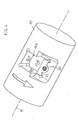
- the present invention will be explained with reference to a drill rod 10 which is rotatable about the axis of rotation 11, but can be used in a corresponding manner for each rotatable tool base holder about an axis.
- the drill rod 10 as illustrated basic tool holder has a recess with lateral contact surfaces 12a, b and c and a footprint 12d.
- a cassette 13 is inserted, which is fixable on its front surface by means of a wing wedge 33.
- the cartridge 13 carries in a recess a cutting insert 14, which in the present case at one corner carries a polycrystalline diamond insert 15. This cutting insert is secured by means of a clamping screw 16 in the cassette.
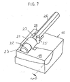
- an adjusting wedge 18 is arranged in a longitudinally extending recess 17, which is displaceable within the recess 17 by a distance measure a.
- the respective curved lateral surfaces 19 of the cassette 13 and the bore lateral surface 20 of the adjusting wedge 18 slide on one another, whereby their radial position can be adjusted by changing the position of the adjusting wedge 18 relative to the cassette 13 is.
- Fig. 6 and Fig. 7 show the respective adjustable end positions of the cassette, wherein in Fig. 5 and 6, the largest possible radial outward displacement of the cassette and in Fig. 7 of the minimum adjustable radial distance are shown.
- a eccentric pin 21 For axial displacement of the adjusting wedge is an eccentric pin 21 which is mounted in a radial bore of the cassette.
- This eccentric pin has an eccentrically arranged cylindrical extension 22 which engages in a slot 23 in the adjusting wedge 18.
- the cylindrical extension 22 changes its axial position, the adjusting wedge 18 is displaced axially in the cassette according to the change in position.
- the adjusting wedge 18 rests firmly with its flat surface 24 on the contact surface 12d, whereas the cassette 13 can be moved radially outwards by a stroke determined by the axial dimension a and the wedge angle ⁇ .
- Figs. 5 and 6 respectively show diagrams in which the maximum cassette stroke is achieved by the axial displacement a. If the dimension is a 0 (see Fig. 7), the minimum stroke of the cartridge 13 is set.
- a clamping sleeve 25 which is taken after the assembly of the cassette, the adjusting wedge and the eccentric pin.
- this has a hexagonal recess into which an Allen wrench 26 can be inserted.
- the eccentric body 21 is inserted into the existing bore 27 up to the stop provided by the annular surface 28.
- the adjusting wedge is inserted into the existing adapted recess of the cassette until the slot 23 of the adjusting wedge in the amount of the cylindrical extension 22, after which the eccentric pin and the cylinder part are lowered down into the position shown in Fig. 5-7.
- the clamping sleeve 25 is hammered, which locks the cassette, the clamping part and the eccentric with extension captive.
- the cassette can now be lowered into the projecting recess of the drill rod and fixed by means of the wing wedge 33, wherein the wing wedge surface 29 is actuated by actuation of the double threaded screw 30 for clamping the cassette over the front surface 31.
- the wing wedge 33 With only slight clamping pressure on the wing wedge 33, the radial adjustment of the cassette and thus of the cutting insert 14 and its cutting part 15 is made.
- the adjusting wedge 18 lies on the contact surface 12d.
- the cartridge performs a radial stroke, which enables a radial fine adjustment in the sense of alignment of the cutting edge of the cutting insert in the radial direction via the mutually sliding lateral surfaces 19 and 20.
- the wing wedge 33 is lowered by actuation of the double-threaded screw and thus causes the clamping of the cassette 13.
Landscapes
- Engineering & Computer Science (AREA)
- Mechanical Engineering (AREA)
- Cutting Tools, Boring Holders, And Turrets (AREA)
- Turning (AREA)
- Milling Processes (AREA)
- Auxiliary Devices For Machine Tools (AREA)
- Drilling Tools (AREA)
Description
- Die Erfindung betrifft ein Schneidwerkzeug für die spanabhebende Bearbeitung, mit einem um eine Achse drehbaren Werkzeuggrundhalter, der mindestens eine Ausnehmung für eine Kassette aufweist, die als Werkzeugträger für einen Schneideinsatz dient, und mit einer einen Exzenterzapfen und einen Stellkeil aufweisenden Verstelleinrichtung zur radialen Verschiebung der Kassette.
- Ein solches Schneidwerkzeug wird in der US 3,236,125 beschrieben.
- In der EP 0 739 258 B1 wird ein Fräser-Schneidwerkzeug mit einem Fräserkopf beschrieben, an dessen Stirnfläche mehrere Schneideinsätze angeordnet sind, die ihrerseits jeweils in einer Kassette befestigt sind. Jede der Kassetten ist in einer Nut in dem Fräserkopf angeordnet. Die Kassette besitzt eine Radialbohrung, in der ein Exzenterkörper anliegt, durch dessen Drehung die axiale Höhe der Kassette einstellbar ist. Nach Einstellung der axialen Höhe wird die Kassette durch Befestigungsschrauben am Werkzeugkopf fixiert.
- Bei dem Fräserkopf nach der EP 0 697 933 B1 sind in jeweiligen vertieften Nuten der Umfangsfläche eine einen Schneideinsatz tragende Kassette und eine Abstandshalterplatte angeordnet. Die aneinanderliegenden Oberflächen der Kassette und der Abstandshalterplatte sind mit Zahnungen ausgebildet. Ferner ist in radialer Richtung ein Zapfen in einer Öffnung in der Bodenfläche der Nut eingesetzt, dessen Kopf exzentrisch in bezug auf den glatten zylindrischen Teil des Zapfens ist. Der exzentrische Kopf ist in einer Vertiefung oder einer Durchgangsnut auf der Rückseite der Kassette plaziert und mit einem Inbus versehen, um den Zapfen drehen zu können. Durch Drehung des Exzenters kann die Kassette axial eingestellt werden. Zur radialen Einstellung des Schneideinsatzes bzw. der Kassette wird eine in ein Gewindelochder Kassette eingeschraubte Schraube verwendet.
- Es ist Aufgabe der vorliegenden Erfindung, bei einem Schneidwerkzeug der eingangs genannten Art eine zum Stand der Technik alternative Verstelleinrichtung zu schaffen, die leicht handhabbar ist, konstruktiv einfach aufgebaut ist und dennoch mit möglichst großer Präzision eine hinreichend exakte Radialverstellung der Kassette bzw. des hierauf befestigten Schneideinsatzes ermöglicht. Vorzugsweise soll diese Verstelleinrichtung auch für kleine Einbauräume nutzbar sein.
- Diese Aufgabe wird durch das Schneidwerkzeug nach Anspruch 1 gelöst.
- Erfindungsgemäß ist in einer Kassettenausnehmung ein Stellkeil angeordnet und in axialer Richtung mittels eines Exzenterzapfens verschiebbar. Durch die längsaxiale Bewegung des Stellkeiles innerhalb der Kassette wird die Kassette entsprechend dem durch den vorhandenen Keilwinkel bestimmten Hub gehoben oder gesenkt, womit sich der Radialabstand des Schneideinsatzes exakt festlegen läßt, etwa wenn ein Toleranzausgleich der dimensionsunterschiedlichen Schneideinsätze notwendig ist. Durch den Exzenter ist eine Radialverstellung der Kassette in beiden Richtungen, d.h. radial auswärts und radial einwärts ohne weitere Hilfsmittel möglich.
- Vorzugsweise ist der Exzenterzapfen in einer Radialbohrung der Kassette geführt, so daß über eine Einsteckbohrung ein Inbusschlüssel oder ein ähnliches Werkzeug in eine Ausnehmung des Exzenterzapfens radial von außen gesteckt und der Exzenterzapfen betätigt werden kann. Hierzu weist der Exzenterzapfen eine exzentrisch angeordnete zylinderförmige Verlängerung auf, die in eine passende Ausnehmung des Stellkeiles eingreift, so daß bei einer Drehung des Exzenters der Stellkeil verschoben und damit die Schneidkante des Schneideinsatzes in radialer Richtung exakt eingestellt werden kann.
- Nach einer weiteren Ausgestaltung ist die Kassette im Werkzeuggrundhalter mittels eines Flügelkeiles fixierbar, der über eine Schraube, vorzugsweise eine Doppelgewindeschraube in dem Werkzeuggrundhalter befestigbar ist, wobei der Flügelkeil im Spannzustand auf eine Kassettenfläche klemmend einwirkt. Dieser Flügelkeil dient dazu, die eingestellte Radial-Ausrichtung der Kassette und damit des Schneideinsatzes im Betrieb, d.h. bei der Durchführung der Zerspanungsoperationen, zu fixieren.
- Um den Exzenterzapfen verliersicher in der Kassette zu haltern, ist eine Spannhülse gegen eine Verschiebung des Exzenterzapfens in radialer Richtung vorgesehen.
- Der Keilwinkel des Stellkeiles liegt zwischen 8° und 12°, vorzugsweise bei 10°.
- Weitere Ausgestaltungen des erfindungsgemäßen Schneidwerkzeuges sowie dessen Vorteile werden im folgenden anhand der Zeichnungen erörtert. Es zeigen
- Fig. 1
- eine geschnittene Teilansicht einer Bohrstange mit einer montierten Kassette in einer Explosionsdarstellung,
- Fig. 2
- eine perspektivische Ansicht der Kassette mit dem Stellkeil in einer Explosionsdarstellung,
- Fig. 3
- eine perspektivische Ansicht der Bohrstange mit Flügelkeil in einer Explosionsdarstellung,
- Fig. 4
- eine Darstellung der Bohrstange mit montiertem Flügelkeil (ohne Kassette) und
- Fig. 5, 6 und 7
- jeweils verschiedene perspektivische Ansichten eines Kassetten-Schnittes.
- Die vorliegende Erfindung wird anhand einer Bohrstange 10, die um die Drehachse 11 rotierbar ist, erläutert, läßt sich jedoch in entsprechender Weise bei jedem um eine Achse drehbaren Werkzeuggrundhalters verwenden. Die Bohrstange 10 als dargestellter Werkzeuggrundhalter besitzt eine Ausnehmung mit seitlichen Anlageflächen 12a, b und c sowie einer Aufstandsfläche 12d. In diese Ausnehmung ist eine Kassette 13 einsteckbar, die an ihrer Vorderfläche mittels eines Flügelkeiles 33 fixierbar ist. Die Kassette 13 trägt in einer Ausnehmung einen Schneideinsatz 14, der im vorliegenden Fall an einer Ecke einen Einsatz 15 aus einem polykristallinen Diamant trägt. Dieser Schneideinsatz wird mittels einer Spannschraube 16 in der Kassette befestigt.
- Wie im einzelnen aus den Fig. 1, 2 sowie 5 bis 7 ersichtlich ist, ist in einer längsaxial verlaufenden Ausnehmung 17 ein Stellkeil 18 angeordnet, der innerhalb der Ausnehmung 17 um ein Wegmaß a verschiebbar ist. Bei dieser längsaxialen Verschiebung gleiten die jeweiligen gekrümmten Mantelflächen 19 der Kassette 13 sowie der Bohrungsmantelfläche 20 des Stellkeiles 18 aufeinander, wobei mit einer Veränderung der Lage des Stellkeiles 18 zur Kassette 13 deren radiale Lage einstellbar ist. Fig. 6 und Fig. 7 zeigen die jeweils einstellbaren Endlagen der Kassette, wobei in Fig. 5 und 6 die größtmögliche Radial-Auswärtsverschiebung der Kassette und in Fig. 7 der im Minimum einstellbare Radialabstand dargestellt sind. Zur Axialverschiebung des Stellkeiles dient ein Exzenterzapfen 21, der in einer Radialbohrung der Kassette gelagert ist. Dieser Exzenterzapfen besitzt eine exzentrisch angeordnete zylinderförmige Verlängerung 22, die in ein Langloch 23 im Stellkeil 18 eingreift. Durch Drehung des Exzenterzapfens 21 verändert die zylinderförmige Verlängerung 22 ihre axiale Lage, wobei der Stellkeil 18 entsprechend der Lageänderung axial in der Kassette verschoben wird. Der Stellkeil 18 liegt mit seiner ebenen Fläche 24 auf der Aufstandsfläche 12d fest auf, wohingegen die Kassette 13 um einen Hub radial auswärts bewegt werden kann, der durch das Axialmaß a sowie den Keilwinkel α bestimmt ist. Fig. 5 und 6 zeigen jeweils Darstellungen, bei denen der maximale Kassettenhub durch die Axialverschiebung a erreicht ist. Beträgt das Maß a 0 (siehe Fig. 7), ist der minimale Hub der Kassette 13 eingestellt.
- Zur Verliersicherung in radialer Richtung dient eine Spannhülse 25, die nach dem Zusammenbau der Kassette, des Stellkeiles und des Exzenterzapfens eingeschlagen wird.
- Zur Betätigung des Exzenters 21 besitzt dieser eine Sechskantausnehmung, in die ein Inbusschlüssel 26 einsteckbar ist.
- Zum Zusammenbau der in Fig. 1 dargestellten Kassette wird zunächst der Exzenterkörper 21 in die vorhandene Bohrung 27 bis zum durch die Ringfläche 28 vorgesehenen Anschlag eingeschoben. Anschließend wird der Stellkeil in die vorhandene angepaßte Ausnehmung der Kassette eingeführt, bis das Langloch 23 des Stellkeiles in Höhe der zylindrischen Verlängerung 22 liegt, wonach der Exzenterzapfen und das Zylinderteil nach unten in die in Fig. 5 bis 7 dargestellte Lage abgesenkt werden. Nach diesem Einfädeln wird die Spannhülse 25 eingeschlagen, welche die Kassette, den Spannteil sowie den Exzenter mit Verlängerung verliersicher arretiert. Die Kassette kann nun in die vorsehende Ausnehmung der Bohrstange abgesenkt und mittels des Flügelkeiles 33 befestigt werden, wobei die Flügelkeilfläche 29 durch Betätigung der Doppelgewindeschraube 30 zur Klemmung der Kassette über deren Vorderfläche 31 betätigt wird. Bei nur leichtem Klemmdruck über den Flügelkeil 33 wird die Radialeinstellung der Kassette und damit des Schneideinsatzes 14 bzw. dessen Schneidteil 15 vorgenommen. Bei vormontierter Kassette liegt der Stellkeil 18 auf der Aufstandsfläche 12d auf. Führt man über eine vorhandene Bohrung 32 einen Sechskantschraubendreher 26 ein und bringt man diesen mit einer entsprechenden Ausnehmung des Exzenterzapfens 21 in Eingriff, so kann durch Drehung des Exzenterzapfens und damit verbundener axialer Verschiebung des Zylinderzapfens 22 der Stellkeil 18 in axialer Richtung zwischen den Axialstellungen a = 0 (Fig. 7) und dem in Fig. 5 und 6 dargestellten Maß von a = 2 bis 3 mm verschoben werden. Über die aneinandergleitenden Mantelflächen 19 und 20 vollzieht die Kassette einen Radialhub, der eine radiale Feineinstellung im Sinne einer Ausrichtung der Schneidkante des Schneideinsatzes in radialer Richtung ermöglicht. Nach der optimalen radialen Einstellung der Kassette wird durch Betätigung der Doppelgewindeschraube 30 der Flügelkeil 33 abgesenkt und damit die Klemmung der Kassette 13 bewirkt.
- Besonders vorteilhaft bei der erfindungsgemäßen Anordnung ist es, daß in leicht handhabbarer Weise die Radialverstellung der Kassette durch radiales Einführen des Sechskantschlüssels oder eines anderen Schraubendrehers 26 durchführbar ist.
Claims (5)
- Schneidwerkzeug für die spanabhebende Bearbeitung, mit einem um eine Achse (11) drehbaren Werkzeuggrundhalter (10), der mindestens eine Ausnehmung für eine Kassette (13) aufweist, die als Werkzeugträger für einen Schneideinsatz (14) dient und mit einer einen Exzenterzapfen (21) und einen Stellkeil (18) aufweisenden Verstelleinrichtung zur radialen Verschiebung der Kassette (13),
dadurch gekennzeichnet,
dass der Stellkeil in einer Kassettenausnehmung (17) angeordnet ist, die den Stellkeil derart umgreift, dass dieser lediglich in axialer Richtung mittels des Exzenterzapfens (21) verschiebbar ist. - Schneidwerkzeug nach Anspruch 1, dadurch gekennzeichnet, daß der Exzenterzapfen (21) in einer Radialbohrung (27) der Kassette (13) geführt ist und eine exzentrisch angeordnete zylinderförmige Verlängerung (22) aufweist, die in ein Langloch (23) des Stellkeiles (18) eingreift.
- Schneidwerkzeug nach Anspruch 1 oder 2, dadurch gekennzeichnet, daß die Kassette (13) im Werkzeuggrundhalter (10) mittels eines Flügelkeiles (33) fixierbar ist, der über eine Schraube, vorzugsweise eine Doppelgewindeschraube (30) in dem Werkzeuggrundhalter (10) befestigbar ist, wobei der Flügelkeil (33) im Spannzustand auf eine Kassettenfläche (31) klemmend einwirkt.
- Schneidwerkzeug nach einem der Ansprüche 1 bis 3, dadurch gekennzeichnet, daß der Exzenterzapfen (21) mittels einer Spannhülse (25) gegen eine Verschiebung in radialer Richtung gesichert ist.
- Schneidwerkzeug nach einem der Ansprüche 1 bis 4, dadurch gekennzeichnet, daß der Keilwinkel (α) des Stellkeiles (18) 10° ± 2° beträgt.
Applications Claiming Priority (3)
| Application Number | Priority Date | Filing Date | Title |
|---|---|---|---|
| DE10234030 | 2002-07-26 | ||
| DE10234030A DE10234030A1 (de) | 2002-07-26 | 2002-07-26 | Schneidwerkzeug für die spanabhebende Bearbeitung |
| PCT/DE2003/002197 WO2004016379A1 (de) | 2002-07-26 | 2003-07-02 | Schneidwerkzeug für die spanabhebende bearbeitung |
Publications (2)
| Publication Number | Publication Date |
|---|---|
| EP1536904A1 EP1536904A1 (de) | 2005-06-08 |
| EP1536904B1 true EP1536904B1 (de) | 2006-10-04 |
Family
ID=30010391
Family Applications (1)
| Application Number | Title | Priority Date | Filing Date |
|---|---|---|---|
| EP03787621A Expired - Lifetime EP1536904B1 (de) | 2002-07-26 | 2003-07-02 | Schneidwerkzeug für die spanabhebende bearbeitung |
Country Status (8)
| Country | Link |
|---|---|
| US (1) | US7287938B2 (de) |
| EP (1) | EP1536904B1 (de) |
| CN (1) | CN1665630A (de) |
| AT (1) | ATE341413T1 (de) |
| AU (1) | AU2003250286A1 (de) |
| DE (2) | DE10234030A1 (de) |
| PL (1) | PL372959A1 (de) |
| WO (1) | WO2004016379A1 (de) |
Families Citing this family (14)
| Publication number | Priority date | Publication date | Assignee | Title |
|---|---|---|---|---|
| DE202004002491U1 (de) * | 2004-02-17 | 2005-08-18 | Kennametal Inc. | Schneidplatte, insbesondere für ein Ausdrehwerkzeug |
| US20090290944A1 (en) * | 2008-05-22 | 2009-11-26 | Gamble Kevin M | Cartridge assembly for cutting tool |
| EP2773478B1 (de) * | 2011-11-04 | 2016-01-06 | Walter AG | Kartusche mit grob- und feineinstellungsmitteln |
| US20140003872A1 (en) * | 2012-05-16 | 2014-01-02 | Kennametal Inc. | Cassette for a milling cutter |
| DE102013206093B4 (de) * | 2013-04-05 | 2021-11-18 | Kennametal Inc. | Werkzeugkassette zum Einsetzen in einem Kassettensitz sowie Werkzeug mit einem Kassettensitz für eine derartige Werkzeugkassette |
| US10010953B2 (en) | 2014-03-19 | 2018-07-03 | Kennametal Inc. | Wedge clamp and insert cartridge for cutting tool |
| EP3069809B1 (de) | 2014-05-15 | 2021-10-20 | Tungaloy Corporation | Einsatzbefestigungsmechanismus und schneidwerkzeug |
| US10384279B2 (en) * | 2015-07-10 | 2019-08-20 | Tungaloy Corporation | Tool, adjustment mechanism, tool body and cutting tool |
| DE102016217239A1 (de) * | 2016-09-09 | 2018-03-15 | Gühring KG | Schneidenträger und zerspanungswerkzeug mit einem schneidenträger |
| DE102016217243A1 (de) * | 2016-09-09 | 2018-03-15 | Gühring KG | Mehrschneidiges zerspanungswerkzeug und verfahren zum bearbeiten einer lagergasse |
| US10131005B2 (en) * | 2017-01-10 | 2018-11-20 | Kennametal Inc. | Adjustable cartridge assembly for cutting tool |
| CN110000428B (zh) * | 2019-03-29 | 2024-01-05 | 太仓瑞鼎精密机械科技有限公司 | 机夹刀片式可调铰刀 |
| CN111085648A (zh) * | 2020-01-17 | 2020-05-01 | 东莞市泰基山机械设备有限公司 | 一种新型冷镦机 |
| DE102022213281A1 (de) * | 2022-12-08 | 2024-06-13 | Kennametal Inc. | Rotationswerkzeug, insbesondere Fräser |
Family Cites Families (33)
| Publication number | Priority date | Publication date | Assignee | Title |
|---|---|---|---|---|
| NL125964C (de) * | 1963-07-26 | |||
| US3232144A (en) * | 1963-10-28 | 1966-02-01 | De Vlieg Machine Co | Adjustable tool holder |
| US3189976A (en) * | 1963-12-27 | 1965-06-22 | Gen Electric | Adjustable cutting toolholder |
| GB1063441A (en) * | 1964-03-02 | 1967-03-30 | Wickman Wimet Ltd | Cutting tools |
| DE2112689A1 (de) * | 1971-03-16 | 1972-09-28 | Murex Ltd | Einstellvorrichtung zur Radialverstellung eines an einer Bohrstange befestigten Bohrwerkzeughalters |
| US3755868A (en) * | 1971-07-23 | 1973-09-04 | Gen Electric | Adjustable cutting tool |
| US3802043A (en) * | 1972-10-30 | 1974-04-09 | C Garih | Milling cutter with mechanically clamped teeth |
| DE2556977A1 (de) * | 1975-12-18 | 1977-06-30 | Botek Praezisions Bohrtechnik | Tiefbohrwerkzeug zum aufbohren |
| US4030176A (en) * | 1976-03-29 | 1977-06-21 | General Electric Company | Adjustable cutting tool |
| US4018542A (en) * | 1976-06-03 | 1977-04-19 | Lindsay Harold W | Adjustable tool holder for boring bar |
| US4318647A (en) * | 1980-04-07 | 1982-03-09 | General Electric Company | Adjustable insert seat and wedge assembly for an indexable boring cutter |
| DE3026513C2 (de) * | 1980-07-12 | 1982-08-26 | Komet Stahlhalter- Und Werkzeugfabrik Robert Breuning Gmbh, 7122 Besigheim | Werkzeug zum Aufbohren und Plansenken |
| DE3317916A1 (de) * | 1983-05-17 | 1984-11-22 | Walter Kieninger KG Hartmetallwerkzeugfabrik, 7630 Lahr | Fraeswerkzeug |
| SE454490B (sv) * | 1984-07-05 | 1988-05-09 | Seco Tools Ab | Fres med instellbar kassett |
| DE3611672A1 (de) * | 1986-04-07 | 1987-10-08 | Guehring Gottlieb Fa | Zerspanungswerkzeug |
| DE3708034A1 (de) * | 1987-03-12 | 1988-09-22 | Zerspanungstech Gmbh & Co Kg | Messerkopf |
| DE3801394A1 (de) * | 1988-01-19 | 1989-07-27 | Zerspannungstech Gmbh & Co Kg | Messerkopf |
| CH679467A5 (de) * | 1989-06-29 | 1992-02-28 | Maag Zahnraeder & Maschinen Ag | |
| US5042733A (en) * | 1990-08-06 | 1991-08-27 | Hans Hench | Rotary cutter, particularly for granulating plastic material |
| US5163788A (en) * | 1991-01-10 | 1992-11-17 | Gte Valenite Corporation | Rotary slotting tool having staggered cutting elements |
| SE501915C2 (sv) * | 1993-03-18 | 1995-06-19 | Sandvik Ab | Finfräs med urtag för axiellt inställbara kassetter |
| SE502085C2 (sv) | 1993-04-27 | 1995-08-07 | Sandvik Ab | Fräshuvud med rilltandade kassetter |
| US5454667A (en) * | 1993-09-30 | 1995-10-03 | Master Tool Corporation | Adjustable cartridge for cutting head of a machine tool |
| JP3628695B2 (ja) | 1994-01-14 | 2005-03-16 | サンドビック アクティエボラーグ | スローアウェイチップおよび切削工具 |
| ATE240179T1 (de) * | 1996-03-19 | 2003-05-15 | Iscar Ltd | Schneidwerkzeuganordnung |
| US5735649A (en) * | 1996-10-08 | 1998-04-07 | Kaiser Precision Tooling, Inc. | Machine tool cutter position adjustment device |
| SE512751C2 (sv) * | 1997-04-11 | 2000-05-08 | Sandvik Ab | Skärande verktyg |
| US5975811A (en) * | 1997-07-31 | 1999-11-02 | Briese Industrial Technologies, Inc. | Cutting insert cartridge arrangement |
| DE19800440A1 (de) * | 1998-01-08 | 1999-07-15 | Maier Kg Andreas | Messerkopf mit ein- bis dreidimensional verstellbarem Schneideinsatz und mit formschlüssig aufgenommenem Schneideinsatz |
| DE10005467A1 (de) * | 2000-02-08 | 2001-08-16 | Stehle Gmbh & Co Kg | Messerkopf |
| US7114890B2 (en) * | 2001-02-13 | 2006-10-03 | Valenite Inc. | Cutting tool adjustment device |
| US6702526B2 (en) * | 2002-04-29 | 2004-03-09 | Kennametal Inc. | Cutting tool |
| US7014393B2 (en) * | 2003-02-07 | 2006-03-21 | Dr. Joerg Guehring | Clamping and adjustment apparatus for a cutting tool |
-
2002
- 2002-07-26 DE DE10234030A patent/DE10234030A1/de not_active Withdrawn
-
2003
- 2003-07-02 PL PL03372959A patent/PL372959A1/xx unknown
- 2003-07-02 CN CN03816110.9A patent/CN1665630A/zh active Pending
- 2003-07-02 AT AT03787621T patent/ATE341413T1/de not_active IP Right Cessation
- 2003-07-02 EP EP03787621A patent/EP1536904B1/de not_active Expired - Lifetime
- 2003-07-02 AU AU2003250286A patent/AU2003250286A1/en not_active Abandoned
- 2003-07-02 US US10/523,136 patent/US7287938B2/en not_active Expired - Fee Related
- 2003-07-02 DE DE50305289T patent/DE50305289D1/de not_active Expired - Lifetime
- 2003-07-02 WO PCT/DE2003/002197 patent/WO2004016379A1/de not_active Ceased
Also Published As
| Publication number | Publication date |
|---|---|
| US20050260045A1 (en) | 2005-11-24 |
| EP1536904A1 (de) | 2005-06-08 |
| AU2003250286A1 (en) | 2004-03-03 |
| DE50305289D1 (de) | 2006-11-16 |
| ATE341413T1 (de) | 2006-10-15 |
| US7287938B2 (en) | 2007-10-30 |
| PL372959A1 (en) | 2005-08-08 |
| CN1665630A (zh) | 2005-09-07 |
| WO2004016379A1 (de) | 2004-02-26 |
| DE10234030A1 (de) | 2004-02-05 |
Similar Documents
| Publication | Publication Date | Title |
|---|---|---|
| DE102008022844B4 (de) | Werkzeug zum Dreh-Dreh-Räumen oder Außenfräsen von Werkstücken | |
| EP0884124B1 (de) | Fräswerkzeug mit axialer Einstellung | |
| DE69410252T2 (de) | Fräser mit ausnehmungen für einstellbare einsatzhalter | |
| EP1293280B3 (de) | Spanabhebendes Werkzeug mit Wendeschneidplatte | |
| DE2235782C2 (de) | Bohrkopf | |
| EP1536904B1 (de) | Schneidwerkzeug für die spanabhebende bearbeitung | |
| EP1140400B1 (de) | Zerspanungs-werkzeug für die hochgeschwindigkeitsbearbeitung | |
| DE202008006375U1 (de) | Werkzeug zum Dreh-Dreh-Räumen oder Außenfräsen von Werkstücken | |
| EP1864741B1 (de) | Werkzeug für die Bearbeitung eines Werkstücks | |
| EP2300184B1 (de) | Werkzeug mit befestigungseinrichtung | |
| DE10340493B4 (de) | Fräswerkzeug mit einstellbarem Plattensitz | |
| DE3140905C2 (de) | Planfräsmesserkopf | |
| DE102011082964A1 (de) | Werkzeugkassette und Zerspanungswerkzeug mit einer Werkzeugkassette | |
| EP0693013B1 (de) | Modulares werkzeugsystem | |
| DE10108103B9 (de) | Maschinenwerkzeug mit verstellbarer Schneidplatte | |
| DE10250018A1 (de) | Maschinenwerkzeug mit verstellbarer Schneide | |
| DE202015101365U1 (de) | Spannfutter | |
| DE10238451A1 (de) | Scheibenförmiges oder leistenförmiges Werkzeug | |
| EP2799173B1 (de) | Messerkopf und schneidplatte | |
| DE19708601A1 (de) | Reib- und Senk-Schneidwerkzeug | |
| EP0850715A1 (de) | Wendeschneidwerkzeug | |
| DE3701053A1 (de) | Messerkopf | |
| DE20305081U1 (de) | Spann- und Justiervorrichtung für ein Zerspanungswerkzeug | |
| DE102006052051A1 (de) | Werkzeughalter | |
| EP0941822B1 (de) | Hartmetall-Schneidplatte für die Holzbearbeitung |
Legal Events
| Date | Code | Title | Description |
|---|---|---|---|
| PUAI | Public reference made under article 153(3) epc to a published international application that has entered the european phase |
Free format text: ORIGINAL CODE: 0009012 |
|
| 17P | Request for examination filed |
Effective date: 20050119 |
|
| AK | Designated contracting states |
Kind code of ref document: A1 Designated state(s): AT BE BG CH CY CZ DE DK EE ES FI FR GB GR HU IE IT LI LU MC NL PT RO SE SI SK TR |
|
| AX | Request for extension of the european patent |
Extension state: AL LT LV MK |
|
| DAX | Request for extension of the european patent (deleted) | ||
| GRAJ | Information related to disapproval of communication of intention to grant by the applicant or resumption of examination proceedings by the epo deleted |
Free format text: ORIGINAL CODE: EPIDOSDIGR1 |
|
| GRAP | Despatch of communication of intention to grant a patent |
Free format text: ORIGINAL CODE: EPIDOSNIGR1 |
|
| GRAP | Despatch of communication of intention to grant a patent |
Free format text: ORIGINAL CODE: EPIDOSNIGR1 |
|
| RAP1 | Party data changed (applicant data changed or rights of an application transferred) |
Owner name: KENNAMETAL WIDIA PRODUKTIONS GMBH & CO. KG |
|
| GRAS | Grant fee paid |
Free format text: ORIGINAL CODE: EPIDOSNIGR3 |
|
| GRAA | (expected) grant |
Free format text: ORIGINAL CODE: 0009210 |
|
| AK | Designated contracting states |
Kind code of ref document: B1 Designated state(s): AT BE BG CH CY CZ DE DK EE ES FI FR GB GR HU IE IT LI LU MC NL PT RO SE SI SK TR |
|
| PG25 | Lapsed in a contracting state [announced via postgrant information from national office to epo] |
Ref country code: CZ Free format text: LAPSE BECAUSE OF FAILURE TO SUBMIT A TRANSLATION OF THE DESCRIPTION OR TO PAY THE FEE WITHIN THE PRESCRIBED TIME-LIMIT Effective date: 20061004 Ref country code: IT Free format text: LAPSE BECAUSE OF FAILURE TO SUBMIT A TRANSLATION OF THE DESCRIPTION OR TO PAY THE FEE WITHIN THE PRESCRIBED TIME-LIMIT;WARNING: LAPSES OF ITALIAN PATENTS WITH EFFECTIVE DATE BEFORE 2007 MAY HAVE OCCURRED AT ANY TIME BEFORE 2007. THE CORRECT EFFECTIVE DATE MAY BE DIFFERENT FROM THE ONE RECORDED. Effective date: 20061004 Ref country code: IE Free format text: LAPSE BECAUSE OF FAILURE TO SUBMIT A TRANSLATION OF THE DESCRIPTION OR TO PAY THE FEE WITHIN THE PRESCRIBED TIME-LIMIT Effective date: 20061004 Ref country code: RO Free format text: LAPSE BECAUSE OF FAILURE TO SUBMIT A TRANSLATION OF THE DESCRIPTION OR TO PAY THE FEE WITHIN THE PRESCRIBED TIME-LIMIT Effective date: 20061004 Ref country code: NL Free format text: LAPSE BECAUSE OF FAILURE TO SUBMIT A TRANSLATION OF THE DESCRIPTION OR TO PAY THE FEE WITHIN THE PRESCRIBED TIME-LIMIT Effective date: 20061004 Ref country code: SI Free format text: LAPSE BECAUSE OF FAILURE TO SUBMIT A TRANSLATION OF THE DESCRIPTION OR TO PAY THE FEE WITHIN THE PRESCRIBED TIME-LIMIT Effective date: 20061004 Ref country code: FI Free format text: LAPSE BECAUSE OF FAILURE TO SUBMIT A TRANSLATION OF THE DESCRIPTION OR TO PAY THE FEE WITHIN THE PRESCRIBED TIME-LIMIT Effective date: 20061004 Ref country code: SK Free format text: LAPSE BECAUSE OF FAILURE TO SUBMIT A TRANSLATION OF THE DESCRIPTION OR TO PAY THE FEE WITHIN THE PRESCRIBED TIME-LIMIT Effective date: 20061004 |
|
| REG | Reference to a national code |
Ref country code: GB Ref legal event code: FG4D Free format text: NOT ENGLISH |
|
| GBT | Gb: translation of ep patent filed (gb section 77(6)(a)/1977) |
Effective date: 20061004 |
|
| REG | Reference to a national code |
Ref country code: CH Ref legal event code: EP |
|
| REG | Reference to a national code |
Ref country code: IE Ref legal event code: FG4D Free format text: LANGUAGE OF EP DOCUMENT: GERMAN |
|
| REF | Corresponds to: |
Ref document number: 50305289 Country of ref document: DE Date of ref document: 20061116 Kind code of ref document: P |
|
| PG25 | Lapsed in a contracting state [announced via postgrant information from national office to epo] |
Ref country code: BG Free format text: LAPSE BECAUSE OF FAILURE TO SUBMIT A TRANSLATION OF THE DESCRIPTION OR TO PAY THE FEE WITHIN THE PRESCRIBED TIME-LIMIT Effective date: 20070104 Ref country code: DK Free format text: LAPSE BECAUSE OF FAILURE TO SUBMIT A TRANSLATION OF THE DESCRIPTION OR TO PAY THE FEE WITHIN THE PRESCRIBED TIME-LIMIT Effective date: 20070104 |
|
| REG | Reference to a national code |
Ref country code: SE Ref legal event code: TRGR |
|
| PG25 | Lapsed in a contracting state [announced via postgrant information from national office to epo] |
Ref country code: ES Free format text: LAPSE BECAUSE OF FAILURE TO SUBMIT A TRANSLATION OF THE DESCRIPTION OR TO PAY THE FEE WITHIN THE PRESCRIBED TIME-LIMIT Effective date: 20070115 |
|
| PG25 | Lapsed in a contracting state [announced via postgrant information from national office to epo] |
Ref country code: PT Free format text: LAPSE BECAUSE OF FAILURE TO SUBMIT A TRANSLATION OF THE DESCRIPTION OR TO PAY THE FEE WITHIN THE PRESCRIBED TIME-LIMIT Effective date: 20070316 |
|
| NLV1 | Nl: lapsed or annulled due to failure to fulfill the requirements of art. 29p and 29m of the patents act | ||
| ET | Fr: translation filed | ||
| REG | Reference to a national code |
Ref country code: IE Ref legal event code: FD4D |
|
| PLBE | No opposition filed within time limit |
Free format text: ORIGINAL CODE: 0009261 |
|
| STAA | Information on the status of an ep patent application or granted ep patent |
Free format text: STATUS: NO OPPOSITION FILED WITHIN TIME LIMIT |
|
| 26N | No opposition filed |
Effective date: 20070705 |
|
| BERE | Be: lapsed |
Owner name: KENNAMETAL WIDIA PRODUKTIONS G.M.B.H. & CO. KG Effective date: 20070731 |
|
| REG | Reference to a national code |
Ref country code: CH Ref legal event code: PL |
|
| PG25 | Lapsed in a contracting state [announced via postgrant information from national office to epo] |
Ref country code: GR Free format text: LAPSE BECAUSE OF FAILURE TO SUBMIT A TRANSLATION OF THE DESCRIPTION OR TO PAY THE FEE WITHIN THE PRESCRIBED TIME-LIMIT Effective date: 20070105 Ref country code: LI Free format text: LAPSE BECAUSE OF NON-PAYMENT OF DUE FEES Effective date: 20070731 Ref country code: MC Free format text: LAPSE BECAUSE OF NON-PAYMENT OF DUE FEES Effective date: 20070731 Ref country code: CH Free format text: LAPSE BECAUSE OF NON-PAYMENT OF DUE FEES Effective date: 20070731 |
|
| PG25 | Lapsed in a contracting state [announced via postgrant information from national office to epo] |
Ref country code: EE Free format text: LAPSE BECAUSE OF FAILURE TO SUBMIT A TRANSLATION OF THE DESCRIPTION OR TO PAY THE FEE WITHIN THE PRESCRIBED TIME-LIMIT Effective date: 20061004 |
|
| PG25 | Lapsed in a contracting state [announced via postgrant information from national office to epo] |
Ref country code: BE Free format text: LAPSE BECAUSE OF NON-PAYMENT OF DUE FEES Effective date: 20070731 |
|
| PG25 | Lapsed in a contracting state [announced via postgrant information from national office to epo] |
Ref country code: LU Free format text: LAPSE BECAUSE OF NON-PAYMENT OF DUE FEES Effective date: 20070702 Ref country code: CY Free format text: LAPSE BECAUSE OF FAILURE TO SUBMIT A TRANSLATION OF THE DESCRIPTION OR TO PAY THE FEE WITHIN THE PRESCRIBED TIME-LIMIT Effective date: 20061004 |
|
| PG25 | Lapsed in a contracting state [announced via postgrant information from national office to epo] |
Ref country code: HU Free format text: LAPSE BECAUSE OF FAILURE TO SUBMIT A TRANSLATION OF THE DESCRIPTION OR TO PAY THE FEE WITHIN THE PRESCRIBED TIME-LIMIT Effective date: 20070405 Ref country code: TR Free format text: LAPSE BECAUSE OF FAILURE TO SUBMIT A TRANSLATION OF THE DESCRIPTION OR TO PAY THE FEE WITHIN THE PRESCRIBED TIME-LIMIT Effective date: 20061004 |
|
| PGFP | Annual fee paid to national office [announced via postgrant information from national office to epo] |
Ref country code: AT Payment date: 20100714 Year of fee payment: 8 Ref country code: SE Payment date: 20100715 Year of fee payment: 8 |
|
| PGFP | Annual fee paid to national office [announced via postgrant information from national office to epo] |
Ref country code: GB Payment date: 20110622 Year of fee payment: 9 |
|
| PGFP | Annual fee paid to national office [announced via postgrant information from national office to epo] |
Ref country code: FR Payment date: 20110727 Year of fee payment: 9 |
|
| PGFP | Annual fee paid to national office [announced via postgrant information from national office to epo] |
Ref country code: IT Payment date: 20110715 Year of fee payment: 9 |
|
| REG | Reference to a national code |
Ref country code: SE Ref legal event code: EUG |
|
| REG | Reference to a national code |
Ref country code: AT Ref legal event code: MM01 Ref document number: 341413 Country of ref document: AT Kind code of ref document: T Effective date: 20110702 |
|
| PGFP | Annual fee paid to national office [announced via postgrant information from national office to epo] |
Ref country code: DE Payment date: 20120627 Year of fee payment: 10 |
|
| PG25 | Lapsed in a contracting state [announced via postgrant information from national office to epo] |
Ref country code: AT Free format text: LAPSE BECAUSE OF NON-PAYMENT OF DUE FEES Effective date: 20110702 |
|
| GBPC | Gb: european patent ceased through non-payment of renewal fee |
Effective date: 20120702 |
|
| REG | Reference to a national code |
Ref country code: FR Ref legal event code: ST Effective date: 20130329 |
|
| PG25 | Lapsed in a contracting state [announced via postgrant information from national office to epo] |
Ref country code: FR Free format text: LAPSE BECAUSE OF NON-PAYMENT OF DUE FEES Effective date: 20120731 Ref country code: GB Free format text: LAPSE BECAUSE OF NON-PAYMENT OF DUE FEES Effective date: 20120702 Ref country code: SE Free format text: LAPSE BECAUSE OF NON-PAYMENT OF DUE FEES Effective date: 20110703 |
|
| PG25 | Lapsed in a contracting state [announced via postgrant information from national office to epo] |
Ref country code: IT Free format text: LAPSE BECAUSE OF NON-PAYMENT OF DUE FEES Effective date: 20120702 |
|
| PG25 | Lapsed in a contracting state [announced via postgrant information from national office to epo] |
Ref country code: DE Free format text: LAPSE BECAUSE OF NON-PAYMENT OF DUE FEES Effective date: 20140201 |
|
| REG | Reference to a national code |
Ref country code: DE Ref legal event code: R119 Ref document number: 50305289 Country of ref document: DE Effective date: 20140201 |