EP1536546A1 - Linearstellglied und pumpen- und kompressoreinrichtungen mit dem stellglied - Google Patents
Linearstellglied und pumpen- und kompressoreinrichtungen mit dem stellglied Download PDFInfo
- Publication number
- EP1536546A1 EP1536546A1 EP03760162A EP03760162A EP1536546A1 EP 1536546 A1 EP1536546 A1 EP 1536546A1 EP 03760162 A EP03760162 A EP 03760162A EP 03760162 A EP03760162 A EP 03760162A EP 1536546 A1 EP1536546 A1 EP 1536546A1
- Authority
- EP
- European Patent Office
- Prior art keywords
- yokes
- linear actuator
- coil
- magnets
- yoke
- Prior art date
- Legal status (The legal status is an assumption and is not a legal conclusion. Google has not performed a legal analysis and makes no representation as to the accuracy of the status listed.)
- Withdrawn
Links
- 238000004519 manufacturing process Methods 0.000 abstract description 8
- 230000005389 magnetism Effects 0.000 abstract description 2
- 238000010586 diagram Methods 0.000 description 19
- 238000004804 winding Methods 0.000 description 7
- 239000011347 resin Substances 0.000 description 6
- 229920005989 resin Polymers 0.000 description 6
- XEEYBQQBJWHFJM-UHFFFAOYSA-N Iron Chemical compound [Fe] XEEYBQQBJWHFJM-UHFFFAOYSA-N 0.000 description 3
- 239000000843 powder Substances 0.000 description 3
- 239000012530 fluid Substances 0.000 description 2
- 230000005415 magnetization Effects 0.000 description 2
- 230000004048 modification Effects 0.000 description 2
- 238000012986 modification Methods 0.000 description 2
- 238000000465 moulding Methods 0.000 description 2
- 230000000630 rising effect Effects 0.000 description 2
- 239000000654 additive Substances 0.000 description 1
- 239000011248 coating agent Substances 0.000 description 1
- 238000000576 coating method Methods 0.000 description 1
- 229910052742 iron Inorganic materials 0.000 description 1
- 238000003754 machining Methods 0.000 description 1
- 239000000463 material Substances 0.000 description 1
- 229910001172 neodymium magnet Inorganic materials 0.000 description 1
- 230000002093 peripheral effect Effects 0.000 description 1
- 238000005498 polishing Methods 0.000 description 1
- 229910052761 rare earth metal Inorganic materials 0.000 description 1
- 150000002910 rare earth metals Chemical class 0.000 description 1
- 238000005245 sintering Methods 0.000 description 1
- 239000007787 solid Substances 0.000 description 1
Images



Classifications
-
- H—ELECTRICITY
- H02—GENERATION; CONVERSION OR DISTRIBUTION OF ELECTRIC POWER
- H02K—DYNAMO-ELECTRIC MACHINES
- H02K1/00—Details of the magnetic circuit
- H02K1/06—Details of the magnetic circuit characterised by the shape, form or construction
- H02K1/22—Rotating parts of the magnetic circuit
- H02K1/27—Rotor cores with permanent magnets
-
- F—MECHANICAL ENGINEERING; LIGHTING; HEATING; WEAPONS; BLASTING
- F04—POSITIVE - DISPLACEMENT MACHINES FOR LIQUIDS; PUMPS FOR LIQUIDS OR ELASTIC FLUIDS
- F04B—POSITIVE-DISPLACEMENT MACHINES FOR LIQUIDS; PUMPS
- F04B17/00—Pumps characterised by combination with, or adaptation to, specific driving engines or motors
- F04B17/03—Pumps characterised by combination with, or adaptation to, specific driving engines or motors driven by electric motors
-
- F—MECHANICAL ENGINEERING; LIGHTING; HEATING; WEAPONS; BLASTING
- F04—POSITIVE - DISPLACEMENT MACHINES FOR LIQUIDS; PUMPS FOR LIQUIDS OR ELASTIC FLUIDS
- F04B—POSITIVE-DISPLACEMENT MACHINES FOR LIQUIDS; PUMPS
- F04B35/00—Piston pumps specially adapted for elastic fluids and characterised by the driving means to their working members, or by combination with, or adaptation to, specific driving engines or motors, not otherwise provided for
- F04B35/04—Piston pumps specially adapted for elastic fluids and characterised by the driving means to their working members, or by combination with, or adaptation to, specific driving engines or motors, not otherwise provided for the means being electric
- F04B35/045—Piston pumps specially adapted for elastic fluids and characterised by the driving means to their working members, or by combination with, or adaptation to, specific driving engines or motors, not otherwise provided for the means being electric using solenoids
-
- H—ELECTRICITY
- H02—GENERATION; CONVERSION OR DISTRIBUTION OF ELECTRIC POWER
- H02K—DYNAMO-ELECTRIC MACHINES
- H02K1/00—Details of the magnetic circuit
- H02K1/06—Details of the magnetic circuit characterised by the shape, form or construction
- H02K1/22—Rotating parts of the magnetic circuit
- H02K1/27—Rotor cores with permanent magnets
- H02K1/2706—Inner rotors
- H02K1/272—Inner rotors the magnetisation axis of the magnets being perpendicular to the rotor axis
- H02K1/274—Inner rotors the magnetisation axis of the magnets being perpendicular to the rotor axis the rotor consisting of two or more circumferentially positioned magnets
- H02K1/2753—Inner rotors the magnetisation axis of the magnets being perpendicular to the rotor axis the rotor consisting of two or more circumferentially positioned magnets the rotor consisting of magnets or groups of magnets arranged with alternating polarity
- H02K1/276—Magnets embedded in the magnetic core, e.g. interior permanent magnets [IPM]
-
- H—ELECTRICITY
- H02—GENERATION; CONVERSION OR DISTRIBUTION OF ELECTRIC POWER
- H02K—DYNAMO-ELECTRIC MACHINES
- H02K33/00—Motors with reciprocating, oscillating or vibrating magnet, armature or coil system
- H02K33/16—Motors with reciprocating, oscillating or vibrating magnet, armature or coil system with polarised armatures moving in alternate directions by reversal or energisation of a single coil system
Definitions
- the present invention relates to a linear actuator, and to a pump device and a compressor device in which this linear actuator is used. More specifically, the present invention relates to a linear actuator with a structure wherein inner yokes and outer yokes are disposed in the circumferential direction.
- a motor that outputs rotational movement is used as an actuator for a pump device or compressor device in which a piston moves rectilinearly within a cylinder. Therefore, problems are encountered in that power is not transmitted efficiently because the rotational movement must be converted to rectilinear movement by a crankshaft or the like between an output shaft of the motor and the piston.
- the linear actuator disclosed herein includes two or four inner yokes 103, 203, two or four outer yokes 104, 204 disposed so as to form gaps 109, 209 with outer surfaces of the inner yokes 103, 203, coils (not shown) wound around the outer yokes 104, 204, and magnets 106, 206 disposed in the gaps 109, 209.
- a layered structure is used for the inner yokes 103, 203 and the outer yokes 104, 204 so that multiple magnetic thin plates are layered on opposite sides so as to describe an arc, and arcuate components are used as magnets 106, 206 to match the shape thereof.
- FIG. 7(C) Another possibility is shown in FIG. 7(C), wherein a cylindrical inner yoke 303 and a cylindrical outer yoke 304 face each other via a prescribed gap 309, and a cylindrical magnet 306 is disposed in the gap 309.
- the magnets 106, 206, 306 oscillate in the axial direction, so a movable member (not shown) formed integrally with the magnets also oscillates in the axial direction, and reciprocating rectilinear movement can be outputted from the movable member.
- the magnetic thin plates in order for the gaps 109, 209 to have an arcuate shape, the magnetic thin plates must be layered while being shifted in small increments by using a special layered structure when manufacturing the inner yokes 103, 203 and the outer yokes 104, 204, which makes mass production difficult. Also, precise polishing is necessary when manufacturing curved magnets 106, 206, which also makes mass production difficult. Similarly, it has been difficult to manufacture the ring-shaped inner yoke 303, outer yoke 304, and magnet 306 shown in FIG. 7(C). Furthermore, problems have been encountered when disposing a plurality of magnets in relation to a movable member in that assembly operations require much labor because the magnets attract or repel each other.
- An object of the present invention is to provide a linear actuator that uses magnetic components with a structure suitable for mass production and that efficiently utilizes magnetism, and a pump device and compressor device in which this linear actuator is used.
- a linear actuator which includes inner yokes, outer yokes whereby gaps perpendicular to an axial direction are formed with the inner yokes, a coil wound on the outer yokes, and a movable member having magnets in the gap and capable of moving in the axial direction
- the linear actuator is characterized in that pluralities of the outer yokes and inner yokes have planar opposing surfaces and are disposed at regular angular intervals in a circumferential direction
- the movable member comprises the magnet in each gap formed by the outer yokes and inner yokes, and also comprises magnet holders which are disposed between adjacent magnets and which hold both sides of the magnets in a state in which at least part thereof extends between adjacent inner yokes and between adjacent outer yokes.
- the outer yokes and inner yokes have planar opposing surfaces and face each other via gaps perpendicular to the axial direction, and a plurality of such yokes are disposed at regular angular intervals in the circumferential direction. Therefore, in practice, a drive force can be generated with substantially the same magnetic efficiency as when the opposing surfaces of the outer yokes and inner yokes are formed into arcs. Also, since the movable member includes the magnet holders for holding both sides of the magnets in a state in which at least part thereof extends between adjacent inner yokes and between adjacent outer yokes, the orientation or location of the magnets is accurately set by the magnet holders even if the magnets attract or repel each other. For this reason, assembly is easier to accomplish. Therefore, according to the present invention, it is possible to provide an inexpensive mass-produced linear actuator.
- the magnets of the movable member are preferably flat plate magnets.
- the opposing surfaces of the outer yokes and inner yokes are flat, allowing flat plate magnets to be used and mass production to be facilitated.
- the magnet holders preferably have a substantially triangular shape as seen from the axial direction, and are configured so that at least part thereof extends between adjacent inner yokes and between adjacent outer yokes. With this configuration, it is possible to prevent the orientation, shape, or other attributes of the magnets from being altered by the magnetic force of adjacent magnets, even if strong flat plate magnets are used.
- the inner yokes and outer yokes may form the gaps at two locations separated in the axial direction, for example.
- the magnets are disposed extending across two gaps separated in the axial direction.
- outer yokes and inner yokes are preferably disposed at regular angular intervals in the circumferential direction.
- a portion of the outer yokes disposed radially outside of the coil increases in size in the circumferential direction, so if the coil is to be accommodated in a prescribed frame, an inside diameter of the coil cannot decrease because of components that must fit inside the coil, which makes it difficult to secure the winding space for the coil.
- the present invention makes it possible to avoid such problems.
- the coil is configured as a common coil wound so as to encircle all six or more of the outer yokes disposed in the circumferential direction, for example.
- each outer yoke has a first outer yoke portion extending rectilinearly in the circumferential direction on the inner circumferential side of the coil, and a second outer yoke portion extending rectilinearly in the circumferential direction on the outer circumferential side of the coil, wherein the coil is preferably wound rectilinearly between the first outer yoke portion and the second outer yoke portion.
- the outer yokes be disposed at regular angular intervals. If there are six through eight outer yokes, there are also six through eight magnet holders. As a result of the increase in the number of magnets accompanying the increase in the number of outer yokes or inner yokes, the number of magnet holders also increases and the space occupied by the magnet holders increases as well. However, reducing the magnet holders makes them incapable of withstanding the magnetic force exerted by adjacent magnets on each other because of the use of strong magnets, so in this respect the number of outer yokes or inner yokes should be small.
- dimensions of the outer yokes in the circumferential direction are determined by the number of outer yokes provided, so the circumferential dimensions of the outer yokes are also determined by the number of outer yokes. Furthermore, the number of outer yokes should be the maximum possible in relation to the space in which the coil is accommodated. Given this plurality of elements, using six through eight outer yokes is preferred for establishing balance among the elements.
- the outer yokes be configured as a plurality of dividable yoke pieces, and the outer yokes have a structure wherein a separately wound coil is held on either side by the plurality of yoke pieces.
- At least one of the outer yoke and inner yoke has a layered structure composed of a plurality of magnetic thin plates, for example.
- At least one of outer yoke and inner yoke is preferably configured from sintered soft magnetic components. If sintered powder coated with a resin is used for such sintered soft magnetic components, high-frequency characteristics can be improved because eddy-current loss can be reduced.
- the linear actuator according to the present invention can be utilized as a compressor device or a pump device for supplying fluids.
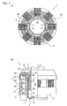
- FIGS. 1(A) and (B) are a partial plan view of a linear actuator according to the present invention, and an explanatory diagram depicting a cutaway view thereof, respectively.
- FIGS. 2(A), (B), (C), and (D) are a cross-sectional view along the line A-A' of a stator of this linear actuator, an explanatory diagram depicting a cutaway view thereof, a plan view of an inner yoke holding member for holding an inner yoke, and an explanatory diagram depicting a structural example of the inner yoke, respectively.
- FIGS. 1(A) and (B) are a partial plan view of a linear actuator according to the present invention, and an explanatory diagram depicting a cutaway view thereof, respectively.
- FIGS. 2(A), (B), (C), and (D) are a cross-sectional view along the line A-A' of a stator of this linear actuator, an explanatory diagram depicting a cutaway view thereof, a
- 3(A), (B), (C), (D), and (E) are a plan view, longitudinal sectional view, and bottom view of the movable member side of the linear actuator, as well as an explanatory diagram of poles formed by magnetization on a magnet and an enlarged plan view of the magnet holders, respectively.
- the linear actuator 1 of the present embodiment is used in a compressor device or a pump device for supplying fluids, and the actuator has a frame 11 for holding a stator side, and a movable member 5 capable of rectilinear movement along an axis line L in relation to the frame 11.
- the frame 11 is mounted on a pump case or other device, for example.
- a cylinder body 2 with a flange part 21 is held in the frame 11 on the stator side, as shown in FIGS. 2(A) and (B).
- a circular plate-shaped inner yoke holding member 23 shown in FIG. 2(C) is mounted on an outer peripheral surface of a cylindrical section 22 of the cylinder body 2.
- the inner yoke holding member 23 has eight rectilinearly extending slits 231 formed at regular angular intervals in a circumferential direction, and inner yokes 3 composed of magnetic plates are fixed in place in the inner yoke holding member 23 at positions corresponding to the slits 231. Therefore, eight inner yokes 3 are disposed at regular angular intervals in the circumferential direction.
- the inner yokes 3 are shaped as flat plates, and both opposing surfaces (outer surfaces) facing outer yokes 4 described herein below and back surfaces (inner surfaces) are flat surfaces.
- flat opposing surfaces refers to a configuration in which the entire outer surfaces of the inner yokes 3 lie in the same plane, or a configuration in which concavities 36 are formed in the outer surfaces of the inner yokes 3, and bottom surfaces of these concavities 36 are made flat as opposing surfaces 37 facing the outer yokes 4 for the purpose of improving magnetic characteristics, as shown in FIG. 2(D).
- Eight outer yokes 4 are mounted at regular angular intervals in the circumferential direction on the frame 11 in a block structure in which two gaps 9A and 9B are formed at positions separated from the opposing surfaces of the inner yokes 3 in the axial direction.
- the surfaces of the outer yokes 4 that face the inner yokes 3 are made flat.
- the outer yokes 4 are configured from two vertically aligned yoke pieces 41 and 42 with U-shaped longitudinal sections, and portions of the yoke pieces 41 and 42 that curve inside in the axial direction are formed into magnetic poles 43 and 44 that face the inner yokes 3 via the gaps.
- the two yoke pieces 41 and 42 both have a block structure wherein a plurality of magnetic thin plates with end faces directed towards the inner yokes 3 are layered in an out-of-plane direction. The advantage of this arrangement is that eddy-current loss in the outer yokes 4 is relatively small.
- a coil 8 wound around a bobbin 80 with a flat ring shape is disposed in spaces formed between the two yoke pieces 41 and 42.
- the coil 8 is a common coil wound so as to entirely encircle the eight outer yokes 4.
- the outer yokes 4 comprise first outer yoke portions 401 extending rectilinearly in the circumferential direction around the inside of the coil 8, and second outer yoke portions 402 extending rectilinearly in the circumferential direction around the outside of the coil 8.
- a cup-shaped movable member 5 shown in FIGS. 3(A), (B), and (C) is disposed in the stator thus configured.
- This movable member 5 is a molded resin article having a perfectly octagonal bottom part 51 and thin, long magnet holders 52 rising from corner portions of the bottom part 51 in the axial direction.
- Grooves 520 for inserting and fixing in place two sides of flat plate magnets 6 are formed in side surfaces of the magnet holders 52, and the two ends of the plate-shaped magnets 6 are inserted therein.
- a total of eight magnet holders 52 are formed in the movable member 5, and eight plate-shaped magnets 6 are held at regular angular intervals in the circumferential direction.
- the magnets 6 herein are Nd-Fe-B based rare-earth magnets or resin magnets, and the front and back of the magnets are magnetized with opposite polarities as shown in FIG. 3(D).
- the magnet holders 52 have a substantially triangular flat shape as seen from the axial direction, and the portions corresponding to apexes of the triangles extend in cuneiform fashion between adjacent inner yokes 3, as shown in FIG 3(E). At the same time, the portions of the magnet holders 52 that correspond to the bottoms of the triangles extend between adjacent outer yokes 4.
- Eight magnets 6 are positioned in the gaps 9A and 9B between the inner yokes 3 and outer yokes 4 in a state in which the movable member 5 thus configured is mounted on the frame 11 as shown in FIGS. 1(A) and (B). Also, the bottom part 51 of the movable member 5 serves as a fixing part for a base of a rod-shaped or cylindrical piston 50, and the piston 50 is mounted on an inner side of the cylindrical section 22 of the cylinder body 2.
- inner side surfaces of the magnets 6 are magnetized as S poles and outer side surfaces are magnetized as N poles, in which case a magnetic field shown by dotted arrows B1 and B2 in FIG. 1(B) is generated.
- a magnetic field shown by a solid arrow B3 is generated during the time the current passes from the front of the diagram to the reverse side, and the magnetic field from the magnets 6 and lines of magnetic force from the coil 8 have the same orientation on the side of the gap 9A, whereas the magnetic field from the magnets 6 and the lines of magnetic force from the coil 8 have opposite orientations on the side of the gap 9B.
- a downward force acts on the magnets 6.
- the outer yokes 4 and inner yokes 3 have flat opposing surfaces, and eight yokes of each type are disposed at regular angular intervals in the circumferential direction. It is therefore possible to generate a drive force with substantially the same magnetic efficiency as when the outer yokes 4 and inner yokes 3 have arcuate opposing surfaces, and inner yokes 3 and outer yokes 4 with such a shape can be easily produced on a mass scale. Also, flat plate magnets 6 can be used if the outer yokes 4 and inner yokes 3 have flat opposing surfaces, and such magnets 6 can be easily mass-produced as well. Consequently, according to the present invention, it is possible to provide an inexpensive linear actuator 1 that can be produced on a mass scale.
- the movable member 5 has long, thin magnet holders 52 rising in the axial direction from the corner portions of the bottom part 51, and these magnet holders 52 have substantially triangular flat shapes as seen from the axial direction, and extend between adjacent inner yokes 3 and between adjacent outer yokes 4. Therefore, it is possible to prevent the orientation, shape, and other attributes of the magnets 6 from being altered by the magnetic force of adjacent magnets 6 even if strong, flat plate magnets 6 are used, which has the advantage of making assembly easier.
- the outer yokes 4 and inner yokes 3 may also be formed from sintered soft magnetic components produced by molding and sintering materials obtained by applying resins to surfaces of pure iron powder or a powder prepared by adding trace amounts of additives to iron.
- sintered soft magnetic components have advantages in that they are commercially available under the product name FM-CM and the like from Sumitomo Electric Industries, Ltd., that various three-dimensional shapes can be readily formed with high machining precision, and that these components are isotropic, unlike magnetic thin plates. Coating the surface of the powder with a resin is also advantageous in increasing the internal resistance and markedly reducing the eddy-current loss, producing excellent high-frequency characteristics. Furthermore, sintered soft magnetic components can be easily crushed, and are therefore easy to recycle.
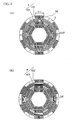
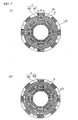
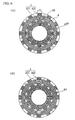
- a coil 8 wound in a circular fashion was used in the above embodiment, but it is preferable for the coil 8 to be wound in a substantially polygonal shape and to be rectilinear between the first outer yoke portions 401 and second outer yoke portions 402, such as in the case of six, eight, and twelve outer yokes 4 as shown in FIGS 4(B), 5(B), and 6(B), respectively.
- the winding width of the coil 8 is 6.138 mm if the coil 8 is wound in a circular fashion as shown in FIG. 4(A), while the winding width of the coil 8 is 7.87 mm if the coil 8 is wound in a polygonal fashion as shown in FIG. 4(B).
- the winding width of the coil 8 is 7.35 mm if the coil 8 is wound in a circular fashion as shown in FIG. 5(A), while the winding width of the coil 8 is 8.4 mm if the coil 8 is wound in a polygonal fashion as shown in FIG. 5(B).
- the winding width of the coil 8 is 7.868 mm if the coil 8 is wound in a circular fashion as shown in FIG. 6(A), while the winding width of the coil 8 is 8.4 mm if the coil 8 is wound in a polygonal fashion as shown in FIG. 6(B).
- the driving force (performance) herein is directly proportional to the value determined by the following equation.
- the value determined by the above equation is as follows when the number of yokes is six, eight, and twelve.
- the outer yokes 4 and inner yokes 3 were both held by the holding member made of the resin, but they may also be formed integrally with the holding member using insert molding or the like.
- the number of yokes may, for example, be twelve or any other number equal or greater than six.
- the number of inner yokes 3 and outer yokes 4 is preferably six to eight for the following reasons (see FIGS. 4 and 5) .
- the number of magnet holders 52 is also six to eight.
- the number of magnet holders 52 increases and the space occupied by the magnet holders 52 also increases as a result of the number of magnets 6 increasing with the increase in the number of outer yokes 4 and inner yokes 3.
- reducing the magnet holders 52 makes the magnet holders 52 incapable of withstanding the magnetic force exerted by the adjacent magnets 6 on each other because strong magnets 6 are used. Therefore, when the space occupied by the magnet holders 52 and the strength thereof are taken into account, it is better to have a smaller number of outer yokes 4 and inner yokes 3.
- the circumferential dimensions of the outer yokes 4 are determined by the number of the outer yokes 4.
- the entire length along which the outer yokes are disposed in the circumferential direction is also determined by the number of the outer yokes 4.
- the dimension in the circumferential direction is 21.5 mm
- the entire length along which the outer yokes 4 are disposed along the entire circumferential direction is 129 mm.
- the dimension in the circumferential direction is 16 mm
- the entire length along which the outer yokes 4 are disposed along the entire circumferential direction is 128 mm.
- the dimension in the circumferential direction is 10 mm
- the entire length along which the outer yokes 4 are disposed along the entire circumferential direction is 120 mm.
- the outer yokes and inner yokes have flat opposing surfaces and face each other via gaps perpendicular to the axial direction, and pluralities of both are disposed at regular angular intervals in the circumferential direction.
- drive forces can be generated with substantially the same magnetic efficiency as when the opposing surfaces of the outer yokes and inner yokes are formed into arcuate shapes.
- the movable member has magnet holders for holding both sides of the magnets in a state in which at least part thereof extends between adjacent inner yokes and between adjacent outer yokes, making it possible to accurately set the orientation or location of the magnets by the magnet holders even if the magnets attract or repel each other. For this reason, assembly is easier to accomplish. Therefore, according to the present invention, it is possible to provide an inexpensive mass-produced linear actuator.
Landscapes
- Engineering & Computer Science (AREA)
- Power Engineering (AREA)
- Mechanical Engineering (AREA)
- General Engineering & Computer Science (AREA)
- Reciprocating, Oscillating Or Vibrating Motors (AREA)
- Reciprocating Pumps (AREA)
- Compressors, Vaccum Pumps And Other Relevant Systems (AREA)
- Iron Core Of Rotating Electric Machines (AREA)
- Linear Motors (AREA)
Applications Claiming Priority (3)
| Application Number | Priority Date | Filing Date | Title |
|---|---|---|---|
| JP2002176703A JP4037695B2 (ja) | 2002-06-18 | 2002-06-18 | リニアアクチュエータ、それを用いたポンプ装置並びにコンプレッサー装置 |
| JP2002176703 | 2002-06-18 | ||
| PCT/JP2003/007694 WO2003107515A1 (ja) | 2002-06-18 | 2003-06-17 | リニアアクチュエータ、それを用いたポンプ装置並びにコンプレッサー装置 |
Publications (1)
| Publication Number | Publication Date |
|---|---|
| EP1536546A1 true EP1536546A1 (de) | 2005-06-01 |
Family
ID=29728112
Family Applications (1)
| Application Number | Title | Priority Date | Filing Date |
|---|---|---|---|
| EP03760162A Withdrawn EP1536546A1 (de) | 2002-06-18 | 2003-06-17 | Linearstellglied und pumpen- und kompressoreinrichtungen mit dem stellglied |
Country Status (7)
| Country | Link |
|---|---|
| US (1) | US6980072B2 (de) |
| EP (1) | EP1536546A1 (de) |
| JP (1) | JP4037695B2 (de) |
| CN (1) | CN100440694C (de) |
| AU (1) | AU2003244230A1 (de) |
| BR (1) | BR0311361A (de) |
| WO (1) | WO2003107515A1 (de) |
Cited By (1)
| Publication number | Priority date | Publication date | Assignee | Title |
|---|---|---|---|---|
| EP2919366A4 (de) * | 2012-11-07 | 2017-01-25 | Qingdao Haier Smart Technology R&D Co., Ltd. | Stator für einen linearverdichter und fixierverfahren dafür, lineare elektrische maschine und linearverdichter |
Families Citing this family (11)
| Publication number | Priority date | Publication date | Assignee | Title |
|---|---|---|---|---|
| KR100520072B1 (ko) * | 2003-06-19 | 2005-10-11 | 삼성전자주식회사 | 리니어 압축기 |
| KR100641112B1 (ko) * | 2004-07-28 | 2006-11-02 | 엘지전자 주식회사 | 왕복동식 압축기 및 그의 제조 방법 |
| KR100624733B1 (ko) * | 2005-05-06 | 2006-09-15 | 엘지전자 주식회사 | 리니어 모터의 아우터 코어 조립구조 |
| JP4429228B2 (ja) * | 2005-07-25 | 2010-03-10 | キヤノン株式会社 | 駆動装置 |
| JP2007065430A (ja) * | 2005-08-31 | 2007-03-15 | Mitsumi Electric Co Ltd | カメラ用アクチュエータ |
| JP2007068373A (ja) * | 2005-09-02 | 2007-03-15 | Nidec Sankyo Corp | リニアアクチュエータ、ポンプ装置、およびコンプレッサー装置 |
| BRPI0615706A2 (pt) * | 2006-09-14 | 2011-05-24 | Norimasa Okamoto | gerador |
| JP5347218B2 (ja) * | 2006-10-18 | 2013-11-20 | 株式会社安川電機 | 大推力リニアモータユニット |
| WO2008084964A2 (en) * | 2007-01-08 | 2008-07-17 | Lg Electronics, Inc. | Linear motor for linear compresser |
| JP4992444B2 (ja) * | 2007-02-02 | 2012-08-08 | ミツミ電機株式会社 | カメラモジュール |
| CN105099010B (zh) * | 2014-05-08 | 2018-12-18 | 青岛海尔智能技术研发有限公司 | 一种定子结构以及应用该定子结构的线性压缩机 |
Family Cites Families (7)
| Publication number | Priority date | Publication date | Assignee | Title |
|---|---|---|---|---|
| JP2742184B2 (ja) | 1992-09-14 | 1998-04-22 | 積水化成品工業株式会社 | プラスチック回収用押出機 |
| US6077054A (en) * | 1997-12-23 | 2000-06-20 | Samsung Electronics Co., Ltd. | Stator of linear compressor |
| JP2000209833A (ja) * | 1999-01-07 | 2000-07-28 | Tamagawa Seiki Co Ltd | リニアアクチュエ―タ |
| US6365993B1 (en) | 2000-04-07 | 2002-04-02 | Eaton Corporation | Round linear actuator utilizing flat permanent magnets |
| JP2002034225A (ja) * | 2000-07-19 | 2002-01-31 | Sanyo Electric Co Ltd | 磁石可動型リニアモータ |
| KR100386277B1 (ko) * | 2001-04-04 | 2003-06-02 | 엘지전자 주식회사 | 왕복동식 압축기 |
| JP4149147B2 (ja) * | 2001-07-19 | 2008-09-10 | 松下電器産業株式会社 | リニア圧縮機 |
-
2002
- 2002-06-18 JP JP2002176703A patent/JP4037695B2/ja not_active Expired - Fee Related
-
2003
- 2003-06-17 BR BR0311361-2A patent/BR0311361A/pt not_active IP Right Cessation
- 2003-06-17 WO PCT/JP2003/007694 patent/WO2003107515A1/ja not_active Ceased
- 2003-06-17 US US10/515,893 patent/US6980072B2/en not_active Expired - Fee Related
- 2003-06-17 EP EP03760162A patent/EP1536546A1/de not_active Withdrawn
- 2003-06-17 CN CNB038144875A patent/CN100440694C/zh not_active Expired - Fee Related
- 2003-06-17 AU AU2003244230A patent/AU2003244230A1/en not_active Abandoned
Non-Patent Citations (1)
| Title |
|---|
| See references of WO03107515A1 * |
Cited By (1)
| Publication number | Priority date | Publication date | Assignee | Title |
|---|---|---|---|---|
| EP2919366A4 (de) * | 2012-11-07 | 2017-01-25 | Qingdao Haier Smart Technology R&D Co., Ltd. | Stator für einen linearverdichter und fixierverfahren dafür, lineare elektrische maschine und linearverdichter |
Also Published As
| Publication number | Publication date |
|---|---|
| BR0311361A (pt) | 2005-03-01 |
| US6980072B2 (en) | 2005-12-27 |
| US20050206486A1 (en) | 2005-09-22 |
| JP2004023911A (ja) | 2004-01-22 |
| CN100440694C (zh) | 2008-12-03 |
| CN1663100A (zh) | 2005-08-31 |
| WO2003107515A1 (ja) | 2003-12-24 |
| AU2003244230A8 (en) | 2003-12-31 |
| JP4037695B2 (ja) | 2008-01-23 |
| AU2003244230A1 (en) | 2003-12-31 |
Similar Documents
| Publication | Publication Date | Title |
|---|---|---|
| US7382067B2 (en) | Linear actuator | |
| CN1316720C (zh) | 具有换向器马达的动力工具 | |
| US6946754B2 (en) | Linear motor and linear compressor | |
| US7501724B2 (en) | Movable assembly for cylinder type linear motor | |
| CN103222169B (zh) | 电磁发电机 | |
| US6980072B2 (en) | Linear actuator, and pump and compressor devices using the actuator | |
| JP2006222131A (ja) | 永久磁石体 | |
| NZ554646A (en) | Traction drive for elevator | |
| US20040061384A1 (en) | Linear electric machine | |
| JP2000236653A (ja) | リニアモータの固定子およびその製造方法 | |
| KR20160087872A (ko) | 전기 모터 | |
| US6700286B2 (en) | Stator structure of reciprocating motor | |
| EP3324526A1 (de) | Magnetfelderzeugungselement und motor damit | |
| JP2020156259A (ja) | 筒型リニアモータ | |
| KR100518780B1 (ko) | 선형 엑츄에이터를 위한 가동자 | |
| JP3851012B2 (ja) | リニア振動モータ | |
| JP4551684B2 (ja) | シリンダ型リニアモータ | |
| KR20050016556A (ko) | 리니어 액추에이터, 그것을 사용한 펌프장치 및 컴프레서장치 | |
| JP2001231239A (ja) | 電磁往復駆動機構 | |
| KR102921091B1 (ko) | 영구자석 회전기의 회전자 | |
| JPH0644385U (ja) | 可動磁石式アクチュエータ | |
| JP2011244645A (ja) | リニアモータ | |
| JP2004040951A (ja) | リニアアクチュエータ、それを用いたポンプ装置並びにコンプレッサー装置 |
Legal Events
| Date | Code | Title | Description |
|---|---|---|---|
| PUAI | Public reference made under article 153(3) epc to a published international application that has entered the european phase |
Free format text: ORIGINAL CODE: 0009012 |
|
| 17P | Request for examination filed |
Effective date: 20050103 |
|
| AK | Designated contracting states |
Kind code of ref document: A1 Designated state(s): AT BE BG CH CY CZ DE DK EE ES FI FR GB GR HU IE IT LI LU MC NL PT RO SE SI SK TR |
|
| AX | Request for extension of the european patent |
Extension state: AL LT LV MK |
|
| DAX | Request for extension of the european patent (deleted) | ||
| RAP1 | Party data changed (applicant data changed or rights of an application transferred) |
Owner name: SHARP KABUSHIKI KAISHA Owner name: NIDEC SANKYO CORPORATION |
|
| RIN1 | Information on inventor provided before grant (corrected) |
Inventor name: UEDA, KAZUHIKO Inventor name: TANAKA, SHOHZOH Inventor name: YUMITA, YUKINOBU,SANKYO SEIKI MFG. CO., LTD. |
|
| STAA | Information on the status of an ep patent application or granted ep patent |
Free format text: STATUS: THE APPLICATION IS DEEMED TO BE WITHDRAWN |
|
| 18D | Application deemed to be withdrawn |
Effective date: 20090701 |