EP1536105A1 - Clausius-rankine-kreislaufsystem - Google Patents
Clausius-rankine-kreislaufsystem Download PDFInfo
- Publication number
- EP1536105A1 EP1536105A1 EP03771275A EP03771275A EP1536105A1 EP 1536105 A1 EP1536105 A1 EP 1536105A1 EP 03771275 A EP03771275 A EP 03771275A EP 03771275 A EP03771275 A EP 03771275A EP 1536105 A1 EP1536105 A1 EP 1536105A1
- Authority
- EP
- European Patent Office
- Prior art keywords
- steam
- expander
- pressure
- flow rate
- working medium
- Prior art date
- Legal status (The legal status is an assumption and is not a legal conclusion. Google has not performed a legal analysis and makes no representation as to the accuracy of the status listed.)
- Withdrawn
Links
- 239000012071 phase Substances 0.000 claims abstract description 28
- 239000007791 liquid phase Substances 0.000 claims abstract description 7
- 238000006073 displacement reaction Methods 0.000 claims description 5
- 238000010438 heat treatment Methods 0.000 claims description 5
- XLYOFNOQVPJJNP-UHFFFAOYSA-N water Substances O XLYOFNOQVPJJNP-UHFFFAOYSA-N 0.000 description 37
- 230000004043 responsiveness Effects 0.000 description 8
- 238000010586 diagram Methods 0.000 description 7
- 230000001276 controlling effect Effects 0.000 description 5
- 230000007423 decrease Effects 0.000 description 5
- 238000001816 cooling Methods 0.000 description 4
- 239000007789 gas Substances 0.000 description 4
- 230000000593 degrading effect Effects 0.000 description 3
- 238000000034 method Methods 0.000 description 3
- 230000001105 regulatory effect Effects 0.000 description 3
- 239000002826 coolant Substances 0.000 description 2
- 239000002918 waste heat Substances 0.000 description 2
- 230000003247 decreasing effect Effects 0.000 description 1
- 230000001419 dependent effect Effects 0.000 description 1
- 238000011084 recovery Methods 0.000 description 1
Images


Classifications
-
- F—MECHANICAL ENGINEERING; LIGHTING; HEATING; WEAPONS; BLASTING
- F01—MACHINES OR ENGINES IN GENERAL; ENGINE PLANTS IN GENERAL; STEAM ENGINES
- F01K—STEAM ENGINE PLANTS; STEAM ACCUMULATORS; ENGINE PLANTS NOT OTHERWISE PROVIDED FOR; ENGINES USING SPECIAL WORKING FLUIDS OR CYCLES
- F01K13/00—General layout or general methods of operation of complete plants
- F01K13/02—Controlling, e.g. stopping or starting
-
- F—MECHANICAL ENGINEERING; LIGHTING; HEATING; WEAPONS; BLASTING
- F01—MACHINES OR ENGINES IN GENERAL; ENGINE PLANTS IN GENERAL; STEAM ENGINES
- F01K—STEAM ENGINE PLANTS; STEAM ACCUMULATORS; ENGINE PLANTS NOT OTHERWISE PROVIDED FOR; ENGINES USING SPECIAL WORKING FLUIDS OR CYCLES
- F01K23/00—Plants characterised by more than one engine delivering power external to the plant, the engines being driven by different fluids
- F01K23/02—Plants characterised by more than one engine delivering power external to the plant, the engines being driven by different fluids the engine cycles being thermally coupled
- F01K23/06—Plants characterised by more than one engine delivering power external to the plant, the engines being driven by different fluids the engine cycles being thermally coupled combustion heat from one cycle heating the fluid in another cycle
- F01K23/065—Plants characterised by more than one engine delivering power external to the plant, the engines being driven by different fluids the engine cycles being thermally coupled combustion heat from one cycle heating the fluid in another cycle the combustion taking place in an internal combustion piston engine, e.g. a diesel engine
-
- F—MECHANICAL ENGINEERING; LIGHTING; HEATING; WEAPONS; BLASTING
- F01—MACHINES OR ENGINES IN GENERAL; ENGINE PLANTS IN GENERAL; STEAM ENGINES
- F01K—STEAM ENGINE PLANTS; STEAM ACCUMULATORS; ENGINE PLANTS NOT OTHERWISE PROVIDED FOR; ENGINES USING SPECIAL WORKING FLUIDS OR CYCLES
- F01K23/00—Plants characterised by more than one engine delivering power external to the plant, the engines being driven by different fluids
- F01K23/02—Plants characterised by more than one engine delivering power external to the plant, the engines being driven by different fluids the engine cycles being thermally coupled
- F01K23/06—Plants characterised by more than one engine delivering power external to the plant, the engines being driven by different fluids the engine cycles being thermally coupled combustion heat from one cycle heating the fluid in another cycle
- F01K23/10—Plants characterised by more than one engine delivering power external to the plant, the engines being driven by different fluids the engine cycles being thermally coupled combustion heat from one cycle heating the fluid in another cycle with exhaust fluid of one cycle heating the fluid in another cycle
- F01K23/101—Regulating means specially adapted therefor
Definitions
- the present invention relates to a Rankine cycle system that includes an evaporator for heating a liquid-phase working medium with exhaust gas of an engine so as to generate a gas-phase working medium, and a displacement type expander for converting the thermal energy of the gas-phase working medium generated in the evaporator into mechanical energy.
- Japanese Patent Application Laid-open No. 2000-345835 discloses a waste heat recovery system for driving a turbine by heating coolant vapor of a cooling system of an engine with waste heat of the engine, in which the thermal efficiency is enhanced by optimally controlling the pressure or temperature of a cooling path according to engine running conditions. Specifically, the value for a target pressure of the cooling path is lowered as the engine rotational speed and the engine load increase, and the amount discharged from a coolant circulation pump, etc. is controlled so that the actual pressure coincides with the target pressure.
- the efficiency of the evaporator and the efficiency of the expander of a Rankine cycle system depend on the steam temperature; in order to maximize the total efficiency of the two it is necessary to control the steam temperature at an optimum steam temperature, and if the steam temperature deviates from the optimum steam temperature as a result of the amount of water supplied being changed so as to make the steam pressure coincide with the target steam pressure, there is the problem that the total efficiency of the evaporator and the expander might be degraded.
- the present invention has been accomplished under the above-mentioned circumstances, and it is an object thereof to control with high precision the pressure of a gas-phase working medium at the inlet of an expander in a Rankine cycle system at a target pressure without changing the amount of liquid-phase working medium supplied to an evaporator.
- a Rankine cycle system that includes an evaporator for heating a liquid-phase working medium with exhaust gas of an engine so as to generate a gas-phase working medium, and a displacement type expander for converting the thermal energy of the gas-phase working medium generated in the evaporator into mechanical energy, characterized in that, in order to make the pressure of the gas-phase working medium at the inlet of the expander coincide with a target pressure, the system includes control means for calculating a feedforward value on the basis of the target pressure and the flow rate of the gas-phase working medium at the outlet of the evaporator, calculating a feedback value by multiplying a deviation of the pressure of the gas-phase working medium at the inlet of the expander from the target pressure by a feedback gain calculated on the basis of the flow rate of the gas-phase working medium, and controlling the rotational speed of the expander on the basis of the result of addition/subtraction of the feedforward value and the feedback value.
- the feedforward value is calculated on the basis of the flow rate of the gas-phase working medium at the outlet of the evaporator and the target pressure of the gas-phase working medium at the inlet of the expander
- the feedback value is calculated by multiplying the deviation of the pressure of the gas-phase working medium at the inlet of the expander from the target pressure by the feedback gain calculated on the basis of the flow rate of the gas-phase working medium
- the rotational speed of the expander is controlled on the basis of the result of addition/subtraction of the feedforward value and the feedback value
- a controller 20 of embodiments corresponds to the control means of the present invention.
- FIG. 1 to FIG. 12 show a first embodiment of the present invention
- FIG. 1 is a block diagram of a Rankine cycle system and a control system therefor
- FIG. 2 is a map for looking up a target steam pressure from a steam energy and a target steam temperature
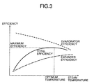
- FIG. 3 is a graph showing the relationship between optimum steam temperature and maximum total efficiency of an evaporator and an expander
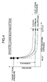
- FIG. 4 is a graph showing the relationship between the pressure at the inlet and the pressure at the outlet of the expander
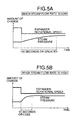
- FIG. 5A and FIG. 5B are graphs showing changes in steam pressure when the rotational speed of the expander is changed stepwise
- FIG. 6A and FIG. 6B are diagrams showing convergence of the steam pressure when the feedback gain is fixed
- FIG. 7B are diagrams showing convergence of the steam pressure when the feedback gain is variable
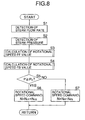
- FIG. 8 is a flowchart of a steam pressure control main routine
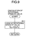
- FIG. 9 is a flowchart of a subroutine of step S3 of the main routine
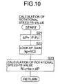
- FIG. 10 is a flowchart of a subroutine of step S4 of the main routine
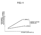
- FIG. 11 is a map for looking up a feedforward value N FF for the rotational speed of the expander from a steam flow rate Q and a target steam pressure P o
- FIG. 12 is a table for looking up a feedback gain kp from the steam flow rate Q.
- FIG. 13 to FIG. 16 show a second embodiment of the present invention.
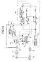
- FIG. 13 is a block diagram of a Rankine cycle system and a control system therefor
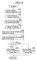
- FIG. 14 is a flowchart of a steam pressure control main routine
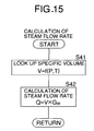
- FIG. 15 is a flowchart of a subroutine of step S34 of the main routine
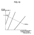
- FIG. 16 is a map for looking up a steam specific volume V from a steam pressure P and a steam temperature T.
- FIG. 17 to FIG. 20 show a third embodiment of the present invention
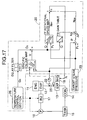
- FIG. 17 is a block diagram of a Rankine cycle system and a control system therefor
- FIG. 18 is a flowchart of a steam pressure control main routine
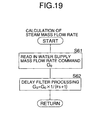
- FIG. 19 is a flowchart of a subroutine of step S53 of the main routine
- FIG. 20 is a flowchart of a subroutine of step S54 of the main routine.
- FIG. 21 to FIG. 25 show a fourth embodiment of the present invention.
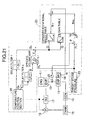
- FIG. 21 is a block diagram of a Rankine cycle system and a control system therefor
- FIG. 22 is a flowchart of a steam pressure control main routine
- FIG. 23 is a flowchart of a subroutine of step S72 of the main routine
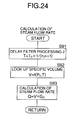
- FIG. 24 is a flowchart of a subroutine of step S73 of the main routine
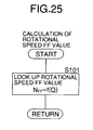
- FIG. 25 is a flowchart of a subroutine of step S74 of the main routine.
- FIG. 1 to FIG. 12 show a first embodiment of the present invention.
- a Rankine cycle system for recovering the thermal energy of exhaust gas of a vehicle engine 11 is formed from an evaporator 12 for heating a liquid-phase working medium (water) with the exhaust gas of the engine 11 and generating a high temperature, high pressure gas-phase working medium (steam), a displacement type expander 13 for converting the thermal energy of the high temperature, high pressure steam generated in the evaporator 12 into mechanical energy, a condenser 14 for cooling the steam discharged from the expander 13 and condensing it into water, a tank 15 for storing water discharged from the condenser 14, a water supply pump 16 for drawing up water out of the tank 15, and an injector 17 for injecting water drawn up by the water supply pump 16 into the evaporator 12, the above being arranged in a closed circuit.
- a motor/generator 18 connected to the expander 13 is disposed between the engine 11 and driven wheels; the motor/generator 18 can be made to function as a motor so as to assist the output of the engine 11, and when the vehicle is being decelerated the motor/generator 18 can be made to function as a generator so as to recover the kinetic energy of the vehicle as electrical energy.
- the motor/generator 18 may be connected to the expander 13 alone, and then exhibits only the function of generating electrical energy.
- the rotational speed of the expander 13 is controlled by regulating the load (amount of electric power generated) of the motor/generator 18 so as to regulate the load imposed on the expander 13 by the motor/generator 18.
- Input into a controller 20 are a signal from a steam flow rate sensor 21 for detecting a steam flow rate at the outlet of the evaporator 12, and a signal from a steam pressure sensor 22 for detecting a steam pressure at the inlet of the expander 13.
- the controller 20 includes target steam pressure setting means 23 for setting a target steam pressure, which is a target value for the steam pressure at the inlet of the expander 13.
- the target steam pressure setting means 23 looks up the target steam pressure on the basis of a target steam temperature and a steam energy (steam flow rate).
- the steam temperature at the outlet of the evaporator 12 is controlled by regulating the amount of water supplied from the injector 17 or the water supply pump 16 to the evaporator 12 so that the steam temperature coincides with the temperature at which the total efficiency of the evaporator 12 and the expander 13 becomes a maximum (that is, an optimum steam temperature). That is, as shown in FIG.
- the efficiency of the evaporator 12 and the efficiency of the expander 13 change depending on the steam temperature; when the steam temperature increases, the efficiency of the evaporator 12 decreases and the efficiency of the expander 13 increases, whereas when the steam temperature decreases, the efficiency of the evaporator 12 increases and the efficiency of the expander 13 decreases.
- the reason why the steam pressure at the inlet of the expander 13 is controlled at the target steam pressure is as follows. That is, as shown in FIG. 4, if the steam pressure at the inlet of the expander 13 coincides with the target steam pressure, the steam pressure at the outlet of the expander 13 is a pressure that is commensurate with an expansion ratio of the expander 13, but if the inlet steam pressure is too high, since the steam discharged from the outlet of the expander 13 has surplus energy remaining, there is the problem that the energy is wastefully discarded. On the other hand, if the inlet steam pressure is too low, the pressure of the steam discharged from the outlet of the expander 13 becomes negative, and there is the problem that the expander 13 carries out negative work, thus degrading the efficiency.
- the load imposed on the expander 13 by the motor/generator 18 may be regulated so as to control the rotational speed of the expander 13. As shown in FIG. 5A and FIG. 5B, when the rotational speed of the expander 13 is decreased, the steam pressure increases, whereas when the rotational speed of the expander 13 is increased, the steam pressure decreases.
- the responsiveness with which the steam pressure changes depends on the steam flow rate; when the steam flow rate is low, the responsiveness is low, and at least 100 seconds is needed for the steam pressure to reach a steady state, whereas when the steam flow rate is high, the responsiveness is high, and it takes no more than 10 seconds for the steam pressure to reach the steady state.
- a Ti value is controlled so as to coincide with a target amount of water supplied by detecting a difference in pressure before and after the injector 17, or if the rotational speed of the water supply pump 16 is controlled by detecting a discharge pressure from the water supply pump 16, even when the rotational speed of the expander 13 changes, it is possible to maintain the amount of water supplied to the evaporator 12 constant, thereby enabling the steam temperature at the outlet of the evaporator 11 to be maintained at the optimum steam temperature.
- the gist of the present invention is that, when the rotational speed of the expander 13 is feedback-controlled so that the steam pressure at the inlet of the expander 13 coincides with a target steam pressure, the feedback gain is changed according to the steam flow rate. Specific details thereof are explained below with reference to the block diagram of FIG. 1 and the flowcharts of FIG. 8 to FIG. 10.
- step S1 of the flowchart of FIG. 8 the steam flow rate sensor 21 detects a steam flow rate Q at the outlet of the evaporator 12, in step S2 the steam pressure sensor 22 detects a steam pressure P at the inlet of the expander 13, and in step S3 a feedforward value N FF for the rotational speed of the expander 13 is then calculated. That is, in step S11 of the flowchart of FIG. 9 the feedforward value N FF for the rotational speed of the expander 13 is looked up from the map of FIG. 11 using as parameters the steam flow rate Q and the target steam pressure P o . As is clear from FIG. 11, the lower the steam flow rate Q and the greater the target steam pressure P o , the smaller the feedforward value N FF , and the higher the steam flow rate Q and the smaller the target steam pressure P o , the larger the feedforward value N FF .
- step S5 if in step S5 the steam pressure P is equal to or greater than the target steam pressure P o , then in step S6 the feedback value N FB is added to the feedforward value N FF for the rotational speed of the expander 13, thus calculating a rotational speed command value N for the expander 13, and if in step S5 the steam pressure P is less than the target steam pressure P o , then in step S7 the feedback value N FB is subtracted from the feedforward value N FF for the rotational speed of the expander 13, thus calculating the rotational speed command value N for the expander 13.
- FIG. 13 to FIG. 16 show a second embodiment of the present invention.
- the second embodiment does not include the steam flow rate sensor 21 of the first embodiment (see FIG. 1), but instead includes a water supply amount sensor 24 on the inlet side of an evaporator 12, and a steam temperature sensor 25 on the inlet side of an expander 13.
- the steam flow rate Q is directly detected by the steam flow rate sensor 21
- a steam flow rate Q is calculated from a steam pressure P detected by a steam pressure sensor 22, a water supply mass flow rate Gw detected by the water supply amount sensor 24, and a steam temperature T detected by the steam temperature sensor 25, and the other arrangements and operations are the same as those of the first embodiment.
- step S31 of the flowchart of FIG. 14 the steam temperature sensor 25 detects the steam temperature T at the inlet of the expander 13
- step S32 the steam pressure sensor 22 detects the steam pressure P at the inlet of the expander 13
- step S33 the water supply amount sensor 24 detects the water supply mass flow rate Gw to the evaporator 12.
- step S34 the steam flow rate Q to the expander 13 is calculated without using the steam flow rate sensor 21. That is, in step S41 of the flowchart of FIG. 15 a steam specific volume V is looked up in the map of FIG. 16 using the steam temperature T and the steam pressure P as parameters. As is clear from FIG. 16, the smaller the steam pressure P and the higher the steam temperature T, the greater the steam specific volume V. In the subsequent step S42 the steam flow rate Q is calculated by multiplying the specific volume V by the water supply mass flow rate Gw detected by the water supply amount sensor 24.
- FIG. 17 to FIG. 20 show a third embodiment of the present invention.
- the third embodiment does not include the water supply amount sensor 24 of the second embodiment (see FIG. 13), but instead a controller 20 is equipped with a temperature control section 26.
- a controller 20 is equipped with a temperature control section 26.
- the water supply amount sensor 24 detects the water supply mass flow rate Gw
- a steam mass flow rate Gs which corresponds to the water supply mass flow rate Gw, is calculated from a water supply mass flow rate command Go output by the temperature control section 26, and the other arrangements and operations are the same as those of the second embodiment.
- step S51 of the flowchart of FIG. 18 a steam temperature sensor 25 detects a steam temperature T at the inlet of an expander 13, in step S52 a steam pressure sensor 22 detects a steam pressure P at the inlet of the expander 13 and, furthermore, in step S53 a steam mass flow rate Gs is calculated.
- step S61 of the flowchart of FIG. 19 the water supply mass flow rate command G o output by the temperature control section 26 for controlling the steam temperature T by controlling the amount of water supplied by an injector 17 or a water supply pump 16 is read in, and in step S62 the water supply mass flow rate command G o is subjected to delay filter processing so as to calculate the steam mass flow rate Gs.
- This delay filter processing is for compensating for a time delay from the output of the water supply mass flow rate command G o by the temperature control section 26 to the actual generation of steam by the evaporator 12.
- step S54 of the flowchart of FIG. 18 a steam flow rate Q is calculated.
- a subroutine of this step S54 is shown in FIG. 20; the flowchart of FIG. 20 is substantially the same as the flowchart of FIG. 15 of the second embodiment, and the water supply mass flow rate Gw of the second embodiment is replaced by the substantially identical steam mass flow rate Gs.
- FIG. 21 to FIG. 25 show a fourth embodiment of the present invention.
- the fourth embodiment does not include the steam temperature sensor 25 of the third embodiment (see FIG. 13), but instead a temperature control section 26 of a controller 20 outputs a steam temperature command T o in addition to a water supply mass flow rate command G o .
- a target steam pressure P o and a steam temperature T obtained by subjecting the steam temperature command T o to delay processing using a delay filter 2 are input into a specific volume map.
- a steam specific volume V looked up therein is multiplied by a steam mass flow rate Gs to calculate a steam flow rate Q.
- the steam specific volume V is shown by replacing the 'steam pressure P' of the abscissa in FIG. 16 with the 'target steam pressure P o '.
- step S71 of the flowchart of FIG. 22 a steam pressure sensor 22 detects a steam pressure P at the inlet of the expander 13, and in step S72 the steam mass flow rate Gs is calculated.
- the flowchart of FIG. 23, which is a subroutine of step S72, is substantially the same as the flowchart of FIG. 19 of the third embodiment except that a time constant ⁇ is defined as a first time constant ⁇ 1 in order to differentiate it from a second time constant ⁇ 2, which will be described later.
- step S73 of the flowchart of FIG. 22 the steam flow rate Q is calculated.
- a subroutine of this step S73 is shown in FIG. 24; in step S91 of the flowchart of FIG. 24 the steam temperature command To output by the temperature control section 26 is subjected to delay processing using the delay filter 2 so as to calculate the steam temperature T, and in step S92 the steam temperature T and the target steam pressure P o output by target steam pressure setting means 23 are applied to the specific volume map so as to look up the steam specific volume V.
- step S93 the steam mass flow rate Gs output by a delay filter 1 is multiplied by the steam specific volume V so as to calculate the steam flow rate Q.
- this expander rotational speed table does not use the target steam pressure P o as a parameter, but during the process of calculating the steam flow rate Q the target steam pressure P o is applied to the specific volume map, and as a result the target steam pressure P o is taken into consideration.
- the calculated feedforward value N FF for the rotational speed of the expander 13 looked up using the steam flow rate Q is proportional to the steam flow rate Q regardless of the steam temperature and the steam pressure; in practice it might not be precisely proportional to the steam flow rate Q due to the influence of steam leakage, etc., and such an error is compensated for by feedback control of the rotational speed of the expander 13.
- the working medium is not limited to water (steam), and another appropriate working medium may be employed.
Landscapes
- Engineering & Computer Science (AREA)
- Chemical & Material Sciences (AREA)
- Combustion & Propulsion (AREA)
- Mechanical Engineering (AREA)
- General Engineering & Computer Science (AREA)
- Control Of Turbines (AREA)
- Engine Equipment That Uses Special Cycles (AREA)
- Control Of Steam Boilers And Waste-Gas Boilers (AREA)
Applications Claiming Priority (3)
| Application Number | Priority Date | Filing Date | Title |
|---|---|---|---|
| JP2002216425A JP3901609B2 (ja) | 2002-07-25 | 2002-07-25 | ランキンサイクル装置 |
| JP2002216425 | 2002-07-25 | ||
| PCT/JP2003/009222 WO2004011777A1 (ja) | 2002-07-25 | 2003-07-22 | ランキンサイクル装置 |
Publications (2)
| Publication Number | Publication Date |
|---|---|
| EP1536105A1 true EP1536105A1 (de) | 2005-06-01 |
| EP1536105A4 EP1536105A4 (de) | 2005-11-23 |
Family
ID=31184577
Family Applications (1)
| Application Number | Title | Priority Date | Filing Date |
|---|---|---|---|
| EP03771275A Withdrawn EP1536105A4 (de) | 2002-07-25 | 2003-07-22 | Clausius-rankine-kreislaufsystem |
Country Status (5)
| Country | Link |
|---|---|
| US (1) | US20060101821A1 (de) |
| EP (1) | EP1536105A4 (de) |
| JP (1) | JP3901609B2 (de) |
| AU (1) | AU2003248085A1 (de) |
| WO (1) | WO2004011777A1 (de) |
Families Citing this family (14)
| Publication number | Priority date | Publication date | Assignee | Title |
|---|---|---|---|---|
| EP1701005A1 (de) * | 2005-02-21 | 2006-09-13 | Siemens Aktiengesellschaft | Verfahren und Vorrichtung zur Berechnung energie- und verfahrenstechnischer Prozesse |
| JP4801810B2 (ja) * | 2006-05-30 | 2011-10-26 | 株式会社デンソー | 廃熱利用装置を備える冷凍装置 |
| US7950230B2 (en) | 2007-09-14 | 2011-05-31 | Denso Corporation | Waste heat recovery apparatus |
| DE102007062580A1 (de) * | 2007-12-22 | 2009-06-25 | Daimler Ag | Verfahren zur Rückgewinnung einer Verlustwärme einer Verbrennungskraftmaschine |
| EP2249017B1 (de) * | 2008-02-14 | 2013-03-27 | Sanden Corporation | Abwärme nutzende vorrichtung für einen verbrennungsmotor |
| JP5118578B2 (ja) * | 2008-08-20 | 2013-01-16 | サンデン株式会社 | 内燃機関の廃熱利用装置 |
| DE102010056272A1 (de) * | 2010-12-24 | 2012-06-28 | Robert Bosch Gmbh | Abwärmenutzungsanlage |
| JP5609707B2 (ja) * | 2011-02-22 | 2014-10-22 | トヨタ自動車株式会社 | ランキンサイクルシステムの制御装置 |
| JP5621721B2 (ja) * | 2011-06-30 | 2014-11-12 | 株式会社豊田自動織機 | ランキンサイクル |
| CN104246195B (zh) * | 2012-04-23 | 2016-09-07 | 丰田自动车株式会社 | 热输送装置 |
| CN102748080B (zh) * | 2012-07-03 | 2014-12-10 | 山东电力研究院 | 基于主蒸汽压力变化的火电机组负荷控制方法 |
| JP6021637B2 (ja) * | 2012-12-28 | 2016-11-09 | 三菱重工業株式会社 | 発電システム、発電方法 |
| SE541953C2 (en) * | 2016-07-12 | 2020-01-14 | Scania Cv Ab | A method for controlling a waste heat recovery system and such a waste heat recovery system |
| JP2019019797A (ja) * | 2017-07-20 | 2019-02-07 | パナソニック株式会社 | 熱電併給システム及び熱電併給システムの運転方法 |
Family Cites Families (6)
| Publication number | Priority date | Publication date | Assignee | Title |
|---|---|---|---|---|
| US3942327A (en) * | 1972-05-05 | 1976-03-09 | Thermo Electron Corporation | Control system for external combustion engine |
| US3906731A (en) * | 1973-01-24 | 1975-09-23 | Lear Motors Corp | Control system for vapor engines |
| US4358929A (en) * | 1974-04-02 | 1982-11-16 | Stephen Molivadas | Solar power system |
| US4039846A (en) * | 1975-08-18 | 1977-08-02 | Allied Chemical Corporation | Control of a steam-heating power plant |
| US4117344A (en) * | 1976-01-02 | 1978-09-26 | General Electric Company | Control system for a rankine cycle power unit |
| JP2000345835A (ja) * | 1999-06-07 | 2000-12-12 | Nissan Motor Co Ltd | 内燃機関 |
-
2002
- 2002-07-25 JP JP2002216425A patent/JP3901609B2/ja not_active Expired - Fee Related
-
2003
- 2003-07-22 US US10/522,063 patent/US20060101821A1/en not_active Abandoned
- 2003-07-22 AU AU2003248085A patent/AU2003248085A1/en not_active Abandoned
- 2003-07-22 EP EP03771275A patent/EP1536105A4/de not_active Withdrawn
- 2003-07-22 WO PCT/JP2003/009222 patent/WO2004011777A1/ja not_active Ceased
Non-Patent Citations (2)
| Title |
|---|
| No further relevant documents disclosed * |
| See also references of WO2004011777A1 * |
Also Published As
| Publication number | Publication date |
|---|---|
| JP3901609B2 (ja) | 2007-04-04 |
| US20060101821A1 (en) | 2006-05-18 |
| WO2004011777A1 (ja) | 2004-02-05 |
| EP1536105A4 (de) | 2005-11-23 |
| AU2003248085A1 (en) | 2004-02-16 |
| JP2004060462A (ja) | 2004-02-26 |
Similar Documents
| Publication | Publication Date | Title |
|---|---|---|
| EP1536105A1 (de) | Clausius-rankine-kreislaufsystem | |
| US20060254276A1 (en) | Rankine cycle system | |
| CN100445536C (zh) | 燃料气体加热控制装置和设置有该燃料气体加热控制装置的燃气轮机发电设备 | |
| JP2008057611A (ja) | 油圧ユニットおよび油圧ユニットにおけるモータの速度制御方法 | |
| US20060086091A1 (en) | Rankine cycle apparatus | |
| JPH0333495A (ja) | 復水ポンプ制御装置 | |
| JP4375208B2 (ja) | 燃料電池の出力制限装置 | |
| KR101818021B1 (ko) | 증기 터빈의 단기간 출력 상승을 조절하기 위한 조절 방법 | |
| JP2002280036A (ja) | 燃料電池の冷却制御装置 | |
| CN104685426B (zh) | 用于热电厂中的控制和故障分析的优化的方法 | |
| JPH05222906A (ja) | 排熱利用発電プラントの制御装置 | |
| US20180156073A1 (en) | System and method for fast startup of a combined cycle power plant | |
| US20060168963A1 (en) | Rankine cycle system | |
| JP3660757B2 (ja) | コンバインドサイクル発電プラントの制御装置 | |
| US20060179841A1 (en) | Rankine cycle system | |
| JP7075861B2 (ja) | ハイブリッド発電システム、及び、ハイブリッド発電システムの制御方法 | |
| JPH0819873A (ja) | 抵抗溶接装置および抵抗溶接方法 | |
| JP2019039371A (ja) | 廃熱回収装置 | |
| JP4284698B2 (ja) | ガスタービンへの噴射蒸気流量制御方法 | |
| US20060174623A1 (en) | Vehicular rankine cycle system | |
| JPH08284616A (ja) | 複合サイクル発電プラントの負荷制御装置 | |
| JP2006037863A (ja) | 建設機械の冷却装置 | |
| JP3374745B2 (ja) | プロセス制御装置及びその制御方法 | |
| JP2000248904A (ja) | 火力発電プラントの出力制御方法 | |
| JP2960607B2 (ja) | 熱電併給装置 |
Legal Events
| Date | Code | Title | Description |
|---|---|---|---|
| PUAI | Public reference made under article 153(3) epc to a published international application that has entered the european phase |
Free format text: ORIGINAL CODE: 0009012 |
|
| 17P | Request for examination filed |
Effective date: 20050111 |
|
| AK | Designated contracting states |
Kind code of ref document: A1 Designated state(s): AT BE BG CH CY CZ DE DK EE ES FI FR GB GR HU IE IT LI LU MC NL PT RO SE SI SK TR |
|
| AX | Request for extension of the european patent |
Extension state: AL LT LV MK |
|
| DAX | Request for extension of the european patent (deleted) | ||
| RBV | Designated contracting states (corrected) |
Designated state(s): DE GB |
|
| A4 | Supplementary search report drawn up and despatched |
Effective date: 20051007 |
|
| GRAP | Despatch of communication of intention to grant a patent |
Free format text: ORIGINAL CODE: EPIDOSNIGR1 |
|
| RIN1 | Information on inventor provided before grant (corrected) |
Inventor name: IBARAKI,S.KABUSHIKI KAISHA HONDA GIJUTSUKENKYUSHO Inventor name: SATO, A.KABUSHIKI KAISHA HONDA GIJUTSU KENKYUSHO |
|
| STAA | Information on the status of an ep patent application or granted ep patent |
Free format text: STATUS: THE APPLICATION IS DEEMED TO BE WITHDRAWN |
|
| 18D | Application deemed to be withdrawn |
Effective date: 20070424 |