EP1535982A1 - Verfahren und vorrichtung zur herstellung von holzkohle - Google Patents
Verfahren und vorrichtung zur herstellung von holzkohle Download PDFInfo
- Publication number
- EP1535982A1 EP1535982A1 EP03741153A EP03741153A EP1535982A1 EP 1535982 A1 EP1535982 A1 EP 1535982A1 EP 03741153 A EP03741153 A EP 03741153A EP 03741153 A EP03741153 A EP 03741153A EP 1535982 A1 EP1535982 A1 EP 1535982A1
- Authority
- EP
- European Patent Office
- Prior art keywords
- kiln
- charcoal
- space
- air
- discharge opening
- Prior art date
- Legal status (The legal status is an assumption and is not a legal conclusion. Google has not performed a legal analysis and makes no representation as to the accuracy of the status listed.)
- Withdrawn
Links
- 239000003610 charcoal Substances 0.000 title claims abstract description 86
- 238000000034 method Methods 0.000 title claims description 12
- 239000002994 raw material Substances 0.000 claims abstract description 32
- 239000000779 smoke Substances 0.000 claims abstract description 27
- 238000007670 refining Methods 0.000 claims description 17
- 230000008569 process Effects 0.000 claims description 7
- XLYOFNOQVPJJNP-UHFFFAOYSA-N water Chemical compound O XLYOFNOQVPJJNP-UHFFFAOYSA-N 0.000 claims description 5
- 230000007423 decrease Effects 0.000 claims description 3
- 239000011449 brick Substances 0.000 claims description 2
- 238000010304 firing Methods 0.000 claims description 2
- 238000004519 manufacturing process Methods 0.000 abstract description 21
- 238000003763 carbonization Methods 0.000 abstract description 12
- 238000002485 combustion reaction Methods 0.000 description 15
- UHOVQNZJYSORNB-UHFFFAOYSA-N Benzene Chemical compound C1=CC=CC=C1 UHOVQNZJYSORNB-UHFFFAOYSA-N 0.000 description 6
- YXFVVABEGXRONW-UHFFFAOYSA-N Toluene Chemical compound CC1=CC=CC=C1 YXFVVABEGXRONW-UHFFFAOYSA-N 0.000 description 6
- 239000003245 coal Substances 0.000 description 6
- 239000000446 fuel Substances 0.000 description 5
- YNQLUTRBYVCPMQ-UHFFFAOYSA-N Ethylbenzene Chemical compound CCC1=CC=CC=C1 YNQLUTRBYVCPMQ-UHFFFAOYSA-N 0.000 description 4
- MVPPADPHJFYWMZ-UHFFFAOYSA-N chlorobenzene Chemical compound ClC1=CC=CC=C1 MVPPADPHJFYWMZ-UHFFFAOYSA-N 0.000 description 4
- 238000001035 drying Methods 0.000 description 4
- 230000000694 effects Effects 0.000 description 4
- 238000005259 measurement Methods 0.000 description 4
- 239000002023 wood Substances 0.000 description 4
- 238000010276 construction Methods 0.000 description 3
- 239000000463 material Substances 0.000 description 3
- QGZKDVFQNNGYKY-UHFFFAOYSA-N Ammonia Chemical compound N QGZKDVFQNNGYKY-UHFFFAOYSA-N 0.000 description 2
- 235000017166 Bambusa arundinacea Nutrition 0.000 description 2
- 235000017491 Bambusa tulda Nutrition 0.000 description 2
- 241001330002 Bambuseae Species 0.000 description 2
- CTQNGGLPUBDAKN-UHFFFAOYSA-N O-Xylene Chemical compound CC1=CC=CC=C1C CTQNGGLPUBDAKN-UHFFFAOYSA-N 0.000 description 2
- 235000015334 Phyllostachys viridis Nutrition 0.000 description 2
- 239000011425 bamboo Substances 0.000 description 2
- 238000005452 bending Methods 0.000 description 2
- 239000007789 gas Substances 0.000 description 2
- WSFSSNUMVMOOMR-NJFSPNSNSA-N methanone Chemical compound O=[14CH2] WSFSSNUMVMOOMR-NJFSPNSNSA-N 0.000 description 2
- 238000012856 packing Methods 0.000 description 2
- 230000005855 radiation Effects 0.000 description 2
- 238000001179 sorption measurement Methods 0.000 description 2
- 239000008096 xylene Substances 0.000 description 2
- 230000004913 activation Effects 0.000 description 1
- 230000002411 adverse Effects 0.000 description 1
- 150000001412 amines Chemical class 0.000 description 1
- 229910021529 ammonia Inorganic materials 0.000 description 1
- QVGXLLKOCUKJST-UHFFFAOYSA-N atomic oxygen Chemical compound [O] QVGXLLKOCUKJST-UHFFFAOYSA-N 0.000 description 1
- 230000000903 blocking effect Effects 0.000 description 1
- 230000008859 change Effects 0.000 description 1
- 239000000567 combustion gas Substances 0.000 description 1
- 230000008878 coupling Effects 0.000 description 1
- 238000010168 coupling process Methods 0.000 description 1
- 238000005859 coupling reaction Methods 0.000 description 1
- 238000004332 deodorization Methods 0.000 description 1
- 238000000265 homogenisation Methods 0.000 description 1
- 230000006872 improvement Effects 0.000 description 1
- 239000012212 insulator Substances 0.000 description 1
- 239000000203 mixture Substances 0.000 description 1
- 239000001301 oxygen Substances 0.000 description 1
- 229910052760 oxygen Inorganic materials 0.000 description 1
- 239000002689 soil Substances 0.000 description 1
- 238000005979 thermal decomposition reaction Methods 0.000 description 1
- 231100000167 toxic agent Toxicity 0.000 description 1
- 239000003440 toxic substance Substances 0.000 description 1
- 239000002916 wood waste Substances 0.000 description 1
Images


Classifications
-
- C—CHEMISTRY; METALLURGY
- C10—PETROLEUM, GAS OR COKE INDUSTRIES; TECHNICAL GASES CONTAINING CARBON MONOXIDE; FUELS; LUBRICANTS; PEAT
- C10B—DESTRUCTIVE DISTILLATION OF CARBONACEOUS MATERIALS FOR PRODUCTION OF GAS, COKE, TAR, OR SIMILAR MATERIALS
- C10B53/00—Destructive distillation, specially adapted for particular solid raw materials or solid raw materials in special form
- C10B53/02—Destructive distillation, specially adapted for particular solid raw materials or solid raw materials in special form of cellulose-containing material
-
- Y—GENERAL TAGGING OF NEW TECHNOLOGICAL DEVELOPMENTS; GENERAL TAGGING OF CROSS-SECTIONAL TECHNOLOGIES SPANNING OVER SEVERAL SECTIONS OF THE IPC; TECHNICAL SUBJECTS COVERED BY FORMER USPC CROSS-REFERENCE ART COLLECTIONS [XRACs] AND DIGESTS
- Y02—TECHNOLOGIES OR APPLICATIONS FOR MITIGATION OR ADAPTATION AGAINST CLIMATE CHANGE
- Y02E—REDUCTION OF GREENHOUSE GAS [GHG] EMISSIONS, RELATED TO ENERGY GENERATION, TRANSMISSION OR DISTRIBUTION
- Y02E50/00—Technologies for the production of fuel of non-fossil origin
- Y02E50/10—Biofuels, e.g. bio-diesel
Definitions
- the present invention relates to an improvement in charcoal production process and apparatus. More particularly, the present invention relates to charcoal production process and apparatus that can produce charcoal by carbonization at a high temperature of 800°C or above.
- charcoal has been used in various fields by virtue of its deodorization effect and toxic substance absorbing effect and the like.
- Charcoal has hitherto been generally produced by packing wood as a raw material for charcoal into a kiln formed by hardening soil, placing a firewood material on the wood and, in addition, packing a firewood material into a portion near a flame port, burning these firewood materials to carbonize the raw material for charcoal, closing a flame port when smoke discharged from a smoke-discharge opening has been changed from white to blue, and generally fully blocking off a vent hole and a smoke discharge opening after the elapse of 3 to 5 days from the closing of the flame port.
- charcoal is produced by carbonization at a low temperature (300 to 550°C).
- This charcoal has a high electric resistance value (from insulator to several M ⁇ ) and is satisfactory as charcoal for living such as fuels.
- the charcoal cannot satisfactorily adsorb harmful gases such as formaldehyde, benzene, toluene, xylene, ethyl benzene, and chlorobenzene and thus is unsatisfactory for producing industrial charcoal, particularly functional charcoal.
- air is intentionally introduced into an in-kiln space to raise the temperature within the in-kiln space.
- an object of the present invention is to provide charcoal production process and apparatus that can produce high-quality, high-temperature carbonized charcoal.
- the object of the present invention is to provide a process and an apparatus that are suitable for producing charcoal which has been carbonized at a high temperature of 800°C or above and has an electrical conductivity of not more than 10 ⁇ cm in terms of volume resistivity (hereinafter often referred to as "high-temperature charcoal”).
- a process for producing charcoal comprising firing a raw material for charcoal placed in a kiln to thermally decompose the raw material for charcoal, characterized in that said process comprises a high-temperature refining step of forcibly feeding air into said kiln to keep the temperature within the kiln at 800°C or above.
- the temperature within the kiln is kept at 800°C or above for 3 hr or more.
- a charcoal producing apparatus characterized by comprising: an in-kiln space for placing therein the raw material for charcoal; a flame port and a vent hole each provided at the front end of the space within the kiln; a smoke discharge opening provided at the rear end of the space within the kiln; and air force feeding means for forcibly feeding air into the space within the kiln.
- the air force feeding means comprises a blast pipe which extends through the interior or the upper surface of the floor in the in-kiln space to a portion near the smoke discharge opening and has an air discharge opening in the space within the kiln.
- the air discharge opening is located at the upper part of the space within the kiln and is provided toward the front end of the space within the kiln, whereby the air forcibly fed from the blast pipe can be diffused into the whole interior of the kiln and the temperature within the kiln can easily be evenly held.
- the space within the kiln comprises: a divergent part in which the width gradually increases from the flame port toward the center of the space within the kiln; a maximum width part which constitutes an approximate center part of the space within the kiln; and a convergent part in which the width gradually decreases from the maximum width part toward the smoke-discharge opening.
- the floor in the space within the kiln is provided so as to incline downward from the front end toward the rear end in the in-kiln space.
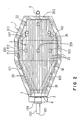
- Figs. 1 and 2 show embodiments for carrying out the charcoal production process and apparatus according to the present invention.
- the charcoal production apparatus in this embodiment according to the present invention is provided with a combustion furnace 1.
- the combustion furnace 1 has an in-kiln space 2 for placing therein a raw material 37 for the production of charcoal.
- This combustion furnace 1 is formed of, for example, concrete, and the interior of the combustion furnace 1 is lined with refractory bricks.
- the raw material 37 for charcoal may be wood such as thinnings and wood wastes and bamboo.
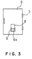
- the combustion furnace 1 includes a flame port 3 and a vent hole 4 each provided at the front end of the in-kiln space 2, and a smoke discharge opening 5 provided at the rear end of the in-kiln space 2.
- the flame port 3 and the vent hole 4 can be opened/closed by an opening/closing door 6 shown in Fig. 3.
- This opening/closing door 6 is mounted, for example; with a hinge 7 on the combustion furnace 1.
- This opening/closing door 6 may be constructed so as to be opened/dosed manually or in a remote control manner.
- An opening 6a communicatable with the vent hole 4 is provided at the lower part of the opening/closing door 6, and an opening/closing lid 8 for opening/closing this opening 6a is provided.
- This opening/closing lid 8 is mounted slidably in a vertical direction on a frame 9 fixed onto the opening/closing door 6.
- This opening/closing lid 8 is provided for allowing only the vent hole 4 to be opened/closed with the opening/closing door 6 closed.
- the smoke discharge opening 5 is in a chimney form protruded from the lower part of the rear end of the combustion furnace 1, and an opening/closing door 12 for opening/closing the smoke discharge port 5 is disposed at a connection to the combustion furnace 1.
- a raw material 37 for charcoal is placed in the center part of the in-kiln space 2, and firewoods 38, 39 are disposed at the upper part and the front part of the raw material 37 for charcoal.
- the raw material 37 for charcoal is fired with the firewoods 38, 39 and is then carbonized, and, in this case, air is introduced into the space 2 within the kiln through the vent hole 4.
- Smoke generated in the carbonization is discharged from the smoke discharge opening 5. This will be described later in more detail.
- the in-kiln space 2 comprises: a divergent part 20 in which the width gradually increases from the flame port 3 toward the center of the space 2 within the kiln; a maximum width part 21 which is connected to the divergent part 20 and is provided substantially at the center part of the space 2 within the kiln; and a convergent part 22 which extends from the maximum width part 21 and in which the width gradually decreases toward the smoke discharge opening 5.
- the floor 2a of the in-kiln space 2 is provided so as to incline downward from the flame port 3 toward the smoke discharge opening 5 (see Fig. 1).
- the inclination angle is preferably about 5 degrees.
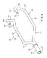
- the charcoal production apparatus is characterized by comprising air force feeding means for high temperature refining of the raw material 37 for charcoal.
- the air force feeding means includes a blast pipe 100 embedded within a concrete floor wall 1a from the front end to the rear end of the combustion furnace 1.
- This blast pipe 100 includes an air introduction port 101 protruded from the front end toward the exterior of the concrete floor wall 1a, and an air discharge opening 102 protruded from the rear end of the concrete floor wall 1a into the space 2 within the kiln.
- a leading pipe 103 having the air introduction port 101 is detachably connected through a coupling 104.
- the air introduction port 101 is connected to a blower (not shown) for forcibly feeding air into the blast pipe 100.
- blast pipe 100 includes first and second horizontal parts 105, 106 which extend in a two-way form from a portion near the air introduction port 101, and standing parts 107, 108 which respectively extend upward from rear parts of the first and second horizontal parts 105, 106, that is, from a part near the smoke discharge opening 5.
- the first and second horizontal parts 105, 106 are embedded within the concrete floor wall 1a, and the standing parts 107, 108 are exposed from the concrete floor wall 1a to the space 2 within the kiln.
- bending parts 109, 110 extending toward the front end of the in-kiln space 2 are provided respectively at the ends of the standing parts 107, 108.
- the air discharge opening 102 is provided at an open end of the bending parts 109, 110. Therefore, air is released from the air discharge opening 102 toward the fore of the in-kiln space 2.
- the air discharge opening 102 is preferably located at the upper part of in-kiln space 2 so that the released air is moved along the upper part of the in-kiln space 2 (see Fig. 1).
- the first and second horizontal parts 105, 106 may comprise a first part 111, which extends so as to correspond to the divergent part 20 of the in-kiln space 2, a second part 112, which extends so as to correspond to the maximum width part 21 in the in-kiln space 2, and a third part 113 which extends so as to correspond to the convergent part 22 in the in-kiln space 2.
- the blast pipe 100 when the blast pipe 100 is provided in the in-kiln space 2, the blast pipe 100 can be disposed so as to conform to the shape of the in-kiln space 2.
- the space in which the raw material for charcoal is placed can be made as large as possible.
- the standing parts 107, 108 are disposed so as to pass through a fire grate 32 which will be described later.
- the air forcibly fed into the air introduction port 101 from the blower (not shown) is branched in left and right horizontal parts 105, 106, is then released from left and right air discharge openings 102, is moved through over the raw material 37 for charcoal toward the front end of the in-kiln space 2, and sneaks from the front end to the lower side of the in-kiln space 2, so that it flows to the rear end.
- the temperature of the in-kiln space 2 is raised to activate the raw material 37 for charcoal, whereby high-temperature refining of the raw material 37 for charcoal is possible.
- predetermined gaps 40 as air passages are provided above the floor 2a of the combustion furnace 1, and a fire grate 32 is provided.
- This fire grate 32 extends from the flame port 3 in the combustion furnace 1 to a portion near the smoke discharge opening 5.
- the fire grate 32 is provided in a lattice form using a plurality of rod-like transverse members 34 and a plurality of rod-like longitudinal members 35 linked to the transverse members 34.
- the fire grate 32 is mounted on the floor 2a of the in-kiln space 2 through receiving members 36 (see Figs. 1 and 2).
- This fire grate 32 provides air passages on the floor 2a of the in-kiln space 2. Air fed through the vent hole 4 and air which is released from the air discharge opening 102 in the blast pipe 100 and sneaks from the front end of the in-kiln space 2 are passed through the air passages and are discharged from the rear end of the in-kiln space 2 into the smoke discharge opening 5. Fuel coal 33 such as scrap coal is evenly disposed on the upper surface of the fire grate 32. This fuel coal 33 releases radiation heat in carbonization refining of the raw material 37 for charcoal to contribute to homogenization of the in-kiln temperature. The raw material 37 for charcoal is arranged on the fuel coal 33 in a conventional embodiment, for example, in a standing state.
- thermometer 200 is a thermometer for high-temperature region measurement provided on the upper step in the center part
- thermometer 201 is a thermometer for medium-temperature region measurement provided on the middle step in the center part
- thermometer 202 is a thermometer for low-temperature region measurement provided on the lower step in the center part
- thermometer 203 is a thermometer for low-temperature region measurement provided near the smoke discharge opening 5.
- the controller regulates the feed rate of air or closes/opens the flame port 3, the vent hole 4, and the smoke discharge opening 5 based on the temperatures of the in-kiln space 2 measured with these thermometers, and the state of the step of carbonization attributable to this temperature.
- the raw material 37 for charcoal such as wood or bamboo is placed on the fire grate 32 through the fuel coal 33.
- firewood 38 is placed on the upper part of the raw material 37 for charcoal, and then firewood 39 is placed on the flame port 3.
- the firewood 39 placed on the flame port 3 is fired.
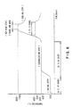
- Fire gradually moves into the firewood 38 located on the upper part of the raw material 37 for charcoal to initiate the step of drying the raw material 37 for charcoal. As shown in Fig. 6, this step of drying is continued at a temperature around 100°C (value measured with the thermometer 201) for about 24 to 48 hr.
- the step of drying is transferred to the step of carbonization to initiate thermal decomposition of the raw material 37 for charcoal.
- the flame port 3 is closed. In such a state that the vent hole 4 is opened, external air is allowed to flow into gaps 40 on the lower side of the fire grate 32.
- the step of carbonization is continued at an in-kiln temperature in the range of 300 to 400°C (value measured with the thermometer 201) for about 36 to 48 hr.
- the in-kiln temperature increases to 400 to 550°C (value measured with the thermometer 201) and bluish smoke is released from the smoke discharge opening 5, indicating that the step advances to the step of refining.
- air is forcibly fed from the blower (not shown) into the blast pipe 100. This force feeding air is released from the air discharge opening 102 in the blast pipe 100 into the rear end of the in-kiln space 2 and energetically flows along the upper part of the in-kiln space 2 toward the front end.
- the forcibly fed air sneaks from the front end of the in-kiln space 2 toward the downward side and, passes through gaps 40 on the lower side of the fire grate 32, again flows toward the rear end side, and is finally discharged through the smoke discharge opening 5.
- the temperature within the in-kiln space 2 is raised by forcibly feeding air into the in-kiln space 2 to increase the amount of oxygen. Further, radiation heat obtained from the burned coal 33 is also increased by creating the flow of air also on the lower side of the fire grate 40 to homogenize the in-kiln temperature, whereby high-temperature refining of the raw material 37 for charcoal can be realized.
- forcibly feeding air to keep the in-kiln temperature at 900 to 1100°C (value measured with the thermometer 201) followed by refining in this temperature range for 3 hr or more is desired. High-temperature refining at an in-kiln temperature of 800°C or above is possible.
- the force air blow rate is set by the in-kiln volume.
- the force air blow rate is preferably about 10 to 20 m 3 /min.
- the amount of water vapor in this case is preferably about 0.5 to 2.0 liters/min when the in-kiln value is 16 m 3 .
- the step of refining in the charcoal production process is generally carried out at an in-kiln temperature of about 400 to 550°C for 5 to 10 hr.
- the charcoal taken out of the combustion furnace 1 is high-temperature charcoal.
- the high-temperature charcoal has a high level of capability of adsorbing formaldehyde, benzene, toluene, xylene, ethyl benzene, chlorobenzene and the like. Therefore, when this high-temperature charcoal is mixed with low-temperature charcoal having a high level of capability of adsorbing ammonia, amine and the like, both the adsorption property of the high-temperature charcoal and the adsorption property of the low-temperature charcoal can be utilized and, consequently, a wide variety of harmful gases can be adsorbed.
- the gaps 40 which are provided as air passages below the fire grate 32 can be utilized.
- the provision of a large number of air release holes in the first and second horizontal parts 105, 106 allows air to be fed upward from the lower side of the in-kiln space 2.
- the charcoal production apparatus of the present invention is constructed so that the air forcibly fed into the in-kiln space is circulated vertically within the kiln. Therefore, the temperature difference between the upper part and the lower part within the in-kiln space is reduced, and refining treatment can always be carried out evenly at a high temperature to produce high-temperature charcoal with stable quality.
Landscapes
- Chemical & Material Sciences (AREA)
- Engineering & Computer Science (AREA)
- Oil, Petroleum & Natural Gas (AREA)
- Materials Engineering (AREA)
- Organic Chemistry (AREA)
- Coke Industry (AREA)
- Solid Fuels And Fuel-Associated Substances (AREA)
- Carbon And Carbon Compounds (AREA)
Applications Claiming Priority (3)
| Application Number | Priority Date | Filing Date | Title |
|---|---|---|---|
| JP2002193727 | 2002-07-02 | ||
| JP2002193727 | 2002-07-02 | ||
| PCT/JP2003/008416 WO2004013256A1 (ja) | 2002-07-02 | 2003-07-02 | 炭製造方法及び装置 |
Publications (1)
| Publication Number | Publication Date |
|---|---|
| EP1535982A1 true EP1535982A1 (de) | 2005-06-01 |
Family
ID=31492012
Family Applications (1)
| Application Number | Title | Priority Date | Filing Date |
|---|---|---|---|
| EP03741153A Withdrawn EP1535982A1 (de) | 2002-07-02 | 2003-07-02 | Verfahren und vorrichtung zur herstellung von holzkohle |
Country Status (7)
| Country | Link |
|---|---|
| US (1) | US20060099133A1 (de) |
| EP (1) | EP1535982A1 (de) |
| JP (1) | JPWO2004013256A1 (de) |
| CN (1) | CN1665906A (de) |
| AU (1) | AU2003281866A1 (de) |
| TW (1) | TW593660B (de) |
| WO (1) | WO2004013256A1 (de) |
Cited By (2)
| Publication number | Priority date | Publication date | Assignee | Title |
|---|---|---|---|---|
| DE102009060733A1 (de) | 2009-12-29 | 2011-06-30 | European Charcoal Ag | Vorrichtung zur kontinuierlichen Umwandlung von Biomasse und System zur Energiegewinnung daraus |
| US8859474B2 (en) | 2010-03-31 | 2014-10-14 | Chevron Oronite Company Llc | Lubricating oil compositions containing epoxide antiwear agents |
Families Citing this family (1)
| Publication number | Priority date | Publication date | Assignee | Title |
|---|---|---|---|---|
| FR2913236B1 (fr) * | 2007-03-01 | 2009-05-01 | Thermya Sa | Procede de fabrication de charbon vegetal a haute teneur en carbone et l'installation de mise en oeuvre du procede |
Family Cites Families (8)
| Publication number | Priority date | Publication date | Assignee | Title |
|---|---|---|---|---|
| US4510021A (en) * | 1979-07-25 | 1985-04-09 | Energy Products Of Idaho | Fluidized bed charcoal particle production system |
| CH646992A5 (de) * | 1980-02-26 | 1984-12-28 | Maurer A Ing Sa | Verfahren zur kontinuierlichen thermischen behandlung von verkohlbarem ausgangsmaterial. |
| SE465731B (sv) * | 1990-02-07 | 1991-10-21 | Kamyr Ab | Utvinning av energi och kemikalier ur massaavlutar under exponering av laagfrekvent ljud |
| JPH07242882A (ja) * | 1994-03-08 | 1995-09-19 | Shin Meiwa Ind Co Ltd | 炭化装置 |
| DE4408455A1 (de) * | 1994-03-12 | 1995-09-14 | Metallgesellschaft Ag | Verfahren zum Erzeugen von Holzkohle im Wanderbett |
| JPH0986910A (ja) * | 1995-09-28 | 1997-03-31 | Lignyte Co Ltd | 炭化物の製造方法 |
| JP2001107055A (ja) * | 1999-10-01 | 2001-04-17 | Kenji Yamane | 木炭製造方法及び木炭製造装置 |
| JP2002121016A (ja) * | 2000-10-10 | 2002-04-23 | Bio Carbon Kenkyusho:Kk | 連続式炭化炉と連続式炭化賦活炉 |
-
2003
- 2003-07-02 WO PCT/JP2003/008416 patent/WO2004013256A1/ja not_active Ceased
- 2003-07-02 AU AU2003281866A patent/AU2003281866A1/en not_active Abandoned
- 2003-07-02 CN CN038158124A patent/CN1665906A/zh active Pending
- 2003-07-02 JP JP2004525777A patent/JPWO2004013256A1/ja not_active Withdrawn
- 2003-07-02 TW TW092118105A patent/TW593660B/zh not_active IP Right Cessation
- 2003-07-02 US US10/518,204 patent/US20060099133A1/en not_active Abandoned
- 2003-07-02 EP EP03741153A patent/EP1535982A1/de not_active Withdrawn
Non-Patent Citations (1)
| Title |
|---|
| See references of WO2004013256A1 * |
Cited By (2)
| Publication number | Priority date | Publication date | Assignee | Title |
|---|---|---|---|---|
| DE102009060733A1 (de) | 2009-12-29 | 2011-06-30 | European Charcoal Ag | Vorrichtung zur kontinuierlichen Umwandlung von Biomasse und System zur Energiegewinnung daraus |
| US8859474B2 (en) | 2010-03-31 | 2014-10-14 | Chevron Oronite Company Llc | Lubricating oil compositions containing epoxide antiwear agents |
Also Published As
| Publication number | Publication date |
|---|---|
| JPWO2004013256A1 (ja) | 2006-09-21 |
| TW200402466A (en) | 2004-02-16 |
| TW593660B (en) | 2004-06-21 |
| US20060099133A1 (en) | 2006-05-11 |
| AU2003281866A1 (en) | 2004-02-23 |
| CN1665906A (zh) | 2005-09-07 |
| WO2004013256A1 (ja) | 2004-02-12 |
Similar Documents
| Publication | Publication Date | Title |
|---|---|---|
| CN102177221B (zh) | 炼焦炉中的用于初级空气的气体分配装置 | |
| JP2009002594A (ja) | 小型籾殻灰製造燃焼炉 | |
| EP1535982A1 (de) | Verfahren und vorrichtung zur herstellung von holzkohle | |
| JP6285588B1 (ja) | 自燃炭化熱処理装置及びこれを使用した自燃炭化熱処理方法 | |
| RU2186299C2 (ru) | Печь-калорифер | |
| JP2011174703A (ja) | 脱脂炉 | |
| JP2004339327A (ja) | 炭化装置 | |
| JP7231528B2 (ja) | バッチ式炭化装置 | |
| JP2010248362A (ja) | 炭化炉 | |
| JPH0616890Y2 (ja) | 焼結炉 | |
| JPS63315576A (ja) | 脱脂炉 | |
| US4531910A (en) | Down draft kiln | |
| JP2001107055A (ja) | 木炭製造方法及び木炭製造装置 | |
| JPH08157832A (ja) | 竹材等の処理方法 | |
| KR200294583Y1 (ko) | 벽난로용 다중 연소장치 | |
| KR101377252B1 (ko) | 폐 수지 및 카본으로부터 귀금속 회수장치 | |
| JP3153809U (ja) | 火葬炉 | |
| JP3477572B2 (ja) | 炭化炉を兼ねたストーブ及びボイラー | |
| KR20050016661A (ko) | 숯 제조방법 및 제조장치 | |
| JP2010070661A (ja) | 炭化装置 | |
| JP7190726B2 (ja) | 自燃炭化熱処理装置及び炭化熱処理システム、並びにこれを使用した炭化物の製造方法 | |
| JP2005023131A (ja) | 炭化装置 | |
| US9808859B2 (en) | Furnace assembly | |
| JP2010241973A (ja) | 炭化炉 | |
| JP2000186817A (ja) | ストーブ |
Legal Events
| Date | Code | Title | Description |
|---|---|---|---|
| PUAI | Public reference made under article 153(3) epc to a published international application that has entered the european phase |
Free format text: ORIGINAL CODE: 0009012 |
|
| 17P | Request for examination filed |
Effective date: 20050108 |
|
| AK | Designated contracting states |
Kind code of ref document: A1 Designated state(s): AT BE BG CH CY CZ DE DK EE ES FI FR GB GR HU IE IT LI LU MC NL PT RO SE SI SK TR |
|
| AX | Request for extension of the european patent |
Extension state: AL LT LV MK |
|
| DAX | Request for extension of the european patent (deleted) | ||
| STAA | Information on the status of an ep patent application or granted ep patent |
Free format text: STATUS: THE APPLICATION HAS BEEN WITHDRAWN |
|
| 18W | Application withdrawn |
Effective date: 20070201 |