EP1535787B1 - Tankdeckel - Google Patents
Tankdeckel Download PDFInfo
- Publication number
- EP1535787B1 EP1535787B1 EP04027489A EP04027489A EP1535787B1 EP 1535787 B1 EP1535787 B1 EP 1535787B1 EP 04027489 A EP04027489 A EP 04027489A EP 04027489 A EP04027489 A EP 04027489A EP 1535787 B1 EP1535787 B1 EP 1535787B1
- Authority
- EP
- European Patent Office
- Prior art keywords
- torque
- closer
- engagement element
- click
- handle mechanism
- Prior art date
- Legal status (The legal status is an assumption and is not a legal conclusion. Google has not performed a legal analysis and makes no representation as to the accuracy of the status listed.)
- Expired - Lifetime
Links
Images


Classifications
-
- B—PERFORMING OPERATIONS; TRANSPORTING
- B60—VEHICLES IN GENERAL
- B60K—ARRANGEMENT OR MOUNTING OF PROPULSION UNITS OR OF TRANSMISSIONS IN VEHICLES; ARRANGEMENT OR MOUNTING OF PLURAL DIVERSE PRIME-MOVERS IN VEHICLES; AUXILIARY DRIVES FOR VEHICLES; INSTRUMENTATION OR DASHBOARDS FOR VEHICLES; ARRANGEMENTS IN CONNECTION WITH COOLING, AIR INTAKE, GAS EXHAUST OR FUEL SUPPLY OF PROPULSION UNITS IN VEHICLES
- B60K15/00—Arrangement in connection with fuel supply of combustion engines or other fuel consuming energy converters, e.g. fuel cells; Mounting or construction of fuel tanks
- B60K15/03—Fuel tanks
- B60K15/04—Tank inlets
- B60K15/0406—Filler caps for fuel tanks
-
- Y—GENERAL TAGGING OF NEW TECHNOLOGICAL DEVELOPMENTS; GENERAL TAGGING OF CROSS-SECTIONAL TECHNOLOGIES SPANNING OVER SEVERAL SECTIONS OF THE IPC; TECHNICAL SUBJECTS COVERED BY FORMER USPC CROSS-REFERENCE ART COLLECTIONS [XRACs] AND DIGESTS
- Y10—TECHNICAL SUBJECTS COVERED BY FORMER USPC
- Y10S—TECHNICAL SUBJECTS COVERED BY FORMER USPC CROSS-REFERENCE ART COLLECTIONS [XRACs] AND DIGESTS
- Y10S220/00—Receptacles
- Y10S220/33—Gasoline tank cap
Definitions
- the present invention relates to a cap device having a torque mechanism for sealing a tank opening with a rotational torque of a predetermined level.
- the fuel cap includes a closer to seal a tank opening, a cover with a handle for rotational operations, and a torque mechanism.
- the torque mechanism includes a coil spring that is located between the cover and the closer, and a click mechanism that includes mating engagement elements respectively formed on the cover and the closer. Coupling of the engagement elements is released to give a click sound, in response to a relative rotation of the cover to the closer by a preset angle.
- the object of the invention is to provide a cap device including a torque mechanism that has a simple structure and consists of a less number of parts to give a click.
- the present invention is directed to a cap device that closes a tank opening and engages with an opening engagement element formed around periphery of the tank opening.
- the cap device includes: a closer that seals the tank opening and has a cap engagement element, which is engaged with the opening engagement element by rotation of the closer by a preset angle; a handle mechanism that is attached to an upper portion of the closer in a rotatable manner to selectively rotate the closer in a closing direction and an opening direction to close and open the tank opening; and a torque mechanism that is provided between the handle mechanism and the closer and selectively transmits a rotational torque in the closing direction and the opening direction to the closer.
- the torque mechanism includes: a click unit having a first click engagement element and a second click engagement element that mates with the first click engagement element, where the first click engagement element and the second click engagement element are disengaged and shift from an initial position to a released position to give a click sound, when the handle mechanism and the closer are rotated relative to each other by the preset angle in response to an operation of the handle mechanism in the closing direction; and a torque transmission unit having a first torque engagement element and a second torque engagement element that mates with the first torque engagement element, the torque transmission unit transmitting a rotational torque in the closing direction applied to the handle mechanism to the closer via coupling of the first torque engagement element with the second torque engagement element.
- At least one of the first torque engagement element and the second torque engagement element is a cantilever spring that is elastically deformed by the rotation of the handle mechanism in the closing direction to transmit the rotational torque to the closer while accumulating a spring force.
- the cantilever spring applies the accumulated spring force to restore the click unit from the released position to the initial position when the rotational torque applied to the handle mechanism is released.
- the cap engagement element formed on the closer engages with the opening engagement element formed on the tank opening to rotate the closer via the torque mechanism.
- the rotational torque is transmitted from the first torque engagement element to the second torque engagement element in the torque mechanism.
- At least one of the first torque engagement element and the second torque engagement element is the cantilever spring that is elastically deformed by the rotation of the handle mechanism in the closing direction to transmit the rotational torque to the closer while accumulating the spring force.
- the click unit gives a click sound in response to a relative rotation of the handle mechanism to the closer by a preset angle.
- At least one of the first torque engagement element and the second torque engagement element is structured as the cantilever spring.
- the cap device of the invention does not require any coil spring used in the prior art structure, thus desirably decreasing the total number of parts and simplifying the structure.
- the torque mechanism includes a torque plate that is located between the handle mechanism and the closer in a freely rotatable manner.
- the first torque engagement element is a torque transmission rib formed on the handle mechanism
- the second torque engagement element is a cantilever spring that is protruded from the torque plate in an elastically deformable manner to engage with the torque transmission rib and increase the spring force with an increase in degree of elastic deformation.
- the cantilever spring is engaged with the torque transmission rib by rotation of the handle mechanism to be deformed and transmit the rotational torque.
- the cantilever spring may be protruded upright in a substantially vertical direction from the torque plate.
- the handle mechanism includes a cover and a handle that is protruded from a top face of the cover and has a recess
- the cantilever spring is received in the recess. This structure enables the cantilever spring to have a sufficient length in the vertical direction and thereby ensures a high level of elastic deformation.
- the torque mechanism includes a torque plate that is located between the handle mechanism and the closer in a freely rotatable manner.
- the first click engagement element is a click arm that is formed as a cantilever on the torque plate and has a click engagement projection.
- the second click engagement element is a click engagement element formed on the handle mechanism.
- the torque mechanism has a stopper mechanism that stops rotation of the closer to prevent a torque applied to the closer from exceeding a torque limit of closing the tank opening.
- the stopper mechanism effectively prevents the closer from being clamped excessively.
- the stopper mechanism may have a projection that is protruded from the closer to engage with the opening engagement element and thereby stop rotation of the closer.
- the cantilever spring has a spring constant that increases with an increase in rotational torque applied to the handle mechanism after the stop mechanism works to stop rotation of the closer.
- the rotational torque in response to a ration of the handle mechanism after the function of the stopper mechanism to stop rotation of the closer, the rotational torque does not rise abruptly but increases stepwise. This arrangement effectively prevents the user from incorrectly recognizing completion of a closing operation of the cap device. The user can thus naturally continue the closing operation to hear a click.
- One preferable structure of varying the spring constant of the cantilever spring has a restriction member to partially restrict a motion of the cantilever spring, and the restriction member partially restricts the motion of the cantilever spring to vary the spring constant stepwise.
- the restriction member may include a first step that is formed at a position of pressing the cantilever spring, and a second step that is formed to press the cantilever spring at a position of a greater rotational angle of the handle mechanism than the position of the first step.
- the cantilever spring is formed in spiral and is expanded or contracted by transmission of the rotational torque from the handle mechanism to generate the spring force.
- Fig. 1 is a half sectional view showing a fuel cap in a first embodiment of the invention
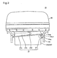
- Fig. 2 shows the fuel cap that is screwed to a filler neck to close an inlet opening
- Fig. 3 is a perspective view showing the fuel cap detached from the filler neck
- Fig. 4 is an enlarged sectional view showing a gasket attached to a seal support element of the fuel cap
- Fig. 5(A), 5(B) and 5(C) show a process of compressing the gasket as the fuel cap is closed;
- Fig. 6 is a graph showing variations in reactive force against the flexure length of the gasket
- Fig. 7 is a graph showing variations in sealing face pressure against the flexure length of the gasket
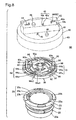
- Fig. 8 is a decomposed perspective view showing a torque mechanism located on a cover and an upper portion of a cap main body;
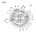
- Fig. 9 is a top view of the torque mechanism
- Fig. 10(A) and 10(B) show operations of a first transmission mechanism of a torque transmission unit
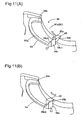
- Fig. 11(A) and 11(B) show operations of a click unit
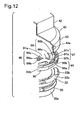
- Fig. 12 is a perspective view showing part of the torque mechanism shown in Fig. 8;
- Fig. 13 is a sectional view showing the side of the fuel cap
- Fig. 14 shows periphery of a torque plate included in the torque mechanism
- Fig. 15 shows functions of first spring elements and second spring elements
- Fig. 16 shows a series of operations of the torque mechanism
- Fig. 17 shows the series of operations of the torque mechanism after the state of Fig. 16;
- Fig. 18 shows the series of operations of the torque mechanism after the state of Fig. 17;
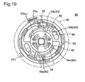
- Fig. 19 shows the series of operations of the torque mechanism after the state of Fig. 18;
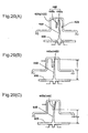
- Fig. 20(A), 20(B) and 20(C) show essential part of a torque transmission unit in a second embodiment of the invention
- Fig. 21 is a graph showing a variation in rotational torque against rotational angle of a handle
- Fig. 22 shows essential part of a torque transmission unit in a third embodiment of the invention.
- Fig. 23(A), 23(B) and 23(C) show operations of the torque transmission unit in the third embodiment
- Fig. 24 shows essential part of a torque transmission unit in a fourth embodiment of the invention.
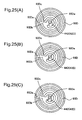
- Fig. 25(A), 25(B) and 25(C) show operations of the torque transmission unit in the fourth embodiment
- Fig. 26 shows essential part of a torque transmission unit in a fifth embodiment of the invention.
- Fig. 27(A), 27(B), 27(C) and 27(D) show operations of the torque transmission unit in the fifth embodiment.
- Fig. 1 is a half sectional view showing a fuel cap 10 (cap device) in a first embodiment of the invention.
- the fuel cap 10 is attached to a filler neck FN having an inlet opening FNb (tank opening) to feed a supply of fuel to a fuel tank (not shown).
- FNb tank opening
- the fuel cap 10 has a cap main body 20 (closer) that is made of a synthetic resin material like polyacetal, a cover 40 that is mounted on the cap main body 20 and is made of a synthetic resin material like nylon with a handle, an inner cover 30 that closes an upper opening of the cap main body 20 and forms a valve chest 25, a pressure regulating valve 50 that is received in the valve chest 25, a torque mechanism 80, and a ring-shaped gasket GS that is attached to the upper outer circumference of the cap main body 20 to seal the cap main body 20 against the filler neck FN.
- a cap main body 20 closer
- a cover 40 that is mounted on the cap main body 20 and is made of a synthetic resin material like nylon with a handle
- an inner cover 30 that closes an upper opening of the cap main body 20 and forms a valve chest 25, a pressure regulating valve 50 that is received in the valve chest 25, a torque mechanism 80, and a ring-shaped gasket GS that is attached to the upper outer circumference of the cap main body
- the cap main body 20 has a substantially cylindrical outer tube 20a with a male threading element 21, which engages with a female threading element FNc formed on the inner wall of the pipe-shaped filler neck FN (opening-formation member), and a valve chest-formation member 20b that is located in the lower portion of the inside of the outer tube 20a.
- the valve chest-formation member 20b receives a positive pressure valve and a negative pressure valve functioning as the pressure regulating valve 50 therein.
- the inner cover 30 is pressed into the upper portion of the valve chest-formation member 20b to cover over the valve chest 25.
- the gasket GS is set on a lower face of an upper flange 22 of the cap main body 20.
- the gasket GS is located between a seal support element 24 of the flange 22 and the inlet opening FNb of the filler neck FN.
- the gasket GS is pressed against the seal support element 24 to exert the sealing effects.
- Fig. 2 shows the fuel cap 10 that is screwed to the filler neck FN to close the inlet opening FNb.
- Fig. 3 is a perspective view showing the fuel cap 10 detached from the filler neck FN.
- a screw mechanism is formed on the inner circumferential wall of the filler neck FN and the outer circumference of the outer tube 20a of the cap main body 20.
- the screw mechanism functions to screw the fuel cap 10 to the filler neck FN, and includes the female threading element FNc formed on the inner wall of the filler neck FN and the male threading element 21 formed on the lower portion of the outer circumference of the outer tube 20a.
- the female threading element FNc is threading projections from a leader FNc1 close to the inlet opening FNb toward the depth of the fuel tank.
- the male threading element 21 has a thread ridge 21a and a thread groove 21b.
- the lower end of the thread ridge 21a is a leader 21c that engages with the leader FNc1 of the female threading element FNc (see Fig. 2).
- a stopper 21d is formed upright to cross the thread groove 21b. The stopper 21d is located at a position of about 200 degrees from the leader 21c of the male threading element 21.
- the female threading element FNc has a screw thread pitch of 6.35 mm per rotation.
- Fig. 4 is an enlarged sectional view showing the gasket GS set in the seal support 24 of the fuel cap 10.
- the gasket GS is made of fluorocarbon rubber and has a gasket main body GSa that is formed to have a substantially C-shaped cross section and is compressed to shorten the length in its bending direction.
- the gasket main body GSa of the C-shaped cross section is formed to surround a slit GSb of a substantially U-shaped cross section, which is open to the outer side.
- the gasket main body GSa includes a first lip GSc that is pressed against the sealing face FNf of the filler neck FN, a second lip GSd, and a link GSe that links the first lip GSc to the second lip GSd.
- the first lip GSc, the second lip GSd, and the link GSe form the C-shaped cross section of the gasket main body GSa.
- the first lip GSc is longer than the second lip GSd to bring the edge of the first lip GSc into contact with a first sealing wall 24a when the gasket GS is compressed by the sealing face FNf (see Fig. 5(C)).
- a baffle element GSf is protruded from the inner side of the gasket main body GSa to be located between the second lip GSd and the link GSe.
- the seal support 24 is a circular recess to support the outer circumference of the gasket GS.
- the seal support 24 has a first sealing wall 24a that supports the second lip GSd, a stopper step 24b functioning as a stopper element, a second sealing wall 24c, and a lower sealing face 24d.
- the stopper step 24b positions the baffle element GSf of the gasket GS and thereby functions to stop rotation of the gasket GS when the first lip GSc is compressed by the sealing face FNf.
- the second sealing wall 24c faces the link GSe of the gasket GS across a gap Gp.
- the gasket GS is elastically deformed to narrow the gap Gp when the first lip GSc receives a compressive force from the sealing face FNf.
- the second sealing wall 24c has a circular sealing recess 24e to receive a gate end GSh, which is protruded from the outer circumference of the link GSe of the gasket GS.
- the gate end GSh is a trace of the gate used for injection molding the gasket GS.
- the sealing recess 24e functions to equalize the sealing face pressure in the circumferential direction when the gate end GSh comes into contact with the second sealing wall 24c.
- Fig. 5 shows a process of compressing the gasket GS as the fuel cap 10 is closed.
- the first lip GSc of the gasket GS comes into contact with the sealing face FNf (Fig. 5(A)).
- the further closing operation causes the first lip GSc to be compressed in the bending direction and narrow the opening of the slit GSb (Fig. 5(B)).
- the baffle element GSf of the gasket GS is positioned by the stopper step 24b to prohibit rotation of the gasket GS.
- the link GSe is deformed to narrow the gap Gp relative to the second sealing wall 24c.
- the edge of the first lip GSc comes into contact with the first sealing wall 24a on the immediate side of the edge of the second lip GSd. This completes compression of the gasket (Fig. 5(C)), so that the fuel cap 10 closes the inlet opening FNb.
- Fig. 6 is a graph showing variations in reactive force against the flexure length of the gasket.
- the solid-line curve regards the gasket GS of the embodiment and the dotted-line curve regards a prior art C-shaped gasket.
- the flexure length represents a compressed length (compression degree) of the gasket in its bending direction.
- the relation between the flexure length and the rotational angle of the fuel cap depends upon various parameters like the hardness and the shape of the gasket. In an example where a 360-degree rotation of a fuel cap gives a flexure length of 6.35 mm, the fuel cap closed at an angle of 198 degrees gives a flexure length of 3.5 mm. The fuel cap rotated from its full close position in its opening direction by 90 degrees gives a flexure length of 1.9 mm.
- the closing operation of the fuel cap bends the gasket and increases the reactive force of the gasket.
- the reactive force of greater than 150 N produced in the closing operation of the fuel cap deteriorates the operating performance of the fuel cap.
- the reactive force is thus preferably not greater than 150 N or more preferably not greater than 130 N.
- the prior art gasket gives only a flexure length of about 1.5 mm at the reactive force of 150 N and has an abrupt increase in reactive force to deteriorate the operating performance.
- the gasket GS of the embodiment gives a flexure length of at least 4.5 mm in the full close position and does not have any abrupt increase in reactive force to ensure the good operating performance.
- Fig. 7 is a graph showing variations in sealing face pressure against the flexure length of the gasket.
- the solid-line curve regards the gasket GS of the embodiment and the dotted-line curve regards the prior art C-shaped gasket.
- the sealing face pressure represents a pressure of the gasket against the sealing face FNf.
- the stopper 21d defines the full closing depth to be not less than 2 mm or preferably to be in a range of 3 to 5 mm.
- the combination of the stopper 21d and the stopper step 24b positions the gasket GS and stops rotation of the gasket GS.
- the link GSe is readily deformed to narrow the gap Gp relative to the second sealing wall 24c. This arrangement gives a sufficiently large sealing face pressure with a relatively small closing force and ensures the good operating performance.
- the first lip GSc is designed to be longer than the second lip GSd.
- the sealing face FNf is pressed against the first lip GSc to compress the gasket GS, the end of the long first lip GSc comes into contact with the first sealing wall 24a. This design prevents the first lip GSc from coming into contact with the second lip GSd to interfere with sufficient deformation, thus attaining a sufficiently high displacement with a relatively little loading.
- the fuel cap 10 may adopt a quick-turn structure to open and close the inlet opening FNb by simple rotation of a preset angle, for example, 180 degrees.
- the cover 40 is generally required to have a lost motion mechanism that idles in the range of a preset angle, in order to prevent a decrease in sealing face pressure of the gasket due to an external force applied to the cover 40.
- the gasket GS of the embodiment ensures the high sealing properties even when the cover 40 receives an external force and rotates in its opening direction by approximately 90 degrees in to decrease the flexure length to about 1.6 mm.
- the gasket GS of the embodiment thus ensures the sufficient sealing face pressure of or over a preset level without the lost motion mechanism of the complicated structure.
- the fuel cap 10 of the embodiment has the large screw thread pitch to move the cap main body 20 by at least 3 mm in the axial direction with a rotation of 180 degrees. This structure enables the fuel cap 10 to be opened and closed by rotation of a small angle and thus ensures the good operating performance.
- the gasket GS preferably has the reactive force of not higher than 100 N against the flexure length of 4 mm and the sealing face pressure of not lower than 0.5 MPa. It is preferable that a rotation of the closer by 80 to 90 degrees from the closing start position is equivalent to a moving distance of 1.4 mm to 1.6 mm in the axial direction. This arrangement desirably ensures the sufficient sealing properties of the gasket GS even when the closer is rotated by approximately 90 degrees in its opening direction from the full close position due to an external force.
- the cover 40 functions as a manipulating mechanism and is attached to the flange 22 via the torque mechanism 80 in a rotatable and freely detachable manner.
- the cover 40 includes an upper wall 41, a handle 42 mounted on the upper wall 41, and a side wall 43 formed around the upper wall 41, and is integrally made of a conductive resin by injection molding.
- Four engagement projections 43a are protruded inward from the side wall 43 to be arranged at equal intervals along the circumference.
- the engagement projections 43a function to fix the cover 40 to the cap main body 20 via the torque mechanism 80.
- the attachment structure of the cover 40 will be discussed later.
- Fig. 8 is a decomposed perspective view illustrating the torque mechanism 80 located on the cover 40 and the upper portion of the cap main body 20.
- Fig. 9 is a top view of the torque mechanism 80.
- the torque mechanism 80 includes a torque transmission unit 82 and a click unit 84 as shown in Fig. 9.
- the click unit 84 clicks when the rotational torque transmitted by the torque transmission unit 82 exceeds a preset level of rotational torque in a closing operation of the fuel cap 10 to close the inlet opening FNb as shown in Fig. 3.
- the click sound enables the user to confirm that the fuel cap 10 is fastened to the filler neck FN with a rotational torque of or over the preset level.
- the torque mechanism 80 includes a torque plate 90 that is located in a rotatable manner between the cover 40 and the cap main body 20.
- the torque plate 90 has a disc-shaped torque body 91 made of a resin.
- the torque body 91 includes a disc-shaped arm support 91a, an outer ring 91b surrounding the arm support 91a, and a link 91c linking the arm support 91a to the outer ring 91b.
- Guide grooves, torque arms, cantilever springs, and spring elements are formed on the torque body 91. These elements function as the torque transmission unit 82 and the click unit 84.
- the torque transmission unit 82 has a pair of first transmission mechanisms to transmit the rotational torque from the cover 40 to the torque plate 90 and a pair of second transmission mechanisms to transmit the rotational torque from the torque plate 90 to the cap main body 20.
- Each of the first transmission mechanisms includes a torque transmission rib 44 formed on the cover 40 and a cantilever spring 93 that is protruded from the torque plate 90 in an elastically deformable manner.
- the torque transmission rib 44 is formed on an inner wall 42a of the handle 42 to be extended in a radial direction.
- the two torque transmission ribs 44 are arranged about a center axis of the cover 40 to be apart from each other by a predetermined distance.
- the cantilever spring 93 is a columnar member integrally formed with the torque body 91 to be protruded from the plane of the torque body 91 in the vertical direction.
- the cantilever spring 93 is inserted into a recess 42b of the handle 42, and has an engagement end 93a that engages with the torque transmission rib 44.
- Fig. 10 shows operations of the first transmission mechanism of the torque transmission unit 82.
- the torque transmission rib 44 engages with the engagement end 93a of the cantilever spring 93 and transmits the rotational torque to the torque plate 90 as shown in Fig. 10(A).
- the cantilever spring 93 is deformed and inclined to accumulate the spring force in an opening direction with an increase in degree of elastic deformation. The functions of the spring force will be discussed later.
- the first transmission mechanism further includes a guide projection 46 protruded from the inner face of the upper wall 41 of the cover 40 and a rib guide element 95 formed in the torque plate 90.
- the guide projection 46 is a cylindrical projection to mainly transmit the rotational torque in an opening direction.
- the rib guide element 95 is an arc-shaped groove formed in the torque plate 90 and has two ends functioning as pressure ends 95a and 95b. The rib guide element 95 movably supports the guide projection 46 inserted and received therein.
- Each of the second transmission mechanisms includes a guide projection 92 formed on the bottom face of the torque plate 90 and a body engagement element 23 formed on the cap main body 20 to transmit the rotational torque from the torque plate 90 to the cap main body 20.
- the body engagement element 23 is located on the inner circumference of the flange 22, and includes a pair of pressure projections 23a and 23b that are arranged across a predetermined interval and a guide step 23c that is formed between the pair of pressure projections 23a and 23b.
- the guide projection 92 that is received in the guide step 23c comes into contact with one pressure projection 23a in response to rotation of the torque plate 90 in a closing direction, while coming into contact with the other pressure projection 23b in response to rotation of the torque plate 90 in an opening direction. This structure accordingly transmits the rotational torque from the torque plate 90 to the cap main body 20.
- the click unit 84 includes a pair of click engagement elements 45 protruded from the bottom of the upper wall 41 of the cover 40 and a pair of click arms 94 formed on the torque plate 90.
- Each of the click engagement elements 45 includes a pressure plane 45a formed to face in the radially outward direction and a downward inclined plane 45b formed to face in the circumferential direction.
- Each of the click arms 94 includes an arm body 94a protruded from the arm support 91a and a click engagement projection 94c protruded upward from a free end of the arm body 94a.
- the click arm 94 is a cantilever with a support base 94b as the fulcrum.
- the click engagement projection 94c is located apart from the torque body 91 by a predetermined distance.
- a vertical wall 94c1 is formed on one end of the click engagement projection 94c to face in the radially inward direction and is pressed by the pressure plane 45a of the click engagement element 45.
- An inclined plane 94c2 is formed to face in the circumferential direction and is pressed by the inclined plane 45b of the click engagement element 45.
- Fig. 11 shows operations of the click unit 84.
- the pressure plane 45a of the click engagement element 45 presses the vertical wall 94cl of the click engagement projection 94c.
- the click arm 94 is accordingly deformed outward with the support base 94b as the fulcrum and is caught by the click engagement element 45.
- the pressure plane 45a of the click engagement element 45 rides over the vertical wall 94c1 of the click engagement projection 94c.
- the click engagement projection 94c accordingly bumps against the outer circumference of the arm support 91a to give a click sound.
- Fig. 11 shows operations of the click unit 84.
- the inclined plane 45b of the click engagement element 45 presses the inclined plane 94c2 of the click arm 94 to press the click arm 94 down with the support base 94b as the fulcrum.
- the click arm 94 requires a smaller level of rigidity for a downward deformation, compared with the rigidity required for an outward deformation.
- the click engagement element 45 and the click engagement projection 94c smoothly slip against each other via the respective inclined planes 45b and 94c2. The rotation in the opening direction accordingly gives a smaller click sound than the rotation in the closing direction.
- Fig. 12 is a perspective view showing essential part of the torque mechanism 80 shown in Fig. 8.
- Fig. 13 is a sectional view showing the side of the fuel cap 10.
- Catching claws 98a of plate engagement elements 98 are formed along the inner circumference of the outer ring 91b of the torque plate 90.
- the catching claws 98a are protruded from the inner wall of the outer ring 91b toward the center axis and are formed to be observable from the top through notches 98b and elastically deformable in the axial direction.
- Arc-shaped catching projections 22b are formed on the outer circumference of the flange 22 of the cap main body 20.
- the torque plate 90 is attached to the cap main body 20 in a rotatable manner through engagement of the catching claws 98a with the catching projections 22b.
- Fixation elements 99 are arranged on the outer circumference of the outer ring 91b of the torque plate 90. Each of the fixation elements 99 has a catching recess 99b to form a catching claw 99a.
- the engagement projections 43a formed inward on the side wall 43 of the cover 40 are fit in the catching recesses 99b of the mating fixation elements 99, so that the torque plate 90 supports the cover 40 in a rotatable manner (approximately 20 degrees).
- the fixation positions of the engagement projections 43a with the catching recesses 99b of the fixation elements 99 is located above the fixation positions of the catching claws 98a of the plate engagement elements 98 with the catching projections 22b of the flange 22.
- the torque plate 90 is attached to the cap main body 20 through engagement of catching claws 98a of the plate engagement elements 98 of the torque plate 90 with the catching projections 22b of the flange 22 of the cap main body 20.
- the cover 40 is then attached to the torque plate 90 through engagement of the engagement projections 43a of the cover 40 with the catching claws 99a of the torque plate 90. This assembles the cap main body 20, the torque plate 90, and the cover 40 to the fuel cap 10.
- Fig. 14 shows the periphery of the torque plate 90.
- the torque plate 90 has first spring elements 96 and second spring elements 97 to hold the torque plate 90 between the bottom face of the upper wall 41 of the cover 40 and the upper portion of the cap main body 20.
- the four first spring elements 96 are arranged at angles of 90 degrees in the circumferential direction on the center portion of the torque plate 90.
- the first spring elements 96 apply a spring force in a vertical direction to the bottom face of the upper wall 41 of the cover 40.
- Fig. 10 shows the torque plate 90.
- the torque plate 90 has first spring elements 96 and second spring elements 97 to hold the torque plate 90 between the bottom face of the upper wall 41 of the cover 40 and the upper portion of the cap main body 20.
- the four first spring elements 96 are arranged at angles of 90 degrees in the circumferential direction on the center portion of the torque plate 90.
- the first spring elements 96 apply a spring force in a vertical direction to the bottom face of the upper wall 41 of the cover 40.
- each of the first spring elements 96 has an arm 96a that is formed on the same plane as the top face of the torque plate 90 and is extended as a cantilever in the circumferential direction, and a pressure projection 96b that is formed on a free end of the arm 96a to be protruded upward from the top face of the torque plate 90.
- Each of the second spring elements 97 has an arm body 97a that is formed as a cantilever slightly inclined downward, and a pressure projection 97b that is formed on a free end of the arm body 97a to be pressed against an inclined upper plane 22a of the flange 22.
- One end of the second spring element 97 is tilted in a notch 97c formed on the top face of the torque plate 90.
- the pressure projections 97b of the second spring elements 97 press the inclined upper plane 22a of the flange 22, so that the second spring elements 97 are positioned in both the vertical direction and in the radial direction.
- the torque mechanism 80 has the two torque transmission ribs 44, 44, the two guide projections 46, 46, and the two cantilever springs 93, 93 arranged symmetrically about the rotational axis of the cover 40.
- the following description thus mainly regards only one set of the symmetrical structure of the torque mechanism 80.
- the user holds the handle 42 of the cover 40 and inserts the cap main body 20 in the axial direction into the open inlet opening FNb.
- the leader 21c of the male threading element 21 is set on the leader FNc1 of the female threading element FNc.
- the torque mechanism 80 performs a series of operations as shown in Figs. 16 to 19.
- the torque transmission rib 44 engages with the engagement end 93a of the cantilever spring 93 to incline the cantilever spring 93, while the click engagement element 45 engages with the click engagement projection 94c of the click arm 94.
- the clockwise rotational force applied to the handle 42 is accordingly transmitted to the torque plate 90 to rotate the torque plate 90 clockwise.
- the guide projection 92 presses the pressure projection 23a of the body engagement element 23.
- the cover 40, the torque plate 90, and the cap main body 20 then rotate integrally in the closing direction of the inlet opening FNb.
- the rotational torque transmitted from the handle 42 to the cap main body 20 increases with an increase in inclined angle of the cantilever spring 93 by the torque transmission rib 44 as shown in Fig. 10.
- the click engagement element 45 rides over the click arm 94 as shown in Fig. 17 to be set in a released position shown in Fig. 18.
- the click engagement projection 94c comes over the click engagement element 45 and bumps against the outer circumference of the arm support 91a to give a click sound.
- the user can thus confirm that the fuel cap 10 is successfully clamped.
- the guide projection 46 is guided and moves in the rib guide element 95 to come into contact with the pressure end 95a. Even when the user tries to continue rotating the handle 42 in the closing direction in this state, the stopper 21d is in contact with the leader FNc1 of the filler neck FN.
- This structure desirably prevents the cap main body 20 from being clamped excessively.
- the cantilever spring 93 applies a counterclockwise rotational force to the cover 40 via the torque transmission rib 44 as shown in Fig. 19.
- the inclined plane 45b of the click engagement element 45 presses the click arm 94 down to be slid against and ride over the click engagement projection 94c as shown in Fig. 11.
- the guide projection 46 moves in the rib guide element 95 to come into contact with the pressure end 95b and stop rotation of the cover 40.
- the fuel cap 10 closes the inlet opening FNb in this state.
- the user In order to open the fuel cap 10, the user holds the handle 42 of the cover 40 and applies a counterclockwise rotational force to the cover 40 in the state of Fig. 19.
- the guide projection 46 of the cover 40 then presses the pressure end 95b of the rib guide element 95 formed in the torque plate 90 to rotate the torque plate 90.
- the guide projection 92 presses the pressure projection 23b of the body engagement element 23.
- the rotational force applied to the cover 40 is then transmitted to the cap main body 20 via the guide projection 46, the torque plate 90, and the pressure projection 23b of the body engagement element 23.
- the cover 40, the torque plate 90, and the cap main body 20 thus integrally rotate counterclockwise.
- Rotation of the cap main body 20 integrally with the cover 40 by approximately 180 degrees causes the male threading element 21 to be released from the leader FNc1 of the female threading element FNc of the filler neck FN.
- the cap main body 20 is accordingly released from the binding force of the filler neck FN.
- the fuel cap 10 is then detached from the filler neck FN to open the inlet opening FNb.
- the structure of the first embodiment achieves the following effects, in addition to those discussed above. 1.
- a click sound is given when the click engagement elements 45 of the cover 40 ride over the mating click engagement projections 94c. The user can thus confirm that the fuel cap 10 is clamped with a fixed torque, regardless of the elasticity of the gasket GS.
- the cantilever springs 93 included in the torque transmission unit 82 are formed integrally with the torque plate 90. This simplified structure does not require any coil spring used in the prior art structure and desirably reduces the required number of parts.
- the cantilever springs 93 are protruded upright in the substantially vertical direction from the torque plate90 and are received in the recess 42b of the handle 42. This structure enables the cantilever springs 93 to have a sufficient length in the vertical direction and thereby ensures a high level of elastic deformation.
- the engagement of the male threading element 21 with the female threading element FNc requires rotation of the fuel cap 10 by only a small rotational angle of about 180 degrees. This does not require multiple rotating operations and facilitates the attachment procedure.
- the torque plate 90 is securely positioned between the cover 40 and the cap main body 20 by the combination of the first spring elements 96 and the second spring elements 97 without rattling. This controls a variation in properties between multiple products and ensures stable click sounds and torques.
- Fig. 20 shows essential part of a torque transmission unit in a second embodiment of the invention.
- the torque transmission unit of the second embodiment is characteristic of the shape of torque transmission ribs 44B to attain a variation in rotational torque in multiple steps.
- the torque transmission ribs 44B are protruded from a bottom wall 42Ba of a handle 42B.
- Each of the torque transmission ribs 44B has a first step 44Ba and a second step 44Bb, which are arranged in vertical steps to come into contact with a cantilever spring 93B.
- the first step 44Ba and the second step 44Bb form a restriction member to restrict motion of the cantilever spring 93B.
- the pressing site of the cantilever spring 93B shifts from the first step 44Ba to the second step 44Bb.
- the first step 44Ba of the torque transmission rib 44B comes into contact with an end of the cantilever spring 93B to deform and incline the cantilever spring 93B.
- the rotational torque transmitted from the handle 42B to the cap main body increases with an increase in inclined angle of the cantilever spring 93B.
- a further rotation of the handle 22B causes the second step 44Bb of the torque transmission rib 44B to come into contact with a middle portion of the cantilever spring 93B and deform and incline the cantilever spring 93B.
- Fig. 21 is a graph showing a variation in rotational torque plotted against rotational angle of the handle 42B.
- the abscissa of Fig. 21 represents the rotational angle of the handle 42B, and the ordinate represents the rotational torque.
- the plot of the solid line represents the measurement result of the second embodiment (see Fig. 20), whereas the plot of the two-dot chain line represents the measurement result of the first embodiment (see Fig. 10).
- the stopper 21d (see Fig. 3) bumps against the leader FNc1 of the filler neck FN.
- the state of Fig. 20(B) corresponds to the rotational angle of or over the preset level RAa, and the state of Fig.
- the rotational torque increases in proportion to the rotational angle in a range of 0 to the preset level RAa with an increase in compression degree of a gasket.
- the cantilever spring 93B is pressed against the first step 44Ba.
- the cantilever spring 93B is pressed against the second step 44Bb.
- the rotational torque rises stepwise at the boundary of the rotational angle between the present level RAa and the level RAb.
- the rotational torque abruptly increases with a rise of the rotational angle over the preset level RAa.
- the cantilever spring 93B has a spring constant Ka, which depends upon an overall length La of the cantilever spring 93B.
- the cantilever spring 93B has a spring constant Kb, which depends upon a length Lb between the base of the cantilever spring 93B and the contact position of the second step 44Bb.
- the spring constant Kb is greater than the spring constant Ka.
- the rotational torque does not rise abruptly but increases stepwise at the rotational angle of exceeding the preset level RAa.
- This arrangement effectively prevents the user from incorrectly recognizing completion of a closing operation of the fuel cap at the rotational angle of the preset level RAa. The user can thus naturally continue the closing operation at the rotational angle of exceeding the preset level RAa to hear a click.
- Fig. 22 shows essential part of a torque transmission unit in a third embodiment of the invention.
- the torque transmission unit of the third embodiment is characteristic of cantilever springs 93C to attain a variation in rotational torque at multiple steps.
- the cantilever springs 93C are formed in a torque plate 90C as shown in Fig. 22.
- Each cantilever spring 93C has an arm 93Ca formed as a cantilever and a pressure bar 93Cb protruded in the vertical direction from a free end of the arm 93Ca.
- a cylindrical support element 47C is formed on a substantial center of the bottom face of a cover 40C.
- Torque transmission ribs 44C are arranged on both sides of the support element 47C. As shown in the top view of Fig.
- the support element 47C is extended downward to be inserted into a space between the pair of arms 93Ca of the cantilever spring 93C.
- the torque transmission ribs 44C are designed to press the respective upper ends of the pressure bars 93Cb.
- each of the torque transmission ribs 44C presses the end of the pressure bar 93Cb of the cantilever spring 93C in the rotating direction as shown in Fig. 23(B).
- the arms 93Ca of the cantilever springs 93C are accordingly inclined toward an axial center to come into contact with the support element 47C.
- a further rotation of the handle 42C causes the support element 47C to come into contact with respective middle portions of the arms 93Ca to bend the arms 93Ca.
- the spring constant of the cantilever spring 93C depends upon the bending rigidity of the cantilever having the inclined overall length, until the arm 93 Ca is bent by the support element 47C.
- the spring constant of the cantilever spring 93C is at a higher stage and is determined by the rigidity of bending the arm 93Ca.
- the cantilever spring 93C accordingly has the similar spring characteristics to those shown in Fig. 21.
- Fig. 24 shows essential part of a torque transmission unit in a fourth embodiment of the invention.
- the torque transmission unit of the fourth embodiment is characteristic of a cantilever spring 93D that is formed in a spiral shape to attain a variation in rotational torque at multiple steps.
- the cantilever spring 93D is formed in a torque plate.
- the spiral cantilever spring 93D is folded back at two positions in the periphery of a spring base 93Da, that is, at a first fold 93Db and a second fold 93Dc.
- a torque transmission rib 44D is formed on a substantial center of the bottom face of a cover 40D.
- the torque transmission rib 44D presses a terminal end 93De of the cantilever spring 93D to contract the cantilever spring 93D as shown in the top view of Fig. 25(A).
- the torque transmission rib 44D presses the terminal end 93De of the cantilever spring 93D to elastically deform and contract the cantilever spring 93D as shown in Fig. 25(B).
- the spring constant of the cantilever spring 93D depends upon the overall length of the spiral shape of the cantilever spring 93D.
- the spring constant of the cantilever spring 93D is at a higher stage and is determined by the length between the terminal end 93De and the first fold 93Db.
- the cantilever spring 93D accordingly has the spring characteristics to those shown in Fig. 21.
- Fig. 26 shows essential part of a torque transmission unit in a fifth embodiment of the invention.
- the torque transmission unit of the fifth embodiment is characteristic of a cantilever spring 93E that is formed in a spiral shape and has varying spring constant in three stages to attain a variation in rotational torque in multiple steps.
- the cantilever spring 93E is formed in a torque plate 90E.
- the spiral cantilever spring 93E has a first bent 93Ea at a position of about 180 degrees and a second bent 93Eb at a position of about 360 degrees from the base.
- a torque transmission rib 44E is protruded from the bottom face of a cover 40E to be coupled with a terminal end 93Ee of the cantilever spring 93E.
- Restrictive projections 25Ea and 25Eb formed integrally with a cap main body are located to face the first bent 93Ea and the second bent 93Eb.
- the torque transmission rib 44E twists the terminal end 93Ee of the cantilever spring 93E to elastically deform and contract the cantilever spring 93E as shown in Fig. 27(A).
- the spring constant of the cantilever spring 93E depends upon the overall length of the spiral shape of the cantilever spring 93E.
- the spring constant of the cantilever spring 93E is at a higher stage and is determined by the length between the terminal end 93Ee and the first bent 93Ea.
- the second bent 93Eb comes into contact with the facing restrictive projection 25Eb as shown in Fig. 27(C)
- the motion of the cantilever spring 93E over the length between the base and the second bent 93Eb is restricted and the cantilever spring 93E is elastically deformed as shown in Fig. 27(D).
- the spring constant of the cantilever spring 93E is at a highest stage and is determined by the length between the terminal end 93Ee and the second bent 93Eb. In this manner, the cantilever spring 93E has the varying spring constant at the three stages.
- the cantilever springs 93 are protruded from the torque plate 90. Flexible springs may alternatively be protruded from the bottom face of the cover 40.
- the cover is preferably made of polyacetal to give a sufficiently large spring force.
- the torque mechanism has two click units 84. This number is, however, not restrictive at all, and the torque mechanism may include only one click unit or three or a greater number of click units to ensure desired click sounds.
- the fuel cap applies the torsional force to the gasket in its rotation.
- the fuel cap may be closed by a vertical operational force, as long as the force is applied in the bending direction (in the direction of the rotational axis).
- the material of the gasket is not restricted to the fluororubber but may be any other suitable material, for example, elastomer like NBR-PVC.
Landscapes
- Engineering & Computer Science (AREA)
- Life Sciences & Earth Sciences (AREA)
- Sustainable Development (AREA)
- Sustainable Energy (AREA)
- Chemical & Material Sciences (AREA)
- Combustion & Propulsion (AREA)
- Transportation (AREA)
- Mechanical Engineering (AREA)
- Cooling, Air Intake And Gas Exhaust, And Fuel Tank Arrangements In Propulsion Units (AREA)
- Closures For Containers (AREA)
Claims (12)
- Deckelvorrichtung (10), die eine Tanköffnung öffent und schließt und mit einem Öffnungseingriffselement (FNc) in Eingriff ist, das um einen Umfang der Tanköffnung (FNb) ausgebildet ist, wobei die Deckelvorrichtung:einen Verschluss, der die Tanköffnung mit einer luftdichten Dichtung (GS) schließt und ein Deckeleingriffselement hat, das mit dem Öffnungseingriffselement durch Drehung des Verschlusses (20) um einen voreingestellten Winkel ein Eingriff ist;einen Griffmechanismus (42), der an der oberen Seite des Verschlusses auf eine drehbare Weise angebracht ist, um den Verschluss wahlweise in eine Schließrichtung und eine Öffnungsrichtung zu drehen, um die Tanköffnung zu schließen und zu öffnen; undeinen Drehmomentmechanismus (80) hat, der zwischen dem Griffmechanismus und dem Verschluss vorgesehen ist und wahlweise ein Drehmoment in die Schließrichtung und in die Öffnungsrichtung des Verschlusses überträgt,wobei der Drehmomentmechanismus (80):eine Klinkeneinheit (48), die ein erstes Klinkeneingriffselement (45) und ein zweites Klinkeneingriffselement hat, das mit dem ersten Klinkeneingriffselement zusammenpasst, wobei das erste Klinkeneingriffselement und das zweite Klinkeneingriffselement (94) außer Eingriff sind und von einer Anfangsposition zu einer gelösten Position verschoben sind, um ein Klickgeräusch zu geben, wenn der Griffmechanismus und der Verschluss relativ zueinander um den voreingestellten Winkel im Ansprechen auf eine Betätigung des Griffmechanismus in die Schließrichtung gedreht werden; undeine Drehmomentübertragungseinheit (82) hat, die ein erstes Drehmomenteingriffselement (44) und ein zweites Drehmomenteingriffselement (93) hat, das mit dem ersten Drehmomenteingriffselement zusammenpasst, wobei die Drehmomentübertragungseinheit ein Drehmoment in die Schließrichtung, das auf den Griffmechanismus aufgebracht wird, über ein Koppeln des ersten Drehmomenteingriffelements mit dem zweiten Drehmomenteingriffselement zu dem Verschluss überträgt,dadurch gekennzeichnet, dass
mindestens eines von dem ersten Drehmomenteingriffselement (44) und dem zweiten Drehmomenteingriffselement (43) eine Ausleger-Feder ist, die durch Drehung des Griffmechanismus in die Schließrichtung elastisch verformt wird, um das Drehmoment zu dem Verschluss (20) zu übertragen, während eine Federkraft aufgebaut wird, wobei die Ausleger-Feder konfiguriert ist, um die aufgebaute Federkraft aufzubringen, um die Klinkeneinheit (84) von der gelösten Position zu der Anfangsposition zurückzubringen, wenn das Drehmoment, das auf dem Griffmechanismus aufgebracht ist, gelöst wird. - Deckelvorrichtung nach Anspruch 1, wobei der Drehmomentmechanismus (80) eine Drehmomentplatte (90) hat, die zwischen dem Griffmechanismus und dem Verschluss auf eine frei drehbare Weise angeordnet ist,
wobei das erste Drehmomenteingriffselement eine Drehmomentübertragungsrippe (44) ist, die an dem Griffmechanismus ausgebildet ist, und das zweite Drehmomenteingriffselement eine Ausleger-Feder (93) ist, die von der Drehmomentplatte (90) auf eine elastisch verformbare Weise vorragt, um mit der Drehmomentübertragungsrippe (44) einzugreifen und die Federkraft mit einer Erhöhung eines Grades einer elastischen Verformung zu erhöhen, wobei die Ausleger-Feder (93) konfiguriert ist, um mit der Drehmomentübertragungsrippe (44) durch Drehung des Griffmechanismus einzugreifen, um verformt zu werden und das Drehmoment zu übertragen. - Deckelvorrichtung nach Anspruch 2, wobei der Griffmechanismus eine Abdeckung (40), die einen oberen Abschnitt des Verschlusses abdeckt, und einen Griff (42) hat, der von einer oberen Fläche der Abdeckung (40) ragt, um eine Vertiefung (42b) auszubilden, und die Drehmomentübertragungsrippe (44) hat, die an einer inneren Wand (42a) ausgebildet ist, und
die Ausleger-Feder (93) von der Drehmomentplatte (90) in eine im Wesentlichen vertikale Richtung nach oben ragt und ein Ende hat, das mit der Drehmomentübertragungsrippe (44) einzugreifen ist. - Deckelvorrichtung nach Anspruch 1, wobei der Drehmomentmechanismus (80) eine Drehmomentplatte (90) hat, die zwischen dem Griffmechanismus und dem Verschluss auf eine freie drehbare Weise angeordnet ist,
das erste Klinkeneingriffselement ein Klickarm (94) ist, der als ein Ausleger an der Drehmomentplatte (90) ausgebildet ist und einen Klickeingriffsvorsprung (94c) hat, und das zweite Klinkeneingriffselement ein Klinkeneingriffselement (45) ist, das an dem Griffmechanismus ausgebildet ist. - Deckelvorrichtung nach Anspruch 1, wobei der Drehmomentmechanismus einen Stoppmechanismus hat, der eine Drehung des Verschlusses stoppt, um zu verhindern, dass ein Drehmoment, das auf den Verschluss aufgebracht ist, eine Drehmomentschließgrenze der Tanköffnung überschreitet.
- Deckelvorrichtung nach Anspruch 5, wobei der Stoppmechanismus einen Anschlag (21d) hat, der von dem Verschluss ragt, wobei der Anschlag (21d) konfiguriert ist, um mit dem Öffnungseingriffselement einzugreifen, wodurch eine Drehung des Verschlusses gestoppt wird.
- Deckelvorrichtung nach einem der Ansprüche 5 und 6, wobei die Ausleger-Feder eine Federkonstante hat, die mit einer Erhöhung eines Drehmoments, das auf den Griffmechanismus aufgebracht wird, nachdem der Stoppmechanismus arbeitet, um die Drehung des Verschlusses zu stoppen, steigt.
- Deckelvorrichtung nach Anspruch 7, wobei die Drehmomentübertragungseinheit ein Beschränkungselement hat, um eine Bewegung der Ausleger-Feder teilweise zu beschränken, wodurch die Federkonstante schrittweise verändert wird.
- Deckelvorrichtung nach Anspruch 8, wobei das Beschränkungselement eine erste Stufe (44Ba), die an einer Position eines Drückens der Ausleger-Feder (93B) ausgebildet ist, und eine zweite Stufe (44Bb) hat, die ausgebildet ist, um die Ausleger-Feder (93B) an einer Position eines größeren Drehwinkels des Griffmechanismus als der Position der ersten Stufe (44Ba) zu drücken.
- Deckelvorrichtung nach Anspruch 8, wobei die Ausleger-Feder in einer Spirale ausgebildet ist und durch Übertragung des Drehmomentes von dem Griffmechanismus ausgedehnt und zusammengedrückt wird, um die Federkraft zu generieren.
- Deckelvorrichtung nach Anspruch 2, wobei die Drehmomentplatte (90) an dem Verschluss fixiert ist und an dem Griffmechanismus auf eine freie drehbare Weise angebracht ist.
- Deckelvorrichtung nach Anspruch 4, wobei die Drehmomentplatte (90) an dem Verschluss fixiert ist und an dem Griffmechanismus auf eine freie drehbare Weise angebracht ist.
Applications Claiming Priority (4)
| Application Number | Priority Date | Filing Date | Title |
|---|---|---|---|
| JP2003393800 | 2003-11-25 | ||
| JP2003393800 | 2003-11-25 | ||
| JP2004250225 | 2004-08-30 | ||
| JP2004250225A JP4617779B2 (ja) | 2003-11-25 | 2004-08-30 | キャップ装置 |
Publications (2)
| Publication Number | Publication Date |
|---|---|
| EP1535787A1 EP1535787A1 (de) | 2005-06-01 |
| EP1535787B1 true EP1535787B1 (de) | 2006-05-03 |
Family
ID=34467822
Family Applications (1)
| Application Number | Title | Priority Date | Filing Date |
|---|---|---|---|
| EP04027489A Expired - Lifetime EP1535787B1 (de) | 2003-11-25 | 2004-11-19 | Tankdeckel |
Country Status (5)
| Country | Link |
|---|---|
| US (1) | US7516867B2 (de) |
| EP (1) | EP1535787B1 (de) |
| JP (1) | JP4617779B2 (de) |
| CN (2) | CN101157334B (de) |
| DE (1) | DE602004000806T2 (de) |
Families Citing this family (13)
| Publication number | Priority date | Publication date | Assignee | Title |
|---|---|---|---|---|
| US20090093074A1 (en) * | 2004-04-23 | 2009-04-09 | Jae Hyung Yi | Light Emission From Silicon-Based Nanocrystals By Sequential Thermal Annealing Approaches |
| JP2006298242A (ja) * | 2005-04-22 | 2006-11-02 | Asteer Co Ltd | 給油口キャップ |
| JP4984794B2 (ja) * | 2005-12-28 | 2012-07-25 | 豊田合成株式会社 | ガスケットおよびタンク用キャップならびにタンク用開閉装置 |
| JP5125914B2 (ja) * | 2008-09-09 | 2013-01-23 | 豊田合成株式会社 | ガスケットとキャップおよびタンク用開閉装置 |
| US20100218849A1 (en) * | 2009-02-27 | 2010-09-02 | Toyoda Gosei Co., Ltd. | Fuel tank opening-closing device |
| PL2440941T3 (pl) * | 2009-06-10 | 2017-10-31 | Cynvenio Biosystems Inc | Sposoby i urządzenia z przepływem laminarnym |
| DE102011120067B4 (de) * | 2011-12-05 | 2023-11-16 | Ifm Electronic Gmbh | Sensor mit einem Einstellelement |
| CN104169119A (zh) * | 2012-03-13 | 2014-11-26 | 大金工业株式会社 | 汽车用加油口盖 |
| JP5907028B2 (ja) * | 2012-09-28 | 2016-04-20 | 豊田合成株式会社 | 燃料タンクの開閉装置 |
| JP6203105B2 (ja) * | 2014-04-11 | 2017-09-27 | 株式会社ニフコ | 給油口開閉装置 |
| CN107934185B (zh) | 2016-10-12 | 2021-10-12 | 福特环球技术公司 | 扭矩元件及盖总成 |
| KR102452696B1 (ko) | 2017-12-12 | 2022-10-11 | 현대자동차주식회사 | 음정을 발생하는 락킹 구조를 구비한 차량용 연료캡 |
| CN110154740B (zh) * | 2019-06-03 | 2024-01-16 | 戴胜汽车科技(苏州)有限公司 | 一种单响加油口盖 |
Family Cites Families (14)
| Publication number | Priority date | Publication date | Assignee | Title |
|---|---|---|---|---|
| US4498493A (en) * | 1981-06-24 | 1985-02-12 | Stant Inc. | Pressure valve assembly for a fuel tank filler neck cap |
| US4676390A (en) * | 1986-07-22 | 1987-06-30 | Stant Inc. | Pressure-release fuel cap |
| JP2611785B2 (ja) * | 1987-10-24 | 1997-05-21 | 豊田合成株式会社 | フユーエルキヤツプ |
| US5279439A (en) * | 1992-04-27 | 1994-01-18 | Toyoda Gosei Co., Ltd. | Fuel cap for a pressured fuel tank |
| JPH06100007A (ja) * | 1992-09-24 | 1994-04-12 | Horie Kinzoku Kogyo Kk | 燃料タンク用キャップ |
| US5732841A (en) * | 1996-03-19 | 1998-03-31 | Tesma International Inc. | Fuel cap |
| EP1028896A4 (de) * | 1997-07-23 | 2002-07-31 | Stant Mfg Inc | Brennstoffkappe |
| AT408869B (de) * | 1998-01-30 | 2002-03-25 | Tesma Motoren Getriebetechnik | Verschlussdeckel |
| JP3952657B2 (ja) * | 1999-03-31 | 2007-08-01 | 豊田合成株式会社 | タンク用キャップ |
| EP1040952B1 (de) * | 1999-03-31 | 2004-09-22 | Toyoda Gosei Co., Ltd. | Tankdeckel und damit versehener Kraftstofftank |
| JP2002293356A (ja) * | 2001-03-30 | 2002-10-09 | Toyoda Gosei Co Ltd | タンク用キャップ装置 |
| JP3952701B2 (ja) * | 2001-03-30 | 2007-08-01 | 豊田合成株式会社 | タンク用キャップ |
| US6745914B2 (en) * | 2001-11-26 | 2004-06-08 | Toyoda Gosei., Ltd. | Cap device |
| EP1512574B1 (de) * | 2003-09-05 | 2009-05-20 | Toyoda Gosei Co., Ltd. | Tankdeckel |
-
2004
- 2004-08-30 JP JP2004250225A patent/JP4617779B2/ja not_active Expired - Fee Related
- 2004-11-19 DE DE602004000806T patent/DE602004000806T2/de not_active Expired - Lifetime
- 2004-11-19 CN CN2007101807446A patent/CN101157334B/zh not_active Expired - Fee Related
- 2004-11-19 EP EP04027489A patent/EP1535787B1/de not_active Expired - Lifetime
- 2004-11-19 CN CNB2004100949713A patent/CN100351148C/zh not_active Expired - Fee Related
- 2004-11-23 US US10/994,531 patent/US7516867B2/en active Active
Also Published As
| Publication number | Publication date |
|---|---|
| US20050115971A1 (en) | 2005-06-02 |
| CN100351148C (zh) | 2007-11-28 |
| JP2005178734A (ja) | 2005-07-07 |
| JP4617779B2 (ja) | 2011-01-26 |
| US7516867B2 (en) | 2009-04-14 |
| CN101157334B (zh) | 2010-07-14 |
| CN1621317A (zh) | 2005-06-01 |
| EP1535787A1 (de) | 2005-06-01 |
| DE602004000806T2 (de) | 2006-10-19 |
| CN101157334A (zh) | 2008-04-09 |
| DE602004000806D1 (de) | 2006-06-08 |
Similar Documents
| Publication | Publication Date | Title |
|---|---|---|
| EP1535787B1 (de) | Tankdeckel | |
| EP1512574A2 (de) | Tankdeckel | |
| US7344042B2 (en) | Cap device | |
| JP3952701B2 (ja) | タンク用キャップ | |
| US7278547B2 (en) | Cap device | |
| JP4578791B2 (ja) | ガスケットおよびタンク用キャップ | |
| JP3952657B2 (ja) | タンク用キャップ | |
| JP4306423B2 (ja) | 燃料キャップ | |
| US7600650B2 (en) | Cap device | |
| JP4720180B2 (ja) | キャップ装置 | |
| JP4168888B2 (ja) | キャップ装置 | |
| JP4306610B2 (ja) | 燃料キャップ | |
| JP4586454B2 (ja) | キャップ機構 | |
| JP2006182247A (ja) | ガスケットおよびキャップ装置 | |
| JP4062208B2 (ja) | キャップ装置 | |
| JP4430912B2 (ja) | キャップ機構 | |
| JP2006182421A (ja) | キャップ装置 | |
| JP4770832B2 (ja) | 燃料キャップ | |
| JP2004115100A (ja) | キャップ装置 | |
| JP2004115061A (ja) | キャップ装置 | |
| JP2005059709A (ja) | キャップ装置 |
Legal Events
| Date | Code | Title | Description |
|---|---|---|---|
| PUAI | Public reference made under article 153(3) epc to a published international application that has entered the european phase |
Free format text: ORIGINAL CODE: 0009012 |
|
| 17P | Request for examination filed |
Effective date: 20041119 |
|
| AK | Designated contracting states |
Kind code of ref document: A1 Designated state(s): AT BE BG CH CY CZ DE DK EE ES FI FR GB GR HU IE IS IT LI LU MC NL PL PT RO SE SI SK TR |
|
| AX | Request for extension of the european patent |
Extension state: AL HR LT LV MK YU |
|
| GRAP | Despatch of communication of intention to grant a patent |
Free format text: ORIGINAL CODE: EPIDOSNIGR1 |
|
| AKX | Designation fees paid |
Designated state(s): DE FR GB |
|
| GRAS | Grant fee paid |
Free format text: ORIGINAL CODE: EPIDOSNIGR3 |
|
| GRAA | (expected) grant |
Free format text: ORIGINAL CODE: 0009210 |
|
| AK | Designated contracting states |
Kind code of ref document: B1 Designated state(s): DE FR GB |
|
| REG | Reference to a national code |
Ref country code: GB Ref legal event code: FG4D |
|
| REF | Corresponds to: |
Ref document number: 602004000806 Country of ref document: DE Date of ref document: 20060608 Kind code of ref document: P |
|
| ET | Fr: translation filed | ||
| PLBE | No opposition filed within time limit |
Free format text: ORIGINAL CODE: 0009261 |
|
| STAA | Information on the status of an ep patent application or granted ep patent |
Free format text: STATUS: NO OPPOSITION FILED WITHIN TIME LIMIT |
|
| 26N | No opposition filed |
Effective date: 20070206 |
|
| PGFP | Annual fee paid to national office [announced via postgrant information from national office to epo] |
Ref country code: FR Payment date: 20091123 Year of fee payment: 6 Ref country code: GB Payment date: 20091118 Year of fee payment: 6 |
|
| GBPC | Gb: european patent ceased through non-payment of renewal fee |
Effective date: 20101119 |
|
| REG | Reference to a national code |
Ref country code: FR Ref legal event code: ST Effective date: 20110801 |
|
| PG25 | Lapsed in a contracting state [announced via postgrant information from national office to epo] |
Ref country code: FR Free format text: LAPSE BECAUSE OF NON-PAYMENT OF DUE FEES Effective date: 20101130 |
|
| PG25 | Lapsed in a contracting state [announced via postgrant information from national office to epo] |
Ref country code: GB Free format text: LAPSE BECAUSE OF NON-PAYMENT OF DUE FEES Effective date: 20101119 |
|
| PGFP | Annual fee paid to national office [announced via postgrant information from national office to epo] |
Ref country code: DE Payment date: 20201103 Year of fee payment: 17 |
|
| REG | Reference to a national code |
Ref country code: DE Ref legal event code: R119 Ref document number: 602004000806 Country of ref document: DE |
|
| PG25 | Lapsed in a contracting state [announced via postgrant information from national office to epo] |
Ref country code: DE Free format text: LAPSE BECAUSE OF NON-PAYMENT OF DUE FEES Effective date: 20220601 |