EP1535744B1 - Tête jet d'encre, et réservoir d'encre - Google Patents
Tête jet d'encre, et réservoir d'encre Download PDFInfo
- Publication number
- EP1535744B1 EP1535744B1 EP04028000A EP04028000A EP1535744B1 EP 1535744 B1 EP1535744 B1 EP 1535744B1 EP 04028000 A EP04028000 A EP 04028000A EP 04028000 A EP04028000 A EP 04028000A EP 1535744 B1 EP1535744 B1 EP 1535744B1
- Authority
- EP
- European Patent Office
- Prior art keywords
- ink
- ink container
- recording head
- jet recording
- electrical
- Prior art date
- Legal status (The legal status is an assumption and is not a legal conclusion. Google has not performed a legal analysis and makes no representation as to the accuracy of the status listed.)
- Expired - Lifetime
Links
- 239000003086 colorant Substances 0.000 claims description 5
- 238000003754 machining Methods 0.000 claims 2
- 230000000994 depressogenic effect Effects 0.000 claims 1
- 239000000976 ink Substances 0.000 description 595
- 230000008054 signal transmission Effects 0.000 description 51
- 230000002463 transducing effect Effects 0.000 description 39
- 230000005540 biological transmission Effects 0.000 description 36
- 239000004615 ingredient Substances 0.000 description 16
- 230000000694 effects Effects 0.000 description 8
- 238000004519 manufacturing process Methods 0.000 description 8
- 230000002411 adverse Effects 0.000 description 6
- 239000007788 liquid Substances 0.000 description 6
- 238000000034 method Methods 0.000 description 5
- 230000007257 malfunction Effects 0.000 description 4
- 238000000465 moulding Methods 0.000 description 3
- 238000009835 boiling Methods 0.000 description 2
- 210000000078 claw Anatomy 0.000 description 2
- 238000001514 detection method Methods 0.000 description 2
- 239000002184 metal Substances 0.000 description 2
- 239000000203 mixture Substances 0.000 description 2
- 238000011084 recovery Methods 0.000 description 2
- 239000011347 resin Substances 0.000 description 2
- 229920005989 resin Polymers 0.000 description 2
- 230000002159 abnormal effect Effects 0.000 description 1
- 230000008859 change Effects 0.000 description 1
- 230000000052 comparative effect Effects 0.000 description 1
- 230000001419 dependent effect Effects 0.000 description 1
- 230000007613 environmental effect Effects 0.000 description 1
- 238000003780 insertion Methods 0.000 description 1
- 230000037431 insertion Effects 0.000 description 1
- 230000007246 mechanism Effects 0.000 description 1
- 238000012986 modification Methods 0.000 description 1
- 230000004048 modification Effects 0.000 description 1
- 239000002245 particle Substances 0.000 description 1
- 239000000049 pigment Substances 0.000 description 1
- 238000003825 pressing Methods 0.000 description 1
- 230000002787 reinforcement Effects 0.000 description 1
- 239000000126 substance Substances 0.000 description 1
Images







Classifications
-
- B—PERFORMING OPERATIONS; TRANSPORTING
- B41—PRINTING; LINING MACHINES; TYPEWRITERS; STAMPS
- B41J—TYPEWRITERS; SELECTIVE PRINTING MECHANISMS, i.e. MECHANISMS PRINTING OTHERWISE THAN FROM A FORME; CORRECTION OF TYPOGRAPHICAL ERRORS
- B41J2/00—Typewriters or selective printing mechanisms characterised by the printing or marking process for which they are designed
- B41J2/005—Typewriters or selective printing mechanisms characterised by the printing or marking process for which they are designed characterised by bringing liquid or particles selectively into contact with a printing material
- B41J2/01—Ink jet
- B41J2/17—Ink jet characterised by ink handling
- B41J2/175—Ink supply systems ; Circuit parts therefor
- B41J2/17503—Ink cartridges
- B41J2/17553—Outer structure
-
- B—PERFORMING OPERATIONS; TRANSPORTING
- B41—PRINTING; LINING MACHINES; TYPEWRITERS; STAMPS
- B41J—TYPEWRITERS; SELECTIVE PRINTING MECHANISMS, i.e. MECHANISMS PRINTING OTHERWISE THAN FROM A FORME; CORRECTION OF TYPOGRAPHICAL ERRORS
- B41J2/00—Typewriters or selective printing mechanisms characterised by the printing or marking process for which they are designed
- B41J2/005—Typewriters or selective printing mechanisms characterised by the printing or marking process for which they are designed characterised by bringing liquid or particles selectively into contact with a printing material
- B41J2/01—Ink jet
- B41J2/17—Ink jet characterised by ink handling
- B41J2/175—Ink supply systems ; Circuit parts therefor
- B41J2/17503—Ink cartridges
- B41J2/17526—Electrical contacts to the cartridge
-
- B—PERFORMING OPERATIONS; TRANSPORTING
- B41—PRINTING; LINING MACHINES; TYPEWRITERS; STAMPS
- B41J—TYPEWRITERS; SELECTIVE PRINTING MECHANISMS, i.e. MECHANISMS PRINTING OTHERWISE THAN FROM A FORME; CORRECTION OF TYPOGRAPHICAL ERRORS
- B41J2/00—Typewriters or selective printing mechanisms characterised by the printing or marking process for which they are designed
- B41J2/005—Typewriters or selective printing mechanisms characterised by the printing or marking process for which they are designed characterised by bringing liquid or particles selectively into contact with a printing material
- B41J2/01—Ink jet
- B41J2/17—Ink jet characterised by ink handling
- B41J2/175—Ink supply systems ; Circuit parts therefor
- B41J2/17503—Ink cartridges
- B41J2/17543—Cartridge presence detection or type identification
- B41J2/1755—Cartridge presence detection or type identification mechanically
Definitions
- This method has been suffering from the following problem. That is, even though the recording apparatus is provided with a system for detecting the amount of the ink remainder in an ink container, the system cannot detect whether or not a given ink jet head is fitted with an ink container. Therefore, it is necessary to provide the recording apparatus with a system for detecting whether or not a given ink jet head is fitted with an ink container. Besides, even if a recording apparatus is equipped with a system for detecting whether or not a given ink jet head is fitted with an ink container, the system cannot detect whether or not a given ink jet head is fitted with an ink container, the ink in which is correct in color. Therefore, there is the possibility that the recording apparatus will print abnormal images, and/or the ink ingredients will be baked onto electrothermal transducing elements.
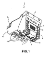
- the recording chips 4 and 5 are precisely and solidly attached to a base board 8, which has ink passages through which the recording chips 4 and 5 are supplied with the ink from an ink container unit 3.
- the contact circuit board 7, electrical wire tap 6, and base board 8 are solidly attached to a supporting member 9, which also has ink passages through which ink is supplied from the ink container unit 3 to the ink jet recording chips 4 and 5, and a filter (unshown) for removing foreign particles from the ink supplied from the ink container unit 3.
- a part of the supporting member 9 constitutes an ink container holder 10 into which the ink container unit 3 is mounted.
- Figure 2 is a schematic drawing showing the electrical signal transmission line from the main assembly of the recording apparatus to the ink jet recording chip.
- Figure 2(a) shows the state of the electrical signal transmission line when the ink container unit 3 is not in the ink container holder
- Figure 2(b) shows the state of the line when the ink container unit 3 is in the ink container holder.
- the present invention will be described with reference to one of the color ink containers (case in which ink jet recording chip 4 is driven).
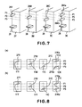
- Figure 6 is a schematic plan view of the surface of the contact circuit board 7, which is to face the ink container unit 3.
- the contact circuit board 7 is provided with electrically open (discontinuous) portions 27Y, 27M, 27C, and 27K, which are circled with solid lines in the drawing, and the positions of which correspond to those of the projections 26Y, 26M, 26C, and 26K of the ink containers of the ink container unit 3, respectively.
- the electrically open portions 27Y, 27M, 27C, and 27K are connected to the electrical signal transmission wires portions 11Y, 11M, 11C, and 11K, respectively.
- the electrical signal transmission line 31 is discontinuous between the contact points 43a and 43b.
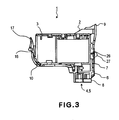
- the ink container 33 has the electrical wire portion 31c as a part of the electrical signal transmission line 31.
- the electrical wire portion 31c comes into contact with the contacts 34a and 43b through the contact 45a and 45b, allowing electrical signals to be sent from the main assembly 35 of the recording apparatus to the ink jet recording chip 4 to drive the electrothermal transducing elements.
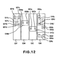
- the ink container 53Y is provided with an electrical wire portion 52Yc of the electrical signal transmission line, and a pair of contact points 65Yc and 65Yd, in addition to an electrical wire portion 51Yc and a pair of contact points 65Ya and 65Yb. Therefore, the ink jet recording chip 4 does not function unless both the electrical signal transmission line and driving voltage transmission line of the ink container 53Y become continuous. In other words, this set-up further raises the level of reliability.
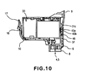
- the ink container 207 is firmly held against the supporting member 205, and the receptacle in the ink container holder 208, by the locking claw 103 and the projection of the latching lever 104. Further, the ink container 207 is kept pressured toward the contact circuit board 204 by the resiliency of the latching lever 104.
- designated by a referential number 102 is a piece of electrical wire.
- the electrical wire 102 for the ink container 207 is a piece of flexible wire having the contact points to be placed in contact with the contact circuit board 204, and is pasted on the ink container 207.
Landscapes
- Ink Jet (AREA)
- Particle Formation And Scattering Control In Inkjet Printers (AREA)
Claims (8)
- Cartouche de tête d'enregistrement (1) comprenant :une tête d'enregistrement (2) comportant une puce d'enregistrement de jet d'encre (4, 5) pour être pilotée par une tension de pilotage délivrée par un conducteur isolé de câblage de tension de pilotage et par un signal électrique délivré par un conducteur isolé de câblage de signal électrique pour éjecter l'encre ;un réservoir d'encre (3) contenant de l'encre et pouvant être monté de façon amovible sur la tête d'enregistrement (2) ; caractérisée en ce queau moins l'un dudit conducteur isolé de câblage de tension de pilotage et dudit conducteur isolé de câblage de signal électrique comprend une partie électriquement ouverte, et ledit réservoir d'encre (3) comprend un élément de connexion au niveau d'une position faisant face à la partie électriquement ouverte comportant la partie électriquement ouverte, et en ce que, lorsque le réservoir d'encre (3) est monté sur ladite cartouche de tête d'enregistrement (1), la partie électriquement ouverte est fermée par l'élément de connexion pour établir une connexion électrique.
- Cartouche de tête d'enregistrement (1) selon la revendication 1, dans laquelle ladite cartouche comprend une pluralité de tels dits réservoirs d'encre (3) pour différentes couleurs, et dans laquelle l'un et l'autre desdits deux conducteurs isolés de câblage de tension de pilotage et de câblage de signal électrique ont ladite partie électriquement ouverte qui dépend de la couleur des encres contenues dans lesdits réservoirs (3).
- Cartouche de tête d'enregistrement (1) selon la revendication 1, dans laquelle ladite cartouche comprend une pluralité de tels dits réservoirs d'encre (3) pour différentes couleurs, et au moins une des positions et des configurations desdites parties électriquement ouvertes desdits réservoirs d'encre (3) est particulière à la couleur des encres contenues en leur sein.
- Cartouche de tête d'enregistrement (2) selon la revendication 1, dans laquelle ladite partie électriquement ouverte est constituée par deux contacts électriquement isolés et un commutateur (25) relié à un desdits contacts, dans laquelle ledit réservoir d'encre (3) comporte une saillie au niveau d'une position faisant face audit commutateur (25), et dans laquelle, lorsque ledit réservoir d'encre (3) est monté sur ladite cartouche de tête d'enregistrement (1), ledit commutateur (25) est enfoncé par ladite partie en saillie pour entrer en contact avec l'autre dit contact de sorte que la partie électriquement ouverte est électriquement fermée.
- Cartouche de tête d'enregistrement (1) selon la revendication 1, dans laquelle ladite partie électriquement ouverte est constituée par deux contacts électriquement isolés, et ledit réservoir d'encre (3) comporte un conducteur isolé de câblage au niveau d'une position faisant face auxdits deux contacts, et dans laquelle, lorsque ledit réservoir d'encre (3) est monté sur ladite cartouche de tête d'enregistrement (1), le conducteur isolé de câblage entre en contact avec lesdits deux contacts pour fermer ladite partie électriquement ouverte.
- Dispositif d'enregistrement comprenant ladite cartouche de tête d'enregistrement (1) définie dans l'une quelconque des revendications 1 à 5,
dans lequel, lors de la détection de la présence ou de l'absence de conduction électrique au niveau de la partie électriquement ouverte de ladite cartouche de tête d'enregistrement (1), la présence ou l'absence d'un réservoir d'encre monté (3) qui doit fermer ladite partie électriquement ouverte peut être déterminée. - Dispositif selon la revendication 6, dans lequel, lorsque ladite partie électriquement ouverte n'est pas discriminée comme étant fermée, une opération de régénération de ladite tête d'enregistrement (2) n'est pas effectuée.
- Cartouche de tête d'enregistrement (1) selon la revendication 5, dans laquelle un conducteur isolé de câblage prévu dans ledit réservoir d'encre (3) a une configuration commune dans une étape non traitée, et la particularité est réalisée par usinage ou par usinage au laser.
Applications Claiming Priority (4)
| Application Number | Priority Date | Filing Date | Title |
|---|---|---|---|
| JP2003397296 | 2003-11-27 | ||
| JP2003397296 | 2003-11-27 | ||
| JP2004308524A JP4484664B2 (ja) | 2003-11-27 | 2004-10-22 | 記録ヘッドカートリッジ |
| JP2004308524 | 2004-10-22 |
Publications (2)
| Publication Number | Publication Date |
|---|---|
| EP1535744A1 EP1535744A1 (fr) | 2005-06-01 |
| EP1535744B1 true EP1535744B1 (fr) | 2008-01-16 |
Family
ID=34467825
Family Applications (1)
| Application Number | Title | Priority Date | Filing Date |
|---|---|---|---|
| EP04028000A Expired - Lifetime EP1535744B1 (fr) | 2003-11-27 | 2004-11-25 | Tête jet d'encre, et réservoir d'encre |
Country Status (11)
| Country | Link |
|---|---|
| US (1) | US7293865B2 (fr) |
| EP (1) | EP1535744B1 (fr) |
| JP (1) | JP4484664B2 (fr) |
| KR (1) | KR100704812B1 (fr) |
| CN (1) | CN1621232A (fr) |
| AT (1) | ATE383953T1 (fr) |
| AU (1) | AU2004233491B2 (fr) |
| CA (1) | CA2488253C (fr) |
| DE (1) | DE602004011306T2 (fr) |
| SG (1) | SG112112A1 (fr) |
| TW (1) | TWI243103B (fr) |
Families Citing this family (16)
| Publication number | Priority date | Publication date | Assignee | Title |
|---|---|---|---|---|
| JP4886586B2 (ja) * | 2006-05-09 | 2012-02-29 | キヤノン株式会社 | 液体収納容器、ヘッドカートリッジ、インクジェット記録装置、および液体収納容器の攪拌方法 |
| JP5011922B2 (ja) | 2006-09-29 | 2012-08-29 | ブラザー工業株式会社 | インクカートリッジ及びインクジェット記録システム |
| CN101804738B (zh) * | 2010-05-18 | 2012-04-11 | 珠海艾派克微电子有限公司 | 墨盒芯片、墨盒、成像装置和成像装置墨盒更换方法 |
| JP5880286B2 (ja) | 2011-08-24 | 2016-03-08 | セイコーエプソン株式会社 | 液体容器 |
| CN102602148B (zh) * | 2012-03-13 | 2014-12-17 | 新会江裕信息产业有限公司 | 一种打印机 |
| US9239134B1 (en) * | 2014-02-04 | 2016-01-19 | Colt International Clothing Inc. | Flexible and adaptable light harness and wiring |
| JP6498098B2 (ja) | 2015-10-30 | 2019-04-10 | キヤノン株式会社 | 記録装置および液体収容部材 |
| JP6700719B2 (ja) | 2015-10-30 | 2020-05-27 | キヤノン株式会社 | 液体吐出装置及びヘッド |
| JP2017081083A (ja) | 2015-10-30 | 2017-05-18 | キヤノン株式会社 | 液体吐出装置、ヘッド及び液体充填方法 |
| JP6602160B2 (ja) | 2015-10-30 | 2019-11-06 | キヤノン株式会社 | 液体吐出装置及びヘッド |
| JP7246978B2 (ja) | 2019-03-15 | 2023-03-28 | キヤノン株式会社 | 液体吐出装置及び液体充填方法 |
| JP7391637B2 (ja) | 2019-12-03 | 2023-12-05 | キヤノン株式会社 | 液体貯蔵装置および液体充填方法 |
| JP7532055B2 (ja) | 2020-03-24 | 2024-08-13 | キヤノン株式会社 | 液体供給装置 |
| JP7504641B2 (ja) | 2020-03-27 | 2024-06-24 | キヤノン株式会社 | 液体吐出装置 |
| JP7520574B2 (ja) | 2020-05-22 | 2024-07-23 | キヤノン株式会社 | 液体カートリッジおよび液体吐出装置 |
| JP7434235B2 (ja) | 2021-09-17 | 2024-02-20 | キヤノン株式会社 | 液体吐出装置およびカートリッジ |
Family Cites Families (26)
| Publication number | Priority date | Publication date | Assignee | Title |
|---|---|---|---|---|
| DE69034212T2 (de) | 1989-08-05 | 2006-07-13 | Canon K.K. | Tintenstrahlaufzeichnungsgerät und Tintenkassette dafür |
| JPH0550662A (ja) * | 1991-08-28 | 1993-03-02 | Canon Inc | カラー記録装置 |
| JPH05169673A (ja) | 1991-12-19 | 1993-07-09 | Canon Inc | インクジェット記録装置およびヘッドカートリッジ |
| EP0860285B1 (fr) | 1991-12-11 | 2002-03-06 | Canon Kabushiki Kaisha | Cartouche à jet d'encre |
| US6170939B1 (en) | 1992-07-31 | 2001-01-09 | Canon Kabushiki Kaisha | Liquid storing container for recording apparatus |
| DK0585705T3 (da) * | 1992-08-28 | 1999-07-26 | Bayer Ag | Anvendelse af monoklone anti-TNF-antistoffer til behandling af bakteriel meningitis |
| JP3253153B2 (ja) | 1992-10-20 | 2002-02-04 | キヤノン株式会社 | インクジェットヘッドカートリッジ及び該カートリッジを備えたインクジェット装置 |
| JPH06262771A (ja) * | 1993-03-16 | 1994-09-20 | Canon Inc | インクジェット記録装置 |
| PT1219446E (pt) | 1993-07-20 | 2005-06-30 | Canon Kk | Aparelho de gravacao de jacto de tinta que utiliza a unidade de gravacao com cartucho de tinta que tem um elemento que inclui tinta |
| JP3432869B2 (ja) | 1993-10-29 | 2003-08-04 | ヤンマー農機株式会社 | 非破壊選果方法 |
| JP3221210B2 (ja) | 1994-02-07 | 2001-10-22 | 富士ゼロックス株式会社 | インクタンク |
| JPH07309015A (ja) | 1994-05-19 | 1995-11-28 | Canon Inc | インクジェットユニットおよびインクジェット記録装置 |
| ES2317134T3 (es) | 1994-08-24 | 2009-04-16 | Canon Kabushiki Kaisha | Contenedor de tinta para impresora por chorros de tinta. |
| JPH08169122A (ja) * | 1994-12-16 | 1996-07-02 | Ricoh Co Ltd | 画像形成装置 |
| JPH0939265A (ja) | 1995-07-29 | 1997-02-10 | Seiko Epson Corp | プリンタにおけるインクカートリッヂ並びにその識別装置 |
| JP3537564B2 (ja) * | 1995-11-10 | 2004-06-14 | 株式会社リコー | インクジェット記録装置 |
| KR0155256B1 (ko) * | 1996-04-09 | 1998-12-01 | 김광호 | 잉크젯 프린터의 노즐 검사 방법 |
| JP3295339B2 (ja) | 1996-08-30 | 2002-06-24 | キヤノン株式会社 | インクタンク、ホルダー、インクジェットカートリッジおよびキャップ |
| JPH1191141A (ja) * | 1997-09-19 | 1999-04-06 | Seiko Epson Corp | インクジェット式記録装置 |
| JPH11138818A (ja) * | 1997-11-14 | 1999-05-25 | Canon Inc | ヘッド、該ヘッドを搭載した記録装置、ヘッドの個体識別方法およびヘッドへの識別情報の付与方法 |
| DE19839225A1 (de) | 1998-08-28 | 2000-03-02 | Siemens Nixdorf Inf Syst | Tintenstrahldrucker und Wechselbehälter für Drucktinte |
| JP4266263B2 (ja) | 2000-01-12 | 2009-05-20 | 株式会社リコー | インクジェット記録装置及び画像形成装置 |
| JP2002120379A (ja) * | 2000-10-16 | 2002-04-23 | Seiko Epson Corp | インクカートリッジ及びインクジェット式記録装置 |
| JP4678801B2 (ja) * | 2000-11-01 | 2011-04-27 | キヤノン株式会社 | 温度検出回路及び該回路を備えた記録装置 |
| JP3880411B2 (ja) * | 2001-01-31 | 2007-02-14 | キヤノン株式会社 | 記録装置 |
| JP2003305843A (ja) * | 2002-04-12 | 2003-10-28 | Seiko Epson Corp | インクジェット式記録装置 |
-
2004
- 2004-10-22 JP JP2004308524A patent/JP4484664B2/ja not_active Expired - Fee Related
- 2004-11-24 SG SG200407937A patent/SG112112A1/en unknown
- 2004-11-24 US US10/995,359 patent/US7293865B2/en not_active Expired - Fee Related
- 2004-11-24 TW TW093136171A patent/TWI243103B/zh not_active IP Right Cessation
- 2004-11-24 CA CA002488253A patent/CA2488253C/fr not_active Expired - Fee Related
- 2004-11-25 EP EP04028000A patent/EP1535744B1/fr not_active Expired - Lifetime
- 2004-11-25 DE DE602004011306T patent/DE602004011306T2/de not_active Expired - Lifetime
- 2004-11-25 AT AT04028000T patent/ATE383953T1/de not_active IP Right Cessation
- 2004-11-25 AU AU2004233491A patent/AU2004233491B2/en not_active Ceased
- 2004-11-26 KR KR1020040097819A patent/KR100704812B1/ko not_active Expired - Fee Related
- 2004-11-29 CN CNA2004100955432A patent/CN1621232A/zh active Pending
Also Published As
| Publication number | Publication date |
|---|---|
| TWI243103B (en) | 2005-11-11 |
| JP4484664B2 (ja) | 2010-06-16 |
| AU2004233491A1 (en) | 2005-06-16 |
| SG112112A1 (en) | 2005-06-29 |
| DE602004011306T2 (de) | 2009-01-15 |
| DE602004011306D1 (de) | 2008-03-06 |
| CA2488253C (fr) | 2009-02-10 |
| JP2005178362A (ja) | 2005-07-07 |
| US20050117002A1 (en) | 2005-06-02 |
| CA2488253A1 (fr) | 2005-05-27 |
| EP1535744A1 (fr) | 2005-06-01 |
| AU2004233491B2 (en) | 2006-10-19 |
| ATE383953T1 (de) | 2008-02-15 |
| US7293865B2 (en) | 2007-11-13 |
| TW200523128A (en) | 2005-07-16 |
| CN1621232A (zh) | 2005-06-01 |
| KR20050051568A (ko) | 2005-06-01 |
| KR100704812B1 (ko) | 2007-04-10 |
Similar Documents
| Publication | Publication Date | Title |
|---|---|---|
| CA2488253C (fr) | Tete d'ecriture a jet d'encre, et contenant d'encre | |
| EP0992348B1 (fr) | Cartouche d'impression modulaire pour usage dans des systèmes d'impression à jet d'encre | |
| EP2527153B1 (fr) | Modulation domestique d'encre combinée pour cartouche d'encre | |
| KR100460241B1 (ko) | 액체 용기 및 기록 장치 | |
| KR100357680B1 (ko) | 잉크 탱크, 잉크 공급 시스템, 잉크 제트 헤드 카트리지 및 잉크 제트 기록 장치 | |
| EP2186645B1 (fr) | Tête d'impression par jet d'encre et imprimante l'utilisant | |
| KR100453425B1 (ko) | 교체가능한잉크저장용기와그삽입방법 | |
| US6464338B1 (en) | Ink jet head with separable tank holding member and recording unit | |
| EP0418817B1 (fr) | Tête d'enregistrement à jet d'encre et appareil d'enregistrement à jet d'encre utilisant celle-ci | |
| EP1547783B1 (fr) | Réservoir de liquide | |
| EP0546544A2 (fr) | Appareil d'enregistrement à jet d'encre et son mécanisme de chariot | |
| US6074041A (en) | Ink jet recording head having an electric discharge path for releasing static electricity and recording apparatus using same | |
| KR20050067050A (ko) | 액체 용기, 액체 공급 시스템, 그 제조 방법, 그 회로기판 및 액체 내장 카트리지 | |
| KR20010013265A (ko) | 교환가능한 잉크 용기 및 오프-축형 프린팅 시스템과오프-축형 프린팅 시스템내로 잉크 용기를 삽입하는 방법 | |
| US6203149B1 (en) | Ink jet cartridge, ink jet apparatus and ink container | |
| AU660746B2 (en) | Ink jet recording head, ink jet recording head cartridge and recording apparatus using same | |
| HK1072917A (en) | Ink jet recording head, and ink container | |
| JPH0986012A (ja) | インクジェット記録装置 | |
| JPH10226060A (ja) | インクジェット記録装置 | |
| HK1095792B (en) | Ink jet printing head and ink jet printing apparatus using the same | |
| HK1144156A (en) | Ink jet printing head and ink jet printing apparatus using the same |
Legal Events
| Date | Code | Title | Description |
|---|---|---|---|
| PUAI | Public reference made under article 153(3) epc to a published international application that has entered the european phase |
Free format text: ORIGINAL CODE: 0009012 |
|
| 17P | Request for examination filed |
Effective date: 20041125 |
|
| AK | Designated contracting states |
Kind code of ref document: A1 Designated state(s): AT BE BG CH CY CZ DE DK EE ES FI FR GB GR HU IE IS IT LI LU MC NL PL PT RO SE SI SK TR |
|
| AX | Request for extension of the european patent |
Extension state: AL HR LT LV MK YU |
|
| REG | Reference to a national code |
Ref country code: HK Ref legal event code: DE Ref document number: 1072917 Country of ref document: HK |
|
| AKX | Designation fees paid |
Designated state(s): AT BE BG CH CY CZ DE DK EE ES FI FR GB GR HU IE IS IT LI LU MC NL PL PT RO SE SI SK TR |
|
| GRAP | Despatch of communication of intention to grant a patent |
Free format text: ORIGINAL CODE: EPIDOSNIGR1 |
|
| GRAS | Grant fee paid |
Free format text: ORIGINAL CODE: EPIDOSNIGR3 |
|
| GRAA | (expected) grant |
Free format text: ORIGINAL CODE: 0009210 |
|
| AK | Designated contracting states |
Kind code of ref document: B1 Designated state(s): AT BE BG CH CY CZ DE DK EE ES FI FR GB GR HU IE IS IT LI LU MC NL PL PT RO SE SI SK TR |
|
| REG | Reference to a national code |
Ref country code: GB Ref legal event code: FG4D |
|
| REG | Reference to a national code |
Ref country code: CH Ref legal event code: EP |
|
| REG | Reference to a national code |
Ref country code: IE Ref legal event code: FG4D |
|
| REF | Corresponds to: |
Ref document number: 602004011306 Country of ref document: DE Date of ref document: 20080306 Kind code of ref document: P |
|
| PG25 | Lapsed in a contracting state [announced via postgrant information from national office to epo] |
Ref country code: NL Free format text: LAPSE BECAUSE OF FAILURE TO SUBMIT A TRANSLATION OF THE DESCRIPTION OR TO PAY THE FEE WITHIN THE PRESCRIBED TIME-LIMIT Effective date: 20080116 |
|
| NLV1 | Nl: lapsed or annulled due to failure to fulfill the requirements of art. 29p and 29m of the patents act | ||
| PG25 | Lapsed in a contracting state [announced via postgrant information from national office to epo] |
Ref country code: ES Free format text: LAPSE BECAUSE OF FAILURE TO SUBMIT A TRANSLATION OF THE DESCRIPTION OR TO PAY THE FEE WITHIN THE PRESCRIBED TIME-LIMIT Effective date: 20080427 Ref country code: LI Free format text: LAPSE BECAUSE OF FAILURE TO SUBMIT A TRANSLATION OF THE DESCRIPTION OR TO PAY THE FEE WITHIN THE PRESCRIBED TIME-LIMIT Effective date: 20080116 Ref country code: IS Free format text: LAPSE BECAUSE OF FAILURE TO SUBMIT A TRANSLATION OF THE DESCRIPTION OR TO PAY THE FEE WITHIN THE PRESCRIBED TIME-LIMIT Effective date: 20080516 Ref country code: CH Free format text: LAPSE BECAUSE OF FAILURE TO SUBMIT A TRANSLATION OF THE DESCRIPTION OR TO PAY THE FEE WITHIN THE PRESCRIBED TIME-LIMIT Effective date: 20080116 Ref country code: FI Free format text: LAPSE BECAUSE OF FAILURE TO SUBMIT A TRANSLATION OF THE DESCRIPTION OR TO PAY THE FEE WITHIN THE PRESCRIBED TIME-LIMIT Effective date: 20080116 |
|
| REG | Reference to a national code |
Ref country code: CH Ref legal event code: PL |
|
| PG25 | Lapsed in a contracting state [announced via postgrant information from national office to epo] |
Ref country code: AT Free format text: LAPSE BECAUSE OF FAILURE TO SUBMIT A TRANSLATION OF THE DESCRIPTION OR TO PAY THE FEE WITHIN THE PRESCRIBED TIME-LIMIT Effective date: 20080116 Ref country code: BG Free format text: LAPSE BECAUSE OF FAILURE TO SUBMIT A TRANSLATION OF THE DESCRIPTION OR TO PAY THE FEE WITHIN THE PRESCRIBED TIME-LIMIT Effective date: 20080416 |
|
| ET | Fr: translation filed | ||
| PG25 | Lapsed in a contracting state [announced via postgrant information from national office to epo] |
Ref country code: SI Free format text: LAPSE BECAUSE OF FAILURE TO SUBMIT A TRANSLATION OF THE DESCRIPTION OR TO PAY THE FEE WITHIN THE PRESCRIBED TIME-LIMIT Effective date: 20080116 Ref country code: PT Free format text: LAPSE BECAUSE OF FAILURE TO SUBMIT A TRANSLATION OF THE DESCRIPTION OR TO PAY THE FEE WITHIN THE PRESCRIBED TIME-LIMIT Effective date: 20080616 Ref country code: PL Free format text: LAPSE BECAUSE OF FAILURE TO SUBMIT A TRANSLATION OF THE DESCRIPTION OR TO PAY THE FEE WITHIN THE PRESCRIBED TIME-LIMIT Effective date: 20080116 Ref country code: BE Free format text: LAPSE BECAUSE OF FAILURE TO SUBMIT A TRANSLATION OF THE DESCRIPTION OR TO PAY THE FEE WITHIN THE PRESCRIBED TIME-LIMIT Effective date: 20080116 |
|
| PG25 | Lapsed in a contracting state [announced via postgrant information from national office to epo] |
Ref country code: SE Free format text: LAPSE BECAUSE OF FAILURE TO SUBMIT A TRANSLATION OF THE DESCRIPTION OR TO PAY THE FEE WITHIN THE PRESCRIBED TIME-LIMIT Effective date: 20080416 Ref country code: CZ Free format text: LAPSE BECAUSE OF FAILURE TO SUBMIT A TRANSLATION OF THE DESCRIPTION OR TO PAY THE FEE WITHIN THE PRESCRIBED TIME-LIMIT Effective date: 20080116 Ref country code: DK Free format text: LAPSE BECAUSE OF FAILURE TO SUBMIT A TRANSLATION OF THE DESCRIPTION OR TO PAY THE FEE WITHIN THE PRESCRIBED TIME-LIMIT Effective date: 20080116 Ref country code: SK Free format text: LAPSE BECAUSE OF FAILURE TO SUBMIT A TRANSLATION OF THE DESCRIPTION OR TO PAY THE FEE WITHIN THE PRESCRIBED TIME-LIMIT Effective date: 20080116 |
|
| PLBE | No opposition filed within time limit |
Free format text: ORIGINAL CODE: 0009261 |
|
| STAA | Information on the status of an ep patent application or granted ep patent |
Free format text: STATUS: NO OPPOSITION FILED WITHIN TIME LIMIT |
|
| PG25 | Lapsed in a contracting state [announced via postgrant information from national office to epo] |
Ref country code: RO Free format text: LAPSE BECAUSE OF FAILURE TO SUBMIT A TRANSLATION OF THE DESCRIPTION OR TO PAY THE FEE WITHIN THE PRESCRIBED TIME-LIMIT Effective date: 20080116 |
|
| 26N | No opposition filed |
Effective date: 20081017 |
|
| PG25 | Lapsed in a contracting state [announced via postgrant information from national office to epo] |
Ref country code: EE Free format text: LAPSE BECAUSE OF FAILURE TO SUBMIT A TRANSLATION OF THE DESCRIPTION OR TO PAY THE FEE WITHIN THE PRESCRIBED TIME-LIMIT Effective date: 20080116 |
|
| PG25 | Lapsed in a contracting state [announced via postgrant information from national office to epo] |
Ref country code: MC Free format text: LAPSE BECAUSE OF NON-PAYMENT OF DUE FEES Effective date: 20081130 |
|
| PG25 | Lapsed in a contracting state [announced via postgrant information from national office to epo] |
Ref country code: CY Free format text: LAPSE BECAUSE OF FAILURE TO SUBMIT A TRANSLATION OF THE DESCRIPTION OR TO PAY THE FEE WITHIN THE PRESCRIBED TIME-LIMIT Effective date: 20080116 |
|
| PG25 | Lapsed in a contracting state [announced via postgrant information from national office to epo] |
Ref country code: IT Free format text: LAPSE BECAUSE OF FAILURE TO SUBMIT A TRANSLATION OF THE DESCRIPTION OR TO PAY THE FEE WITHIN THE PRESCRIBED TIME-LIMIT Effective date: 20080116 |
|
| PG25 | Lapsed in a contracting state [announced via postgrant information from national office to epo] |
Ref country code: IE Free format text: LAPSE BECAUSE OF NON-PAYMENT OF DUE FEES Effective date: 20081125 |
|
| PG25 | Lapsed in a contracting state [announced via postgrant information from national office to epo] |
Ref country code: LU Free format text: LAPSE BECAUSE OF NON-PAYMENT OF DUE FEES Effective date: 20081125 Ref country code: HU Free format text: LAPSE BECAUSE OF FAILURE TO SUBMIT A TRANSLATION OF THE DESCRIPTION OR TO PAY THE FEE WITHIN THE PRESCRIBED TIME-LIMIT Effective date: 20080717 |
|
| PG25 | Lapsed in a contracting state [announced via postgrant information from national office to epo] |
Ref country code: TR Free format text: LAPSE BECAUSE OF FAILURE TO SUBMIT A TRANSLATION OF THE DESCRIPTION OR TO PAY THE FEE WITHIN THE PRESCRIBED TIME-LIMIT Effective date: 20080116 |
|
| PG25 | Lapsed in a contracting state [announced via postgrant information from national office to epo] |
Ref country code: GR Free format text: LAPSE BECAUSE OF FAILURE TO SUBMIT A TRANSLATION OF THE DESCRIPTION OR TO PAY THE FEE WITHIN THE PRESCRIBED TIME-LIMIT Effective date: 20080417 |
|
| REG | Reference to a national code |
Ref country code: HK Ref legal event code: WD Ref document number: 1072917 Country of ref document: HK |
|
| PGFP | Annual fee paid to national office [announced via postgrant information from national office to epo] |
Ref country code: FR Payment date: 20131125 Year of fee payment: 10 |
|
| REG | Reference to a national code |
Ref country code: FR Ref legal event code: ST Effective date: 20150731 |
|
| PG25 | Lapsed in a contracting state [announced via postgrant information from national office to epo] |
Ref country code: FR Free format text: LAPSE BECAUSE OF NON-PAYMENT OF DUE FEES Effective date: 20141201 |
|
| PGFP | Annual fee paid to national office [announced via postgrant information from national office to epo] |
Ref country code: GB Payment date: 20161125 Year of fee payment: 13 Ref country code: DE Payment date: 20161130 Year of fee payment: 13 |
|
| REG | Reference to a national code |
Ref country code: DE Ref legal event code: R119 Ref document number: 602004011306 Country of ref document: DE |
|
| GBPC | Gb: european patent ceased through non-payment of renewal fee |
Effective date: 20171125 |
|
| PG25 | Lapsed in a contracting state [announced via postgrant information from national office to epo] |
Ref country code: DE Free format text: LAPSE BECAUSE OF NON-PAYMENT OF DUE FEES Effective date: 20180602 |
|
| PG25 | Lapsed in a contracting state [announced via postgrant information from national office to epo] |
Ref country code: GB Free format text: LAPSE BECAUSE OF NON-PAYMENT OF DUE FEES Effective date: 20171125 |