EP1534522B1 - Systemes d'encrage de machines d'impression rotative - Google Patents
Systemes d'encrage de machines d'impression rotative Download PDFInfo
- Publication number
- EP1534522B1 EP1534522B1 EP03794782A EP03794782A EP1534522B1 EP 1534522 B1 EP1534522 B1 EP 1534522B1 EP 03794782 A EP03794782 A EP 03794782A EP 03794782 A EP03794782 A EP 03794782A EP 1534522 B1 EP1534522 B1 EP 1534522B1
- Authority
- EP
- European Patent Office
- Prior art keywords
- roller
- ink
- doctor blade
- inking unit
- unit according
- Prior art date
- Legal status (The legal status is an assumption and is not a legal conclusion. Google has not performed a legal analysis and makes no representation as to the accuracy of the status listed.)
- Expired - Lifetime
Links
- 239000007921 spray Substances 0.000 claims 1
- 239000003973 paint Substances 0.000 description 9
- 230000005484 gravity Effects 0.000 description 4
- 238000007774 anilox coating Methods 0.000 description 2
- 239000000758 substrate Substances 0.000 description 2
- 238000003854 Surface Print Methods 0.000 description 1
- 238000011109 contamination Methods 0.000 description 1
- 230000004907 flux Effects 0.000 description 1
- -1 web Substances 0.000 description 1
Images
Classifications
-
- B—PERFORMING OPERATIONS; TRANSPORTING
- B41—PRINTING; LINING MACHINES; TYPEWRITERS; STAMPS
- B41F—PRINTING MACHINES OR PRESSES
- B41F31/00—Inking arrangements or devices
- B41F31/02—Ducts, containers, supply or metering devices
Definitions
- the invention relates to inking units of rotary printing machines according to the preamble of claim 1.
- the layout DE 1 214 704 is an inking unit of a rotary printing machine with an ink supply to a central roller known, wherein a first and a second inking roller to be inked on a forme cylinder are provided and color is transferred over a plurality of ink flows from the central roller to the forme cylinder.
- a first ink flow leads from the central roller to a rubbing roller which splits the ink flow into a main flow and a tributary by transferring the ink to both inking rollers, the main flow leading to the second, ie to the downstream in the direction of rotation of the forme inking roller , After another rotation, the friction roller transfers color to the first in the direction of rotation of the forme inking roller.
- WO 98151500 A1 is an inking unit of a rotary printing machine with an ink supply to a central roller known, wherein two engageable with a form to be inked inking rollers are provided and color is transmitted via two mutually separate color flows from the central roller to the forme cylinder.
- the two inking rollers are on the one hand inked directly from the central roller and, on the other hand, indirectly again by ink transfer rollers arranged between the central roller and each inking roller.
- This inking unit is also behind heavy, because in this roller arrangement, the larger amount of ink on the second in the direction of rotation of the forme cylinder, that is transmitted to the downstream in the direction of rotation of the forme inking roller.
- the invention has for its object to provide inking units of rotary printing machines.
- the advantages achieved by the invention are in particular that the proposed inking with comparatively few, z. B. manages with five rollers for transferring and distributing color and thus can be realized inexpensively. Nevertheless, enough inking rollers, z. B. three, available to apply a sufficient amount of ink on a forme cylinder even at high printing speeds. Characterized in that the central roller and the forme cylinder according to the invention have an opposite direction of rotation, there is a front-heavy inking, in which the larger amount of ink on the first in the direction of rotation of the forme cylinder, that is transmitted to the first in the direction of rotation of the forme inking roller.
- this inking unit does not tend to stencil, i. H. in full areas, other co-printing parts of the printing form do not form again, because the applied in the main flow on the form cylinder color is smoothed before being transferred to the transfer cylinder by the second inking roller.
- the ink transfer rollers are preferably formed iridescent.
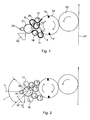
- Both figures show an inking unit of a rotary printing machine with an ink supply to a central roller 01, the z. B. is formed as an anilox roller 01.
- the central roller 01 is thus in the inking unit, the first, preferably continuous ink-absorbing roller 01 and serves subsequent, standing in operative connection with them rollers 08; 09 as a color source.
- the ink supply to the central roller 01 is z. B. from a paint box 02, from the particular by means of several engageable with the central roller 01 doctor blade 18; 19 color is transferred to the lateral surface of the central roller 01.
- the squeegee 18; 19 belong to a preferably laterally on the central roller 01st arranged in the axial direction chambered doctor blade 03 with a doctoring chamber, wherein in the direction of rotation of the central roller 01 a working doctor blade 18 at the bottom of the doctor chamber, ie substantially in the direction of gravity G and a closing blade 19 at the top of the doctor chamber, ie substantially against the direction of gravity G is arranged.
- the doctor chamber is filled with paint, the ink is usually pressurized.
- the direction of rotation of the central roller 01 is selected such that the central roller 01 passes through at least the working doctor blade 18 substantially in the direction of the gravitational force G during the paint application by the arrangement of the chambered doctor blade 03 which is essentially horizontal with respect to the central roller 01.
- the working doctor blade 18 is therefore advantageously within a starting from a center M of the central roller 01, extending from one passing through the center M of the central roller 01 horizontal H on both sides with less than 45 °, preferably with less than 15 ° opening angle ⁇ at the central roller 01 employed.
- two color flows A run separately from one another; B to a inked forme cylinder 04, wherein the forme cylinder 04 transmits the paint applied to it on a transfer cylinder 06, in turn, a substrate 07, z. B. a web 07, in particular a paper web 07 printed.
- On the lateral surface of the forme cylinder 04 at least one printing plate (not shown) is clamped, which is held in a holding device 14 arranged on the circumference of the forme cylinder 04.
- two printing plates can be applied in the direction of the circumference of the forme cylinder 04.
- inking unit is in each of the two aforementioned color flows A; B in each case an adjustable to the central roller 01 ink transfer roller 08; 09 provided, in turn, with at least one simultaneously to the forme cylinder 04 and to one of Ink transfer rollers 08; 09 adjustable inking roller 11; 12; 13 interact.
- B at least one simultaneously to the central roller 01 and at least one of the inking rollers 11; 12; 13 engageable ink transfer roller 08; 09 be provided.
- inking rollers 11; 12; 13 are provided, wherein in the direction of rotation of the forme cylinder 04, a first inking roller 11 is disposed in front of a second inking roller 12 and a third inking roller 13 is provided, both to the forme cylinder 04 and to one of the ink transfer rollers 08; 09, preferably to the second ink transfer roller 09 is adjustable.
- the first ink transfer roller 08 is arranged in front of the second ink transfer roller 09, so that the first ink transfer roller 08 receives from the central roller 01, the larger amount of ink, because in the direction of rotation of the central roller 01 as the first of the chambered doctor blade 03 on the Surface of the central roller 01 absorbs applied paint according to the laws of color splitting. Only the remaining after this first color transfer on the lateral surface of the central roller 01 amount of ink is then at a further rotation of the central roller 01 for an at least partial transfer to the second ink transfer roller 09 is available.
- the direction of rotation of the forme cylinder 04 and the transfer cylinder 06 and the rollers 01; 08; 09; 11; 12; 13 is indicated in each case by an arrow in the two figures.
- the central roller 01 and the forme cylinder 04 have an opposite direction of rotation.
- the ink flow A to that inking roller 11, which is employed in the direction of rotation of the forme cylinder 04 at this first transmits a larger compared to the other ink flow B amount of ink.
- the inking unit is therefore front-heavy.
- the quantitatively larger color is due to the direction of rotation of the forme 04 downstream inking rollers 12; 13 smoothed, so the proposed inking is not stenciled.
- the ink flow A passing over the first ink transfer roller 08 and the first inking roller 11 thus forms the main flow A for ink transfer from the central roller 01 to the forme cylinder 04, whereas the ink flow B forms a first tributary B, of which in the particular example shown third inking roller 13 employed both on the second ink transfer roller 09 and on the forme cylinder 04, a second tributary C is branched off.
- a uniform application of paint on the lateral surface of the forme cylinder 04 can also be promoted by at least one inking roller 11; 12; 13 or a paint transfer roller 08; 09 at least slightly changed.
- at least the second inking roller 12 or the third inking roller 13 change to rub the inking.
- at least one of the ink transfer rollers 08; 09 adjustable friction roller 16; 17 be provided.
- the ink transfer rollers 08; 09, the inking rollers 11; 12; 13 or the at least one rubbing roller 16; 17 to the standing in operative connection with them rollers 01; 08; 09; 11; 12; 13; 16; 17 or to the forme cylinder 04 are selectively adjustable or disabled.
- the central roller 01, the ink transfer rollers 08; 09, the inking rollers 11; 12; 13 or the at least one rubbing roller 16; 17 at least partially an oleophilic lateral surface.
Claims (12)
- Groupe d'encrage d'une machine à imprimer rotative, avec un rouleau tramé (01) avec au moins deux flux d'encre (A ; B), s'étendant séparément l'un de l'autre, de celui-ci à un cylindre de forme (04) à encrer, au moins une racle de travail (18) étant plaquée sur le rouleau tramé (01), caractérisé en ce que, dans chaque flux d'encre (A ; B) ne sont prévus qu'un unique rouleau de transfert d'encre (08 ; 09), susceptible d'être plaqué sur le rouleau tramé (01), et au moins un rouleau encreur (11 ; 12 ; 13), susceptible d'être plaqué simultanément sur le cylindre de forme (04) et sur l'un des rouleaux de transfert d'encre (08 ; 09), en ce que le rouleau tramé (01) et le cylindre de forme (04) présentent un sens de rotation opposé, le sens de rotation du rouleau tramé (01), dans la zone active de la racle de travail (18), étant orienté sensiblement dans le sens de la force de gravité (G).
- Groupe d'encrage selon la revendication 1, caractérisé en ce que, pour l'application d'encre sur le rouleau tramé (01), une racle à chambre (03) est plaquée sur le rouleau tramé (01), ou un dispositif de pompage d'encre, ou un dispositif de pulvérisation d'encre, applique de l'encre sur le rouleau tramé (01).
- Groupe d'encrage selon la revendication 2, caractérisé en ce que la racle de travail (18) appartient à la racle à chambre (03), la racle à chambre (03) présente au moins une racle de travail (18) et au moins une racle de fermeture (19), sachant que, en référence au sens de la force de gravité (G), la racle de travail (18) se trouve au-dessous et la racle de fermeture (19) se trouve au-dessus et à distance de la racle de travail (18), dans la direction périphérique du rouleau tramé (01), le rouleau tramé (01) présentant un sens de rotation orienté en allant de la racle de fermeture (19) à la racle de travail (18).
- Groupe d'encrage selon la revendication 1, caractérisé en ce que le rouleau tramé (01) est le premier rouleau (01) recevant l'encre, dans le groupe d'encrage.
- Groupe d'encrage selon la revendication 1, caractérisé en ce que le flux d'encre (A) au rouleau encreur (11) qui, dans le sens de rotation du cylindre de forme (04), est plaqué le premier sur celui-ci, est plaqué en premier sur celui-ci, transfère une plus grande quantité d'encre, en comparaison d'un flux d'encre (B ; C) vers un autre rouleau encreur (12 ; 13).
- Groupe d'encrage selon la revendication 1, caractérisé en ce que les rouleaux de transfert d'encre (08 ; 09) sont disposés de manière à effectuer un va et vient axial.
- Groupe d'encrage selon la revendication 1, caractérisé en ce qu'au moins un rouleau encreur (11 ; 12 ; 13) est disposé de manière à effectuer un va et vient axial.
- Groupe d'encrage selon la revendication 1, caractérisé en ce qu'est disposé de manière à effectuer un va et vient axial au moins l'un des rouleaux encreurs (12 ; 13) qui est disposé à la suite du premier rouleau encreur (11) plaqué sur le cylindre de forme (04), dans le sens de rotation du cylindre de forme (04).
- Groupe d'encrage selon la revendication 1, caractérisé en ce qu'au moins un rouleau de friction (16 ; 17), susceptible d'être plaqué sur l'un des rouleaux de transfert d'encre (08 ; 09), est prévu.
- Groupe d'encrage selon la revendication 1 ou 9, caractérisé en ce que les rouleaux de transfert d'encre (08 ; 09), les rouleaux encreurs (11 ; 12 ; 13), ou le au moins un rouleau de friction (16 ; 17), sont, au choix, susceptibles d'être plaqués sur, ou susceptibles d'être dégagés des rouleaux (01 ; 08 ; 09 ; 11 ; 12 ; 13 ; 16 ; 17) en liaison fonctionnelle avec eux, ou sur le cylindre de forme (04).
- Groupe d'encrage selon la revendication 1 ou 9, caractérisé en ce que le rouleau tramé (01), les rouleaux de transfert d'encre (08 ; 09), les rouleaux encreurs (11 ; 12 ; 13), ou le au moins un rouleau de friction (16 ; 17), présentent une surface d'enveloppe oléophile.
- Groupe d'encrage selon la revendication 1, caractérisé en ce que la racle de travail (18) est plaquée sur le rouleau tramé (01), dans les limites d'un angle d'ouverture (α) partant d'un point central (M) du rouleau tramé (01), s'ouvrant des deux côtés avec moins de 45° par rapport à une horizontale (H) passant par le point central (M) du rouleau tramé (01).
Applications Claiming Priority (5)
| Application Number | Priority Date | Filing Date | Title |
|---|---|---|---|
| DE10241783 | 2002-09-06 | ||
| DE10241783 | 2002-09-06 | ||
| DE10256173 | 2002-12-02 | ||
| DE10256173A DE10256173A1 (de) | 2002-09-06 | 2002-12-02 | Farbwerke von Rotationsdruckmaschinen |
| PCT/DE2003/002694 WO2004024451A1 (fr) | 2002-09-06 | 2003-08-09 | Systemes d'encrage de machines d'impression rotative |
Publications (2)
| Publication Number | Publication Date |
|---|---|
| EP1534522A1 EP1534522A1 (fr) | 2005-06-01 |
| EP1534522B1 true EP1534522B1 (fr) | 2009-09-30 |
Family
ID=31995055
Family Applications (1)
| Application Number | Title | Priority Date | Filing Date |
|---|---|---|---|
| EP03794782A Expired - Lifetime EP1534522B1 (fr) | 2002-09-06 | 2003-08-09 | Systemes d'encrage de machines d'impression rotative |
Country Status (3)
| Country | Link |
|---|---|
| EP (1) | EP1534522B1 (fr) |
| AU (1) | AU2003266117A1 (fr) |
| WO (1) | WO2004024451A1 (fr) |
Families Citing this family (6)
| Publication number | Priority date | Publication date | Assignee | Title |
|---|---|---|---|---|
| DE102006030057B4 (de) * | 2006-05-23 | 2009-12-24 | Koenig & Bauer Aktiengesellschaft | Farbwerk einer Rotationsdruckmaschine |
| ATE456456T1 (de) | 2006-05-23 | 2010-02-15 | Koenig & Bauer Ag | Anordnungen in einem druckwerk einer rotationsdruckmaschine |
| EP2019752B1 (fr) | 2006-05-23 | 2009-07-29 | König & Bauer AG | Mécanisme d'encrage de presse rotative comprenant un cylindre porte-film |
| CN101495315B (zh) * | 2006-05-23 | 2011-02-02 | 柯尼格及包尔公开股份有限公司 | 具有油膜传墨辊的轮转印刷机输墨装置 |
| DE102006042590B4 (de) * | 2006-09-11 | 2009-12-17 | Koenig & Bauer Aktiengesellschaft | Rotationsdruckmaschine mit mindestens einem eine Farbstromtrennwalze aufweisenden Farbwerk |
| CN102059852B (zh) * | 2010-11-17 | 2012-12-05 | 东莞市中崎机械有限公司 | 转轮印刷机印刷单元的传墨系统 |
Family Cites Families (6)
| Publication number | Priority date | Publication date | Assignee | Title |
|---|---|---|---|---|
| FR716863A (fr) * | 1931-05-09 | 1931-12-29 | Encreur perfectionné | |
| DE1214704B (de) | 1959-04-25 | 1966-04-21 | Gerhard Ritzerfeld | Farbwerk fuer Rotationsflachdruckvervielfaeltiger zum Abdrucken von lithographischen Druckformen |
| DE4439144C2 (de) * | 1994-11-03 | 1997-04-30 | Roland Man Druckmasch | Farbwerk einer Rotationsoffsetdruckmaschine |
| DE19624440A1 (de) * | 1996-06-19 | 1998-01-02 | Roland Man Druckmasch | Einrichtung zum Füllen von Vertiefungen eines Zylinders, Rakeleinrichtungen hierfür sowie Verfahren zu deren Wechsel |
| BR9809249A (pt) | 1997-05-09 | 2000-06-27 | Koenig & Bauer Ag | Aparelho de tintagem |
| US5983797A (en) * | 1997-11-17 | 1999-11-16 | Howard W. DeMoore | End seal engaging bearer of anilox roller assembly |
-
2003
- 2003-08-09 WO PCT/DE2003/002694 patent/WO2004024451A1/fr not_active Application Discontinuation
- 2003-08-09 EP EP03794782A patent/EP1534522B1/fr not_active Expired - Lifetime
- 2003-08-09 AU AU2003266117A patent/AU2003266117A1/en not_active Abandoned
Also Published As
| Publication number | Publication date |
|---|---|
| WO2004024451A1 (fr) | 2004-03-25 |
| EP1534522A1 (fr) | 2005-06-01 |
| AU2003266117A1 (en) | 2004-04-30 |
Similar Documents
| Publication | Publication Date | Title |
|---|---|---|
| CH655901A5 (de) | Rotationsdruckmaschine. | |
| DD278551A1 (de) | Verfahren und einrichtung zum verarbeiten von spezialfarben in bogenoffsetdruckmaschinen | |
| DE4429891C2 (de) | Mehrfarbenrollenrotationsdruckmaschine | |
| DD209595A5 (de) | Mehrfarbenrotationsdruckmaschine | |
| DE3640295C2 (de) | Verfahren zur Vermeidung des Überfärbens von Farbwerken an Druckmaschinen | |
| EP0518892B1 (fr) | Mecanisme d'encrage court pour rotative | |
| EP1457331A2 (fr) | Dispositif d'encrage d'une machine d'impression par rotative | |
| EP1534522B1 (fr) | Systemes d'encrage de machines d'impression rotative | |
| DE4324631A1 (de) | Verfahren und Einrichtung zum Aufbringen eines flüssigen Mediums auf einen Bedruckstoff in Offsetdruckmaschinen | |
| CH660152A5 (de) | Rollenrotationsdruckmaschine. | |
| EP0870609A2 (fr) | Presse flexographique à feuilles | |
| WO1999042291A1 (fr) | Rotative a feuilles comportant des unites d'impression pour l'impression en polychromie et au moins une unite de couchage | |
| EP0924073B1 (fr) | Dispositif doseur d'un liquide de couchage pour supports d'impression dans une machine à imprimer | |
| DE4401425C2 (de) | Druckwerk einer Offset-Rotationsdruckmaschine | |
| DE7322211U (de) | Rotations-offsetdruckmaschine | |
| DD146916A1 (de) | Vorrichtung zur verhinderung der ablage von druckfarbe auf dem gegendruckzylinder | |
| DE4424913A1 (de) | Farbübertragungswalze eines Kurzfarbwerkes zum Einfärben einer wasserlosen Flachdruckplatte | |
| EP0657282A1 (fr) | Dispositif d'encrage | |
| DE4119338A1 (de) | Kurzfarbwerk fuer eine offset-rollenrotationsdruckmaschine | |
| DE10256173A1 (de) | Farbwerke von Rotationsdruckmaschinen | |
| EP0870608B1 (fr) | Presse flexographique à feuilles | |
| EP1627737A1 (fr) | Unité d'impression ainsi que unité de mouillage | |
| DE10329427B4 (de) | Verfahren zum Betrieb eines Farbwerks | |
| DE10303608B4 (de) | Verfahren für einen stabilen Maschinenlauf an Druckeinheiten einer Rotationsdruckmaschine für den Betrieb mit teilbreitem Bedruckstoff | |
| CH709824A2 (de) | Druckwerk für eine Rotationsdruckmaschine. |
Legal Events
| Date | Code | Title | Description |
|---|---|---|---|
| PUAI | Public reference made under article 153(3) epc to a published international application that has entered the european phase |
Free format text: ORIGINAL CODE: 0009012 |
|
| 17P | Request for examination filed |
Effective date: 20050131 |
|
| AK | Designated contracting states |
Kind code of ref document: A1 Designated state(s): AT BE BG CH CY CZ DE DK EE ES FI FR GB GR HU IE IT LI LU MC NL PT RO SE SI SK TR |
|
| AX | Request for extension of the european patent |
Extension state: AL LT LV MK |
|
| DAX | Request for extension of the european patent (deleted) | ||
| GRAP | Despatch of communication of intention to grant a patent |
Free format text: ORIGINAL CODE: EPIDOSNIGR1 |
|
| GRAS | Grant fee paid |
Free format text: ORIGINAL CODE: EPIDOSNIGR3 |
|
| GRAA | (expected) grant |
Free format text: ORIGINAL CODE: 0009210 |
|
| AK | Designated contracting states |
Kind code of ref document: B1 Designated state(s): AT BE BG CH CY CZ DE DK EE ES FI FR GB GR HU IE IT LI LU MC NL PT RO SE SI SK TR |
|
| REG | Reference to a national code |
Ref country code: CH Ref legal event code: EP Ref country code: GB Ref legal event code: FG4D Free format text: NOT ENGLISH |
|
| REG | Reference to a national code |
Ref country code: IE Ref legal event code: FG4D |
|
| REF | Corresponds to: |
Ref document number: 50311976 Country of ref document: DE Date of ref document: 20091112 Kind code of ref document: P |
|
| PG25 | Lapsed in a contracting state [announced via postgrant information from national office to epo] |
Ref country code: SE Free format text: LAPSE BECAUSE OF FAILURE TO SUBMIT A TRANSLATION OF THE DESCRIPTION OR TO PAY THE FEE WITHIN THE PRESCRIBED TIME-LIMIT Effective date: 20090930 Ref country code: FI Free format text: LAPSE BECAUSE OF FAILURE TO SUBMIT A TRANSLATION OF THE DESCRIPTION OR TO PAY THE FEE WITHIN THE PRESCRIBED TIME-LIMIT Effective date: 20090930 |
|
| PG25 | Lapsed in a contracting state [announced via postgrant information from national office to epo] |
Ref country code: SI Free format text: LAPSE BECAUSE OF FAILURE TO SUBMIT A TRANSLATION OF THE DESCRIPTION OR TO PAY THE FEE WITHIN THE PRESCRIBED TIME-LIMIT Effective date: 20090930 |
|
| NLV1 | Nl: lapsed or annulled due to failure to fulfill the requirements of art. 29p and 29m of the patents act | ||
| PG25 | Lapsed in a contracting state [announced via postgrant information from national office to epo] |
Ref country code: ES Free format text: LAPSE BECAUSE OF FAILURE TO SUBMIT A TRANSLATION OF THE DESCRIPTION OR TO PAY THE FEE WITHIN THE PRESCRIBED TIME-LIMIT Effective date: 20100110 Ref country code: PT Free format text: LAPSE BECAUSE OF FAILURE TO SUBMIT A TRANSLATION OF THE DESCRIPTION OR TO PAY THE FEE WITHIN THE PRESCRIBED TIME-LIMIT Effective date: 20100201 Ref country code: EE Free format text: LAPSE BECAUSE OF FAILURE TO SUBMIT A TRANSLATION OF THE DESCRIPTION OR TO PAY THE FEE WITHIN THE PRESCRIBED TIME-LIMIT Effective date: 20090930 Ref country code: RO Free format text: LAPSE BECAUSE OF FAILURE TO SUBMIT A TRANSLATION OF THE DESCRIPTION OR TO PAY THE FEE WITHIN THE PRESCRIBED TIME-LIMIT Effective date: 20090930 Ref country code: CZ Free format text: LAPSE BECAUSE OF FAILURE TO SUBMIT A TRANSLATION OF THE DESCRIPTION OR TO PAY THE FEE WITHIN THE PRESCRIBED TIME-LIMIT Effective date: 20090930 |
|
| REG | Reference to a national code |
Ref country code: IE Ref legal event code: FD4D |
|
| PG25 | Lapsed in a contracting state [announced via postgrant information from national office to epo] |
Ref country code: CY Free format text: LAPSE BECAUSE OF FAILURE TO SUBMIT A TRANSLATION OF THE DESCRIPTION OR TO PAY THE FEE WITHIN THE PRESCRIBED TIME-LIMIT Effective date: 20090930 Ref country code: SK Free format text: LAPSE BECAUSE OF FAILURE TO SUBMIT A TRANSLATION OF THE DESCRIPTION OR TO PAY THE FEE WITHIN THE PRESCRIBED TIME-LIMIT Effective date: 20090930 |
|
| PG25 | Lapsed in a contracting state [announced via postgrant information from national office to epo] |
Ref country code: NL Free format text: LAPSE BECAUSE OF FAILURE TO SUBMIT A TRANSLATION OF THE DESCRIPTION OR TO PAY THE FEE WITHIN THE PRESCRIBED TIME-LIMIT Effective date: 20090930 Ref country code: DK Free format text: LAPSE BECAUSE OF FAILURE TO SUBMIT A TRANSLATION OF THE DESCRIPTION OR TO PAY THE FEE WITHIN THE PRESCRIBED TIME-LIMIT Effective date: 20090930 Ref country code: IE Free format text: LAPSE BECAUSE OF FAILURE TO SUBMIT A TRANSLATION OF THE DESCRIPTION OR TO PAY THE FEE WITHIN THE PRESCRIBED TIME-LIMIT Effective date: 20090930 |
|
| PLBE | No opposition filed within time limit |
Free format text: ORIGINAL CODE: 0009261 |
|
| STAA | Information on the status of an ep patent application or granted ep patent |
Free format text: STATUS: NO OPPOSITION FILED WITHIN TIME LIMIT |
|
| 26N | No opposition filed |
Effective date: 20100701 |
|
| PG25 | Lapsed in a contracting state [announced via postgrant information from national office to epo] |
Ref country code: GR Free format text: LAPSE BECAUSE OF FAILURE TO SUBMIT A TRANSLATION OF THE DESCRIPTION OR TO PAY THE FEE WITHIN THE PRESCRIBED TIME-LIMIT Effective date: 20091231 |
|
| BERE | Be: lapsed |
Owner name: KOENIG & BAUER A.G. Effective date: 20100831 |
|
| PG25 | Lapsed in a contracting state [announced via postgrant information from national office to epo] |
Ref country code: IT Free format text: LAPSE BECAUSE OF FAILURE TO SUBMIT A TRANSLATION OF THE DESCRIPTION OR TO PAY THE FEE WITHIN THE PRESCRIBED TIME-LIMIT Effective date: 20090930 Ref country code: MC Free format text: LAPSE BECAUSE OF NON-PAYMENT OF DUE FEES Effective date: 20100831 |
|
| PG25 | Lapsed in a contracting state [announced via postgrant information from national office to epo] |
Ref country code: BE Free format text: LAPSE BECAUSE OF NON-PAYMENT OF DUE FEES Effective date: 20100831 |
|
| PGFP | Annual fee paid to national office [announced via postgrant information from national office to epo] |
Ref country code: CH Payment date: 20110822 Year of fee payment: 9 |
|
| PG25 | Lapsed in a contracting state [announced via postgrant information from national office to epo] |
Ref country code: AT Free format text: LAPSE BECAUSE OF NON-PAYMENT OF DUE FEES Effective date: 20100809 |
|
| PG25 | Lapsed in a contracting state [announced via postgrant information from national office to epo] |
Ref country code: LU Free format text: LAPSE BECAUSE OF NON-PAYMENT OF DUE FEES Effective date: 20100809 Ref country code: HU Free format text: LAPSE BECAUSE OF FAILURE TO SUBMIT A TRANSLATION OF THE DESCRIPTION OR TO PAY THE FEE WITHIN THE PRESCRIBED TIME-LIMIT Effective date: 20100401 Ref country code: BG Free format text: LAPSE BECAUSE OF FAILURE TO SUBMIT A TRANSLATION OF THE DESCRIPTION OR TO PAY THE FEE WITHIN THE PRESCRIBED TIME-LIMIT Effective date: 20090930 |
|
| PG25 | Lapsed in a contracting state [announced via postgrant information from national office to epo] |
Ref country code: TR Free format text: LAPSE BECAUSE OF FAILURE TO SUBMIT A TRANSLATION OF THE DESCRIPTION OR TO PAY THE FEE WITHIN THE PRESCRIBED TIME-LIMIT Effective date: 20090930 |
|
| REG | Reference to a national code |
Ref country code: CH Ref legal event code: PL |
|
| PG25 | Lapsed in a contracting state [announced via postgrant information from national office to epo] |
Ref country code: CH Free format text: LAPSE BECAUSE OF NON-PAYMENT OF DUE FEES Effective date: 20130831 Ref country code: LI Free format text: LAPSE BECAUSE OF NON-PAYMENT OF DUE FEES Effective date: 20130831 |
|
| REG | Reference to a national code |
Ref country code: DE Ref legal event code: R081 Ref document number: 50311976 Country of ref document: DE Owner name: KOENIG BAUER AG, DE Free format text: FORMER OWNER: KOENIG BAUER AKTIENGESELLSCHAFT, 97080 WUERZBURG, DE Ref country code: DE Ref legal event code: R081 Ref document number: 50311976 Country of ref document: DE Owner name: KOENIG & BAUER AG, DE Free format text: FORMER OWNER: KOENIG & BAUER AKTIENGESELLSCHAFT, 97080 WUERZBURG, DE |
|
| PGFP | Annual fee paid to national office [announced via postgrant information from national office to epo] |
Ref country code: GB Payment date: 20150824 Year of fee payment: 13 |
|
| REG | Reference to a national code |
Ref country code: FR Ref legal event code: PLFP Year of fee payment: 14 |
|
| GBPC | Gb: european patent ceased through non-payment of renewal fee |
Effective date: 20160809 |
|
| PG25 | Lapsed in a contracting state [announced via postgrant information from national office to epo] |
Ref country code: GB Free format text: LAPSE BECAUSE OF NON-PAYMENT OF DUE FEES Effective date: 20160809 |
|
| REG | Reference to a national code |
Ref country code: FR Ref legal event code: PLFP Year of fee payment: 15 |
|
| REG | Reference to a national code |
Ref country code: FR Ref legal event code: CA Effective date: 20170922 Ref country code: FR Ref legal event code: CD Owner name: KOENIG & BAUER AG, DE Effective date: 20170922 |
|
| REG | Reference to a national code |
Ref country code: FR Ref legal event code: PLFP Year of fee payment: 16 |
|
| PGFP | Annual fee paid to national office [announced via postgrant information from national office to epo] |
Ref country code: DE Payment date: 20180823 Year of fee payment: 16 Ref country code: FR Payment date: 20180823 Year of fee payment: 16 |
|
| REG | Reference to a national code |
Ref country code: DE Ref legal event code: R119 Ref document number: 50311976 Country of ref document: DE |
|
| PG25 | Lapsed in a contracting state [announced via postgrant information from national office to epo] |
Ref country code: DE Free format text: LAPSE BECAUSE OF NON-PAYMENT OF DUE FEES Effective date: 20200303 Ref country code: FR Free format text: LAPSE BECAUSE OF NON-PAYMENT OF DUE FEES Effective date: 20190831 |