EP1534446B1 - Verfahren zum verschliessen eines hydraulischen, pneumatischen und/oder hydropneumatischen zylinders sowie vorrichtung zur durchführung des verfahrens - Google Patents
Verfahren zum verschliessen eines hydraulischen, pneumatischen und/oder hydropneumatischen zylinders sowie vorrichtung zur durchführung des verfahrens Download PDFInfo
- Publication number
- EP1534446B1 EP1534446B1 EP03723079A EP03723079A EP1534446B1 EP 1534446 B1 EP1534446 B1 EP 1534446B1 EP 03723079 A EP03723079 A EP 03723079A EP 03723079 A EP03723079 A EP 03723079A EP 1534446 B1 EP1534446 B1 EP 1534446B1
- Authority
- EP
- European Patent Office
- Prior art keywords
- head
- tubular body
- plastic deformation
- jack
- cylinder
- Prior art date
- Legal status (The legal status is an assumption and is not a legal conclusion. Google has not performed a legal analysis and makes no representation as to the accuracy of the status listed.)
- Expired - Lifetime
Links
Images


Classifications
-
- B—PERFORMING OPERATIONS; TRANSPORTING
- B21—MECHANICAL METAL-WORKING WITHOUT ESSENTIALLY REMOVING MATERIAL; PUNCHING METAL
- B21D—WORKING OR PROCESSING OF SHEET METAL OR METAL TUBES, RODS OR PROFILES WITHOUT ESSENTIALLY REMOVING MATERIAL; PUNCHING METAL
- B21D39/00—Application of procedures in order to connect objects or parts, e.g. coating with sheet metal otherwise than by plating; Tube expanders
- B21D39/04—Application of procedures in order to connect objects or parts, e.g. coating with sheet metal otherwise than by plating; Tube expanders of tubes with tubes; of tubes with rods
-
- F—MECHANICAL ENGINEERING; LIGHTING; HEATING; WEAPONS; BLASTING
- F15—FLUID-PRESSURE ACTUATORS; HYDRAULICS OR PNEUMATICS IN GENERAL
- F15B—SYSTEMS ACTING BY MEANS OF FLUIDS IN GENERAL; FLUID-PRESSURE ACTUATORS, e.g. SERVOMOTORS; DETAILS OF FLUID-PRESSURE SYSTEMS, NOT OTHERWISE PROVIDED FOR
- F15B15/00—Fluid-actuated devices for displacing a member from one position to another; Gearing associated therewith
- F15B15/08—Characterised by the construction of the motor unit
- F15B15/14—Characterised by the construction of the motor unit of the straight-cylinder type
-
- F—MECHANICAL ENGINEERING; LIGHTING; HEATING; WEAPONS; BLASTING
- F15—FLUID-PRESSURE ACTUATORS; HYDRAULICS OR PNEUMATICS IN GENERAL
- F15B—SYSTEMS ACTING BY MEANS OF FLUIDS IN GENERAL; FLUID-PRESSURE ACTUATORS, e.g. SERVOMOTORS; DETAILS OF FLUID-PRESSURE SYSTEMS, NOT OTHERWISE PROVIDED FOR
- F15B15/00—Fluid-actuated devices for displacing a member from one position to another; Gearing associated therewith
- F15B15/08—Characterised by the construction of the motor unit
- F15B15/14—Characterised by the construction of the motor unit of the straight-cylinder type
- F15B15/1423—Component parts; Constructional details
- F15B15/1438—Cylinder to end cap assemblies
-
- F—MECHANICAL ENGINEERING; LIGHTING; HEATING; WEAPONS; BLASTING
- F16—ENGINEERING ELEMENTS AND UNITS; GENERAL MEASURES FOR PRODUCING AND MAINTAINING EFFECTIVE FUNCTIONING OF MACHINES OR INSTALLATIONS; THERMAL INSULATION IN GENERAL
- F16J—PISTONS; CYLINDERS; SEALINGS
- F16J10/00—Engine or like cylinders; Features of hollow, e.g. cylindrical, bodies in general
- F16J10/02—Cylinders designed to receive moving pistons or plungers
-
- Y—GENERAL TAGGING OF NEW TECHNOLOGICAL DEVELOPMENTS; GENERAL TAGGING OF CROSS-SECTIONAL TECHNOLOGIES SPANNING OVER SEVERAL SECTIONS OF THE IPC; TECHNICAL SUBJECTS COVERED BY FORMER USPC CROSS-REFERENCE ART COLLECTIONS [XRACs] AND DIGESTS
- Y10—TECHNICAL SUBJECTS COVERED BY FORMER USPC
- Y10T—TECHNICAL SUBJECTS COVERED BY FORMER US CLASSIFICATION
- Y10T29/00—Metal working
- Y10T29/49—Method of mechanical manufacture
- Y10T29/49826—Assembling or joining
- Y10T29/49863—Assembling or joining with prestressing of part
- Y10T29/4987—Elastic joining of parts
- Y10T29/49872—Confining elastic part in socket
-
- Y—GENERAL TAGGING OF NEW TECHNOLOGICAL DEVELOPMENTS; GENERAL TAGGING OF CROSS-SECTIONAL TECHNOLOGIES SPANNING OVER SEVERAL SECTIONS OF THE IPC; TECHNICAL SUBJECTS COVERED BY FORMER USPC CROSS-REFERENCE ART COLLECTIONS [XRACs] AND DIGESTS
- Y10—TECHNICAL SUBJECTS COVERED BY FORMER USPC
- Y10T—TECHNICAL SUBJECTS COVERED BY FORMER US CLASSIFICATION
- Y10T29/00—Metal working
- Y10T29/49—Method of mechanical manufacture
- Y10T29/49826—Assembling or joining
- Y10T29/49908—Joining by deforming
- Y10T29/49909—Securing cup or tube between axially extending concentric annuli
- Y10T29/49913—Securing cup or tube between axially extending concentric annuli by constricting outer annulus
-
- Y—GENERAL TAGGING OF NEW TECHNOLOGICAL DEVELOPMENTS; GENERAL TAGGING OF CROSS-SECTIONAL TECHNOLOGIES SPANNING OVER SEVERAL SECTIONS OF THE IPC; TECHNICAL SUBJECTS COVERED BY FORMER USPC CROSS-REFERENCE ART COLLECTIONS [XRACs] AND DIGESTS
- Y10—TECHNICAL SUBJECTS COVERED BY FORMER USPC
- Y10T—TECHNICAL SUBJECTS COVERED BY FORMER US CLASSIFICATION
- Y10T29/00—Metal working
- Y10T29/49—Method of mechanical manufacture
- Y10T29/49826—Assembling or joining
- Y10T29/49908—Joining by deforming
- Y10T29/49925—Inward deformation of aperture or hollow body wall
-
- Y—GENERAL TAGGING OF NEW TECHNOLOGICAL DEVELOPMENTS; GENERAL TAGGING OF CROSS-SECTIONAL TECHNOLOGIES SPANNING OVER SEVERAL SECTIONS OF THE IPC; TECHNICAL SUBJECTS COVERED BY FORMER USPC CROSS-REFERENCE ART COLLECTIONS [XRACs] AND DIGESTS
- Y10—TECHNICAL SUBJECTS COVERED BY FORMER USPC
- Y10T—TECHNICAL SUBJECTS COVERED BY FORMER US CLASSIFICATION
- Y10T29/00—Metal working
- Y10T29/49—Method of mechanical manufacture
- Y10T29/49826—Assembling or joining
- Y10T29/49908—Joining by deforming
- Y10T29/49925—Inward deformation of aperture or hollow body wall
- Y10T29/49927—Hollow body is axially joined cup or tube
-
- Y—GENERAL TAGGING OF NEW TECHNOLOGICAL DEVELOPMENTS; GENERAL TAGGING OF CROSS-SECTIONAL TECHNOLOGIES SPANNING OVER SEVERAL SECTIONS OF THE IPC; TECHNICAL SUBJECTS COVERED BY FORMER USPC CROSS-REFERENCE ART COLLECTIONS [XRACs] AND DIGESTS
- Y10—TECHNICAL SUBJECTS COVERED BY FORMER USPC
- Y10T—TECHNICAL SUBJECTS COVERED BY FORMER US CLASSIFICATION
- Y10T29/00—Metal working
- Y10T29/49—Method of mechanical manufacture
- Y10T29/49826—Assembling or joining
- Y10T29/49908—Joining by deforming
- Y10T29/49925—Inward deformation of aperture or hollow body wall
- Y10T29/49927—Hollow body is axially joined cup or tube
- Y10T29/49929—Joined to rod
Definitions
- the present invention substantially relates to the manufacturing of hydraulic, pneumatic and oleopneumatic cylinders. More specifically, the invention relates to a process for "closing" cylinders by means of mechanical "rolling".
- the ends of the tubular body are crimped by rolling into a respective first groove of the bottom and the head after an O-ring has been placed in a second groove in the bottom wall of the first groove.
- the main object of the present invention is to improve the implementing procedures, more precisely the step of closing hydraulic, pneumatic and oleopneumatic cylinders. This has been achieved, according to the invention, by providing a process which provides the elimination of welding and threading procedures, by replacing them with a particular processing of plastic deformation implemented by means of mechanical rolling.
- Means for implementing the above mentioned process are also object of the present invention.
- the inventive concept underlying the invention is to perform the "closing" of a cylinder or jack without threading and/or welding procedures in order to join the head and the bottom to the tubular body of the jack itself.
- a mechanical rolling is provided implemented by a rolling machine equipped with a special, preferably multiroller, shaping head allowing to drastically reduce processing waste.
- the present invention allows eliminating, in the procedures for manufacturing jacks and hydraulic, pneumatic and oleopneumatic cylinders, the threading and welding mechanical procedures by replacing them with a particular rolling procedure.
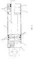
- a jack (figures 1 and 2) is constituted by a bottom 1, a liner or tube 4, a piston 2, a rod 3 and a head 5.
- the bottom 1 and the head 5 must be fastened in an irremovable way to the liner 4: the first one operating as closing member of the cylinder or the jack itself, the second one as member allowing the sliding of the rod 3 pushed by the used liquid or gas.
- the rod 3 in turn, is obviously integral with the piston 2.
- the latter which is free to slide inside the liner or tube 4, is hydraulically or pneumatically sealed with one or more preferably ring-like (O-ring) gaskets G inserted in specific grooves 6 arranged on the piston 2 itself.
- O-ring ring-like
- gaskets G and grooves 6 are utilized to guarantee the seal between the rod 3 and the head 5, as well as for the seal between bottom 1 and liner 4 and between head 5 and liner 4.
- both techniques can be used both to fasten the bottom to the tube and the head to the tube, or more frequently the welding for anchoring the bottom to the tube and the threading for anchoring the head to the tube.
- the welding procedure in particular, apart from the time required for the implementation thereof, causes a stress to the tube 4 and deforms it, by reducing the average life time of the cylinder or the jack itself.
- the rolling procedure according to the invention is performed by means of the above-mentioned mechanical rolling machine equipped with a special shaping multiroller head which, by properly acting on the tube, implements in an uniform, reproducible way and without crackings, a predetermined plastic deformation allowing the perfect mechanical seal in the coupling between tube 4 and bottom 1 and between tube 4 and head 5.
- the bottom and the head are equipped with at least a respective outer annular groove 7 wherein the deformed area of the tube 4 fits.
- the innermost groove 6 of the bottom 1 and that of the head 5 act as seat for the gasket G of appropriate material which guarantees the hydraulic or pneumatic seal, whereas the respective outer grooves 7 are apt to receive the material of the tube 4 which is "shifted" by plastic deformation with the mechanical rolling processing which is described.
- Said plastic deformation of the tube or liner 4 forms an outer annular groove and a corresponding inner ring projecting in radial direction towards the axis of the tube itself, which ring, indeed, is apt to insert into a corresponding annular groove 7 arranged both on the bottom 1 and on the head 5.
- the utilized mechanical processing guarantees a uniform contact, inside the grooves 7, between the tube 4 and the components (bottom 1 and head 5) fastened at the ends thereof.
- the mechanical rolling procedures are performed by anchoring the preassembled cylinder to the special shaping multiroller head TM implementing the closing procedure.
- the procedure can take place in cold and/or hot status, with variable pressures in a very wide range and with likewise very variable revolution speeds of the shaping rollers R1: said several parameters, upon setting up the production, have to be fastened according to sizes and thicknesses of the tube 4, features of the constituting material, etc.
- the time for performing each rolling procedure varies from few seconds to a maximum of 50-60 seconds.
- the process which is described advantageously allows to securely anchor the bottom 1 and the head 5 to the tube 4 by reducing the production waste from values higher than 70% to values lower than 0,1%.
- the average life of the product obtained according to the invention is longer than that of the currently known cylinders and jacks, since with the process sofar described the liner 4 is not subjected to deformations on allowances with the other components since no welding procedure has been performed.
- the "rolling" process sofar described is performed as follows: a special shaping multiroller head TM of a rolling machine is positioned at the area of the tube or liner 4 wherein the plastic deformation must occur which generates the outer annular groove 7 thereto an inner annular jut of the liner itself corresponds, which radially projects towards the axis of the tube 4.
- the shaping rollers R1 are approached in an uniform and gradual way to the tube 4, along a radial direction.
- the rollers R1 symmetrically move in radial direction with respect to the cylinder and also have the same simultaneous rotating motion. In this way, once in contact with the tube 4 which is free to rotate about its own axis integrally with the bottom 1 and/or the head 5 positioned inside thereof, the rolling machine causes to the same, by means of an adequate pressure of the shaping rollers R1, a localized and predetermined annular plastic deformation (in cold or hot status).
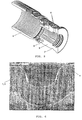
- FIG. 5 shows an exploded view wherein the deformation subjected by the tube 4 at the head 5 is clearly seen.
- the multiroller head TM preferably provides three shaping rollers R1 placed at 120° to make the apparatus self-centering, which guarantee an absolutely uniform and symmetrical distribution of loads and stresses, by reducing to the minimum the deformations and inner tensions which could create asymmetry and/or cracks.
- rollers lower or higher than three can also be used.
- a variant not comprised in the present invention shown in figure 4 provides replacing the multiroller head TM by a shaping-ring matrix M1.
- the plastic deformation is performed by a shaping ring constituted by two half-rings (matrixes) M1, shaped on the inside, which gradually approach, by rotating at predetermined speed, to the tube 4 of the cylinder, by implementing the wished plastic deformation.
- An additional variant of the head which performs the plastic deformation according to the invention, as alternative to the shaping rollers (R1), provides a single shaping roller (R1) and one or more thrust rollers to counterbalance the stresses generated by the plastic deformation.
Landscapes
- Engineering & Computer Science (AREA)
- Mechanical Engineering (AREA)
- General Engineering & Computer Science (AREA)
- Physics & Mathematics (AREA)
- Fluid Mechanics (AREA)
- Chemical & Material Sciences (AREA)
- Combustion & Propulsion (AREA)
- Pistons, Piston Rings, And Cylinders (AREA)
- Actuator (AREA)
- Placing Or Removing Of Piles Or Sheet Piles, Or Accessories Thereof (AREA)
- Road Repair (AREA)
- Lubricants (AREA)
- Shaping Metal By Deep-Drawing, Or The Like (AREA)
- Air Transport Of Granular Materials (AREA)
- Valve Device For Special Equipments (AREA)
- Fluid-Pressure Circuits (AREA)
- Shaping Of Tube Ends By Bending Or Straightening (AREA)
- Rolls And Other Rotary Bodies (AREA)
Claims (10)
- Verfahren zum Herstellen einer Hubvorrichtung oder hydraulischen, pneumatischen und/oder oleopneumatischen Zylinders von der Art umfassend einen zylindrischen rohrförmigen Körper (4), an dessen Enden ein Boden (1) und ein Kopf (5) befestigt sind, in dessen Inneren ein mit einer Stange (3) einstückig ausgebildeter Kolben (2) gleitet, dadurch gekennzeichnet, dass zur nicht entfernbaren Befestigung des Kopfes (5) und des Bodens (1) an dem rohrförmigen Körper (4) der Hubvorrichtung ohne Gewindeschneid- und/oder Schweißverfahren eine kontrollierte plastische Verformung an den Enden des rohrförmigen Körpers (4) vorgesehen wird, die sich über die gesamte Dicke des rohrförmigen Körpers selbst erstreckt, die ausgestaltet ist, die Enden desselben lokal zu verformen, indem an jedem von ihnen mindestens ein Umfangsring erzeugt wird, der radial nach innen ragt, um in mindestens eine bestimmte Nut (7) einzugreifen, die jeweils am Boden (1) sowie am Kopf (5), die selbst in das Rohr eingesetzt sind, angeordnet ist, um diese an Ort und Stelle miteinander zu verriegeln, wobei die plastische Verformung die mechanische Abdichtung der Verbindung zwischen dem rohrförmigen Körper (4) und dem Boden (1) sowie zwischen dem rohrförmigen Körper (4) und dem Kopf (5) sicherstellt, wobei die kontrollierte plastische Verformung des rohrförmigen Körpers mittels Drehwalzen durchgeführt wird, welche den rohrförmigen Körper (4) und den darin eingesetzten Kopf (5) und Boden (1) drehend antreiben,
- Verfahren nach Anspruch 1, dadurch gekennzeichnet, dass zur Sicherstellung der Abdichtung des Bodens (1), des Kopfes (5), des Kolbens (2) und der Stange (3) Dichtungen (G) in bestimmten Nuten (6) platziert werden, die an den äußeren zylindrischen Flächen des Bodens, des Kolbens sowie an den äußeren und inneren Flächen des Kopfes, in welchem die Stange gleitet, angeordnet sind.
- Verfahren nach Anspruch 1, dadurch gekennzeichnet, dass die plastische Verformung des rohrförmigen Körpers (4) geeignet ist, die gesamte Dicke des Rohres selbst zu involvieren, indem eine äußere Ringnut sowie ein entsprechender innerer Ring, der in Radialrichtung zur Achse des Rohres selbst ragt, erzeugt werden, wobei der Ring in eine sowohl am Boden (1) als auch am Kopf (5) angeordnete entsprechende Ringnut (7) eingreift.
- Verfahren nach Anspruch 1, dadurch gekennzeichnet, dass es die Durchführung der mechanischen Walzverfahren vorsieht, indem der vormontierte Zylinder oder Hubvorrichtung in mindestens einem speziellen Multiwalzenkopf (TM) mit einer oder mehreren Formwalzen (R1) verankert wird, der das Schließverfahren des Zylinders durchführt, wobei die plastische Verformung in kaltem oder warmem Zustand, mit variablen Drücken und Umdrehungsgeschwindigkeiten der Formwalzen (R1) stattfinden kann
- Verfahren nach dem vorstehenden Anspruch, dadurch gekennzeichnet, dass es vorsieht, dass die Walzen (R1) sich symmetrisch in Radialrichtung bezogen auf den Zylinder (4) bewegen und die gleiche gleichzeitige Rotationsbewegung aufweisen, wodurch erreicht wird, dass, sobald ein Kontakt mit dem rohrförmigen Körper (4) vorliegt, der sich frei um seine eigene Achse einstückig mit dem Boden (1) und/oder dem Kopf (5), die in dessen Innerem befindlich sind, bewegen kann, der Multiwalzenkopf (TM) den Zylinder selbst einer ringförmigen plastischen Verformung unterwirft, die mittels eines entsprechenden Druckes der Walzrollen (R1) lokalisiert und bestimmt wird.
- Verfahren nach einem der vorstehenden Ansprüche, dadurch gekennzeichnet, dass es im Wesentlichen die folgenden Schritte umfasst:A. Anordnen geeigneter Dichtungen (G) innerhalb entsprechender Ringnuten (6), die im Boden (1) vorgesehen sind;B. Einsetzen des Bodens (1) in eine vorbestimmte Position an einem ersten Ende des rohrförmigen Körpers (4) der Hubvorrichtung;C. Positionieren eines speziellen Multiwalzenkopfes (TM) umfassend eine oder mehrere Formwalzen (R1) am ersten Ende des rohrförmigen Körpers (4);D. gleichzeitiges Annähern der Formwalzen (R1) an die äußere zylindrische Fläche des rohrförmigen Körpers (4) und Durchführen einer plastischen Verformung durch Walzen;E. Entfernen der Formwalzen (R1) von dem Zylinder;F. Anordnen der Dichtungen (G) in den entsprechenden Ringnuten (6), die im mit der Stange einstückig ausgeführten Kolben (2) vorgesehen sind;G. Anordnen zusätzlicher Dichtungen (G) in den entsprechenden Ringnuten (6), die an der äußeren und inneren zylindrischen Fläche des Kopfes (5) vorgesehen sind;H. Einsetzen des Kolbens (2) innerhalb des rohrförmigen Körpers (4) sowie des bereits auf die Stange gesetzten Kopfes (5) in eine vorbestimmte Position desselben an einem zweiten Ende des rohrförmigen Körpers (4) der Hubvorrichtung;I. Positionieren eines speziellen Multiwalzenkopfes (TM) mit einer oder mehreren Formwalzen (R1) am oben genannten Ende des Rohres (4);J. gleichzeitiges Annähern der Formwalzen (R1) an die äußere zylindrische Fläche des rohrförmigen Körpers (4) und Durchführen einer plastischen Verformung durch Walzen;K. Entfernen der Formwalzen (R1) von dem Zylinder;
- Verfahren nach dem vorstehenden Anspruch, dadurch gekennzeichnet, dass im Falle des Vorliegens von zwei Multiwalzenköpfen (TM) die Schritte A, B, F-H zuerst ausgeführt werden, während die folgenden Schritte C-E, I-K gleichzeitig ausgeführt werden
- Vorrichtung zum Herstellen einer Hubvorrichtung oder hydraulischen, pneumatischen und/oder oleopneumatischen Zylinders mittels des Verfahrens nach den vorstehenden Ansprüchen, umfassend einen Multiwalzenkopf (TM), der mindestens zwei gegenüberliegende Drehformwalzen (R1) aufweist, die sich der Fläche des rohrförmigen Körpers (4) auf gleichzeitige und symmetrische Weise nähern, wobei die Drehwalzen (R1) ausgestaltet sind, den rohrförmigen Körper (4) sowie den darin eingesetzten Kopf (1) und Boden (5) drehend anzutreiben, die sich frei um ihre eigene Achse drehen können.
- Vorrichtung zum Herstellen einer Hubvorrichtung oder hydraulischen, pneumatischen und/oder oleopneumatischen Zylinders mittels des Verfahrens nach den Ansprüchen 1 bis 7, umfassend eine einzelne Formwalze (R1) und eine oder mehrere Axialrollen zum Ausgleichen der durch die plastische Verformung erzeugten Spannungen, die sich der Fläche des rohrförmigen Körpers (4) auf gleichzeitige und symmetrische Weise nähern, wobei die einzelne Walze (R1) ausgestaltet ist, den rohrförmigen Körper (4) sowie den darin eingesetzten Kopf (1) und Boden (5) drehend anzutreiben, die sich frei um ihre eigene Achse drehen können.
- Vorrichtung nach Anspruch 8, dadurch gekennzeichnet, dass drei Drehformwalzen (R1) vorgesehen sind, die bei 120° angeordnet sind, um eine Selbstzentrierung der Vorrichtung zu ermöglichen, wodurch eine absolut einheitliche und symmetrische Verteilung der Belastungen und Beanspruchungen sichergestellt wird, indem die inneren Verformungen und Spannungen, die Asymmetrien und/oder Brüche verursachen könnten, auf das Minimum reduziert werden
Applications Claiming Priority (3)
| Application Number | Priority Date | Filing Date | Title |
|---|---|---|---|
| IT2002RM000268A ITRM20020268A1 (it) | 2002-05-15 | 2002-05-15 | Metodo per la chiusura di un cilindro idraulico, pneumatico e/o oleopneumatico, e mezzi per la sua attuazione. |
| ITRM20020268 | 2002-05-15 | ||
| PCT/IT2003/000255 WO2003097269A1 (en) | 2002-05-15 | 2003-04-23 | Method for closing a hydraulic pneumatic and/or oleopneumatic cylinder and means for implementing thereof |
Publications (2)
| Publication Number | Publication Date |
|---|---|
| EP1534446A1 EP1534446A1 (de) | 2005-06-01 |
| EP1534446B1 true EP1534446B1 (de) | 2007-07-18 |
Family
ID=11456303
Family Applications (1)
| Application Number | Title | Priority Date | Filing Date |
|---|---|---|---|
| EP03723079A Expired - Lifetime EP1534446B1 (de) | 2002-05-15 | 2003-04-23 | Verfahren zum verschliessen eines hydraulischen, pneumatischen und/oder hydropneumatischen zylinders sowie vorrichtung zur durchführung des verfahrens |
Country Status (17)
| Country | Link |
|---|---|
| US (1) | US7614133B2 (de) |
| EP (1) | EP1534446B1 (de) |
| JP (1) | JP2005525521A (de) |
| KR (1) | KR20050067108A (de) |
| CN (1) | CN100366360C (de) |
| AT (1) | ATE367224T1 (de) |
| AU (1) | AU2003230222B2 (de) |
| BR (1) | BR0310107B1 (de) |
| CA (1) | CA2498954C (de) |
| DE (1) | DE60315038T2 (de) |
| EA (1) | EA007192B1 (de) |
| ES (1) | ES2291633T3 (de) |
| IT (1) | ITRM20020268A1 (de) |
| NO (1) | NO20045472L (de) |
| PL (1) | PL205335B1 (de) |
| WO (1) | WO2003097269A1 (de) |
| ZA (1) | ZA200408918B (de) |
Families Citing this family (12)
| Publication number | Priority date | Publication date | Assignee | Title |
|---|---|---|---|---|
| GB2414043A (en) * | 2004-05-14 | 2005-11-16 | Parker Hannifin Plc | Actuator with crimped on end members |
| JP5403220B2 (ja) * | 2009-01-30 | 2014-01-29 | 日立オートモティブシステムズ株式会社 | シリンダ装置及びシリンダ装置の製造方法 |
| NO337662B1 (no) * | 2011-01-31 | 2016-05-30 | Modular Cylinder System As | Hydraulisk sylinder og fremgangsmåte for dens fremstilling |
| US9194409B2 (en) | 2012-01-09 | 2015-11-24 | Thomas & Betts International, Inc. | Disconnect device |
| DE102013217841B4 (de) * | 2013-09-06 | 2021-05-20 | Aventics Gmbh | Zylinder, aufweisend ein Zylinderrohr und ein Abschlusselement und Verfahren zum Herstellen eines Zylinders |
| JP6647551B2 (ja) * | 2015-10-14 | 2020-02-14 | Smc株式会社 | 流体圧機器及びその製造方法 |
| ITUA20164077A1 (it) * | 2016-06-03 | 2017-12-03 | Ognibene Power Spa | Metodo di assemblaggio di un gruppo cilindro-pistone e gruppo cilindro-pistone cosi’ ottenuto |
| US20180297102A1 (en) * | 2017-04-12 | 2018-10-18 | Xilix Systems LLC | Systems and methods for deforming a tube within a cap |
| CN108672571A (zh) * | 2018-05-21 | 2018-10-19 | 晋西工业集团有限责任公司 | 一种辊压成型工艺 |
| JP7110998B2 (ja) * | 2019-01-16 | 2022-08-02 | 豊田合成株式会社 | アクチュエータ |
| CN112112859A (zh) * | 2019-06-19 | 2020-12-22 | 蔡跃波 | 液压油缸 |
| US11131330B1 (en) * | 2020-03-30 | 2021-09-28 | Caterpillar Inc. | Crimp retained hydraulic cylinder head and cap |
Family Cites Families (12)
| Publication number | Priority date | Publication date | Assignee | Title |
|---|---|---|---|---|
| US2000680A (en) * | 1931-12-18 | 1935-05-07 | Weatherhead Co | Hose coupling |
| US2487512A (en) * | 1946-01-10 | 1949-11-08 | Automotive & Aircraft Hydrauli | Cylinder and cylinder head construction |
| US2957734A (en) * | 1956-10-02 | 1960-10-25 | Dura Corp | Hydraulic cylinder |
| US3068563A (en) * | 1958-11-05 | 1962-12-18 | Westinghouse Electric Corp | Metal joining method |
| US3811367A (en) * | 1972-05-01 | 1974-05-21 | C Bimba | Fluid power cylinder construction |
| US4791712A (en) * | 1986-09-02 | 1988-12-20 | General Motors Corporation | Modular piston with high strength tensile joint and method of manufacture |
| JPH0272832U (de) * | 1988-11-21 | 1990-06-04 | ||
| JP2788653B2 (ja) * | 1989-09-01 | 1998-08-20 | 太陽鉄工株式会社 | 流体圧シリンダのカバー取付け装置 |
| JP2541455Y2 (ja) * | 1990-08-21 | 1997-07-16 | カヤバ工業株式会社 | 油圧シリンダ |
| JPH10238640A (ja) * | 1997-02-28 | 1998-09-08 | Sanpo Shindo Kogyo Kk | パイプ型逆止弁 |
| JP2001105062A (ja) * | 1999-10-01 | 2001-04-17 | Saginomiya Seisakusho Inc | かしめ結合工具およびかしめ結合方法 |
| DE50001805D1 (de) * | 2000-09-04 | 2003-05-22 | Knipping Daniel | Vorrichtung zur Herstellung einer unlösbaren Verbindung zwischen dem Endbereich eines Rohres und einem Verbindungselement |
-
2002
- 2002-05-15 IT IT2002RM000268A patent/ITRM20020268A1/it unknown
-
2003
- 2003-04-23 AT AT03723079T patent/ATE367224T1/de not_active IP Right Cessation
- 2003-04-23 WO PCT/IT2003/000255 patent/WO2003097269A1/en not_active Ceased
- 2003-04-23 CA CA2498954A patent/CA2498954C/en not_active Expired - Fee Related
- 2003-04-23 JP JP2004504652A patent/JP2005525521A/ja active Pending
- 2003-04-23 PL PL372582A patent/PL205335B1/pl not_active IP Right Cessation
- 2003-04-23 US US10/514,319 patent/US7614133B2/en not_active Expired - Fee Related
- 2003-04-23 EP EP03723079A patent/EP1534446B1/de not_active Expired - Lifetime
- 2003-04-23 CN CNB038108216A patent/CN100366360C/zh not_active Expired - Fee Related
- 2003-04-23 AU AU2003230222A patent/AU2003230222B2/en not_active Expired - Fee Related
- 2003-04-23 BR BRPI0310107-0A patent/BR0310107B1/pt not_active IP Right Cessation
- 2003-04-23 DE DE60315038T patent/DE60315038T2/de not_active Expired - Lifetime
- 2003-04-23 ES ES03723079T patent/ES2291633T3/es not_active Expired - Lifetime
- 2003-04-23 KR KR1020047018304A patent/KR20050067108A/ko not_active Withdrawn
- 2003-04-23 EA EA200401499A patent/EA007192B1/ru not_active IP Right Cessation
-
2004
- 2004-11-04 ZA ZA200408918A patent/ZA200408918B/en unknown
- 2004-12-15 NO NO20045472A patent/NO20045472L/no not_active Application Discontinuation
Also Published As
| Publication number | Publication date |
|---|---|
| AU2003230222A2 (en) | 2003-12-02 |
| PL205335B1 (pl) | 2010-04-30 |
| CN100366360C (zh) | 2008-02-06 |
| BR0310107A (pt) | 2005-03-01 |
| ITRM20020268A0 (it) | 2002-05-15 |
| EA007192B1 (ru) | 2006-08-25 |
| ATE367224T1 (de) | 2007-08-15 |
| BR0310107B1 (pt) | 2011-10-04 |
| WO2003097269A1 (en) | 2003-11-27 |
| ES2291633T3 (es) | 2008-03-01 |
| DE60315038T2 (de) | 2008-04-10 |
| ZA200408918B (en) | 2006-05-31 |
| ITRM20020268A1 (it) | 2003-11-17 |
| US20060075622A1 (en) | 2006-04-13 |
| PL372582A1 (en) | 2005-07-25 |
| DE60315038D1 (de) | 2007-08-30 |
| CN1652883A (zh) | 2005-08-10 |
| JP2005525521A (ja) | 2005-08-25 |
| AU2003230222A1 (en) | 2003-12-02 |
| EA200401499A1 (ru) | 2005-10-27 |
| NO20045472L (no) | 2004-12-15 |
| US7614133B2 (en) | 2009-11-10 |
| CA2498954A1 (en) | 2003-11-27 |
| KR20050067108A (ko) | 2005-06-30 |
| CA2498954C (en) | 2011-07-12 |
| EP1534446A1 (de) | 2005-06-01 |
| AU2003230222B2 (en) | 2007-07-12 |
Similar Documents
| Publication | Publication Date | Title |
|---|---|---|
| EP1534446B1 (de) | Verfahren zum verschliessen eines hydraulischen, pneumatischen und/oder hydropneumatischen zylinders sowie vorrichtung zur durchführung des verfahrens | |
| USRE30802E (en) | Method of securing a sleeve within a tube | |
| US4107249A (en) | Method for forming an annular groove in a thermoplastic pipe | |
| US6170888B1 (en) | Conduit connector and method | |
| US3172928A (en) | Method for deep forming fluorocarbon polymer sheet material | |
| CN103418674B (zh) | 钛合金矩形截面环形件热胀形成异形截面环形件的方法 | |
| US20020056305A1 (en) | High-pressure bulge-forming apparatus | |
| US3949045A (en) | Extruded pipe coupling and method and apparatus for forming | |
| CN103447377B (zh) | 不锈钢矩形截面环形件的热胀形成形方法 | |
| WO2004033143A1 (en) | Method to make mechanical components for fluid-dynamic devices, compressors or motors operating at high pressure, and mechanical components thus achieved | |
| US3194041A (en) | Method for forming corrugated tubes | |
| CN103433362B (zh) | 不锈钢矩形截面环形件热胀形成异形截面环形件的方法 | |
| US3146286A (en) | Method for making lined valves | |
| CN103447378B (zh) | 轴承钢矩形截面环形件的热胀形成形方法 | |
| CN103433365A (zh) | 轴承钢矩形截面环形件热胀形成异形截面环形件的方法 | |
| US6089064A (en) | Sliding plug for applying end loads during isostatic bulge forming | |
| US3140535A (en) | Autofrettage method and apparatus | |
| KR101700710B1 (ko) | 피스톤 실링 조립체 제조방법 | |
| CN222001461U (zh) | 一种用于制造胀形贮箱箱底的封头工装 | |
| EP1363060A2 (de) | Rohrkupplung und Verfahren | |
| CN216681968U (zh) | 一种油缸密封件更换工装 | |
| CN103433363B (zh) | 高温合金矩形截面环形件热胀形成异形截面环形件的方法 | |
| SU985523A1 (ru) | Способ креплени пластмассового уплотнител | |
| SU1318319A1 (ru) | Способ правки кольцевых изделий | |
| CN105312471A (zh) | 异形环件坯料镦挤成型的模具 |
Legal Events
| Date | Code | Title | Description |
|---|---|---|---|
| PUAI | Public reference made under article 153(3) epc to a published international application that has entered the european phase |
Free format text: ORIGINAL CODE: 0009012 |
|
| 17P | Request for examination filed |
Effective date: 20050321 |
|
| AK | Designated contracting states |
Kind code of ref document: A1 Designated state(s): AT BE BG CH CY CZ DE DK EE ES FI FR GB GR HU IE IT LI LU MC NL PT RO SE SI SK TR |
|
| AX | Request for extension of the european patent |
Extension state: AL LT LV MK |
|
| GRAP | Despatch of communication of intention to grant a patent |
Free format text: ORIGINAL CODE: EPIDOSNIGR1 |
|
| GRAS | Grant fee paid |
Free format text: ORIGINAL CODE: EPIDOSNIGR3 |
|
| GRAA | (expected) grant |
Free format text: ORIGINAL CODE: 0009210 |
|
| AK | Designated contracting states |
Kind code of ref document: B1 Designated state(s): AT BE BG CH CY CZ DE DK EE ES FI FR GB GR HU IE IT LI LU MC NL PT RO SE SI SK TR |
|
| AX | Request for extension of the european patent |
Extension state: AL LT LV MK |
|
| RAP1 | Party data changed (applicant data changed or rights of an application transferred) |
Owner name: KARBOREK SRL Owner name: ENEA-ENTE PER LE NUOVE TECNOLOGIE, L'ENERGIA E L'A |
|
| REG | Reference to a national code |
Ref country code: GB Ref legal event code: FG4D |
|
| REG | Reference to a national code |
Ref country code: CH Ref legal event code: EP |
|
| REF | Corresponds to: |
Ref document number: 60315038 Country of ref document: DE Date of ref document: 20070830 Kind code of ref document: P |
|
| REG | Reference to a national code |
Ref country code: IE Ref legal event code: FG4D |
|
| REG | Reference to a national code |
Ref country code: RO Ref legal event code: EPE |
|
| REG | Reference to a national code |
Ref country code: SE Ref legal event code: TRGR |
|
| REG | Reference to a national code |
Ref country code: CH Ref legal event code: NV Representative=s name: PATENTS & TECHNOLOGY SURVEYS SA |
|
| LTIE | Lt: invalidation of european patent or patent extension |
Effective date: 20070718 |
|
| PG25 | Lapsed in a contracting state [announced via postgrant information from national office to epo] |
Ref country code: BG Free format text: LAPSE BECAUSE OF FAILURE TO SUBMIT A TRANSLATION OF THE DESCRIPTION OR TO PAY THE FEE WITHIN THE PRESCRIBED TIME-LIMIT Effective date: 20071018 Ref country code: PT Free format text: LAPSE BECAUSE OF FAILURE TO SUBMIT A TRANSLATION OF THE DESCRIPTION OR TO PAY THE FEE WITHIN THE PRESCRIBED TIME-LIMIT Effective date: 20071218 |
|
| PG25 | Lapsed in a contracting state [announced via postgrant information from national office to epo] |
Ref country code: AT Free format text: LAPSE BECAUSE OF FAILURE TO SUBMIT A TRANSLATION OF THE DESCRIPTION OR TO PAY THE FEE WITHIN THE PRESCRIBED TIME-LIMIT Effective date: 20070718 |
|
| REG | Reference to a national code |
Ref country code: ES Ref legal event code: FG2A Ref document number: 2291633 Country of ref document: ES Kind code of ref document: T3 |
|
| PG25 | Lapsed in a contracting state [announced via postgrant information from national office to epo] |
Ref country code: DK Free format text: LAPSE BECAUSE OF FAILURE TO SUBMIT A TRANSLATION OF THE DESCRIPTION OR TO PAY THE FEE WITHIN THE PRESCRIBED TIME-LIMIT Effective date: 20070718 Ref country code: GR Free format text: LAPSE BECAUSE OF FAILURE TO SUBMIT A TRANSLATION OF THE DESCRIPTION OR TO PAY THE FEE WITHIN THE PRESCRIBED TIME-LIMIT Effective date: 20071019 |
|
| PLBE | No opposition filed within time limit |
Free format text: ORIGINAL CODE: 0009261 |
|
| STAA | Information on the status of an ep patent application or granted ep patent |
Free format text: STATUS: NO OPPOSITION FILED WITHIN TIME LIMIT |
|
| PG25 | Lapsed in a contracting state [announced via postgrant information from national office to epo] |
Ref country code: SK Free format text: LAPSE BECAUSE OF FAILURE TO SUBMIT A TRANSLATION OF THE DESCRIPTION OR TO PAY THE FEE WITHIN THE PRESCRIBED TIME-LIMIT Effective date: 20070718 |
|
| 26N | No opposition filed |
Effective date: 20080421 |
|
| PG25 | Lapsed in a contracting state [announced via postgrant information from national office to epo] |
Ref country code: MC Free format text: LAPSE BECAUSE OF NON-PAYMENT OF DUE FEES Effective date: 20080430 |
|
| PG25 | Lapsed in a contracting state [announced via postgrant information from national office to epo] |
Ref country code: EE Free format text: LAPSE BECAUSE OF FAILURE TO SUBMIT A TRANSLATION OF THE DESCRIPTION OR TO PAY THE FEE WITHIN THE PRESCRIBED TIME-LIMIT Effective date: 20070718 |
|
| PG25 | Lapsed in a contracting state [announced via postgrant information from national office to epo] |
Ref country code: IE Free format text: LAPSE BECAUSE OF NON-PAYMENT OF DUE FEES Effective date: 20080423 |
|
| PG25 | Lapsed in a contracting state [announced via postgrant information from national office to epo] |
Ref country code: SI Free format text: LAPSE BECAUSE OF FAILURE TO SUBMIT A TRANSLATION OF THE DESCRIPTION OR TO PAY THE FEE WITHIN THE PRESCRIBED TIME-LIMIT Effective date: 20070718 |
|
| PG25 | Lapsed in a contracting state [announced via postgrant information from national office to epo] |
Ref country code: CY Free format text: LAPSE BECAUSE OF FAILURE TO SUBMIT A TRANSLATION OF THE DESCRIPTION OR TO PAY THE FEE WITHIN THE PRESCRIBED TIME-LIMIT Effective date: 20070718 |
|
| PG25 | Lapsed in a contracting state [announced via postgrant information from national office to epo] |
Ref country code: LU Free format text: LAPSE BECAUSE OF NON-PAYMENT OF DUE FEES Effective date: 20080423 Ref country code: HU Free format text: LAPSE BECAUSE OF FAILURE TO SUBMIT A TRANSLATION OF THE DESCRIPTION OR TO PAY THE FEE WITHIN THE PRESCRIBED TIME-LIMIT Effective date: 20080119 |
|
| PGFP | Annual fee paid to national office [announced via postgrant information from national office to epo] |
Ref country code: FI Payment date: 20100426 Year of fee payment: 8 |
|
| PG25 | Lapsed in a contracting state [announced via postgrant information from national office to epo] |
Ref country code: TR Free format text: LAPSE BECAUSE OF FAILURE TO SUBMIT A TRANSLATION OF THE DESCRIPTION OR TO PAY THE FEE WITHIN THE PRESCRIBED TIME-LIMIT Effective date: 20070718 |
|
| PGFP | Annual fee paid to national office [announced via postgrant information from national office to epo] |
Ref country code: CZ Payment date: 20100412 Year of fee payment: 8 Ref country code: NL Payment date: 20100421 Year of fee payment: 8 |
|
| PGFP | Annual fee paid to national office [announced via postgrant information from national office to epo] |
Ref country code: CH Payment date: 20100517 Year of fee payment: 8 |
|
| PGFP | Annual fee paid to national office [announced via postgrant information from national office to epo] |
Ref country code: GB Payment date: 20100428 Year of fee payment: 8 Ref country code: SE Payment date: 20100423 Year of fee payment: 8 |
|
| REG | Reference to a national code |
Ref country code: CH Ref legal event code: PFA Owner name: ENEA-ENTE PER LE NUOVE TECNOLOGIE, L'ENERGIA E L' Free format text: ENEA-ENTE PER LE NUOVE TECNOLOGIE, L'ENERGIA E L'AMBIENTE#LUNGOTEVERE GRANDE AMMIRAGLIO THAON DI REVEL, 76#00196 ROME (IT) $ KARBOREK SRL#VIA ROMA, 134#73020 MARTIGNANO (LE) (IT) -TRANSFER TO- ENEA-ENTE PER LE NUOVE TECNOLOGIE, L'ENERGIA E L'AMBIENTE#LUNGOTEVERE GRANDE AMMIRAGLIO THAON DI REVEL, 76#00196 ROME (IT) $ KARBOREK SRL#VIA ROMA, 134#73020 MARTIGNANO (LE) (IT) |
|
| PGFP | Annual fee paid to national office [announced via postgrant information from national office to epo] |
Ref country code: RO Payment date: 20100423 Year of fee payment: 8 |
|
| REG | Reference to a national code |
Ref country code: NL Ref legal event code: V1 Effective date: 20111101 |
|
| REG | Reference to a national code |
Ref country code: SE Ref legal event code: EUG |
|
| REG | Reference to a national code |
Ref country code: CH Ref legal event code: PL |
|
| GBPC | Gb: european patent ceased through non-payment of renewal fee |
Effective date: 20110423 |
|
| PG25 | Lapsed in a contracting state [announced via postgrant information from national office to epo] |
Ref country code: CH Free format text: LAPSE BECAUSE OF NON-PAYMENT OF DUE FEES Effective date: 20110430 Ref country code: FI Free format text: LAPSE BECAUSE OF NON-PAYMENT OF DUE FEES Effective date: 20110423 Ref country code: CZ Free format text: LAPSE BECAUSE OF NON-PAYMENT OF DUE FEES Effective date: 20110423 Ref country code: NL Free format text: LAPSE BECAUSE OF NON-PAYMENT OF DUE FEES Effective date: 20111101 Ref country code: LI Free format text: LAPSE BECAUSE OF NON-PAYMENT OF DUE FEES Effective date: 20110430 |
|
| PG25 | Lapsed in a contracting state [announced via postgrant information from national office to epo] |
Ref country code: GB Free format text: LAPSE BECAUSE OF NON-PAYMENT OF DUE FEES Effective date: 20110423 |
|
| PGFP | Annual fee paid to national office [announced via postgrant information from national office to epo] |
Ref country code: DE Payment date: 20120614 Year of fee payment: 10 |
|
| PGFP | Annual fee paid to national office [announced via postgrant information from national office to epo] |
Ref country code: BE Payment date: 20121030 Year of fee payment: 10 Ref country code: FR Payment date: 20121128 Year of fee payment: 10 |
|
| PGFP | Annual fee paid to national office [announced via postgrant information from national office to epo] |
Ref country code: ES Payment date: 20121129 Year of fee payment: 10 Ref country code: IT Payment date: 20121030 Year of fee payment: 10 |
|
| PG25 | Lapsed in a contracting state [announced via postgrant information from national office to epo] |
Ref country code: SE Free format text: LAPSE BECAUSE OF NON-PAYMENT OF DUE FEES Effective date: 20110424 Ref country code: RO Free format text: LAPSE BECAUSE OF NON-PAYMENT OF DUE FEES Effective date: 20120423 |
|
| BERE | Be: lapsed |
Owner name: KARBOREK SRL Effective date: 20130430 Owner name: ENEA-ENTE PER LE NUOVE TECNOLOGIE, L'ENERGIA E L' Effective date: 20130430 |
|
| PG25 | Lapsed in a contracting state [announced via postgrant information from national office to epo] |
Ref country code: DE Free format text: LAPSE BECAUSE OF NON-PAYMENT OF DUE FEES Effective date: 20131101 Ref country code: BE Free format text: LAPSE BECAUSE OF NON-PAYMENT OF DUE FEES Effective date: 20130430 |
|
| REG | Reference to a national code |
Ref country code: FR Ref legal event code: ST Effective date: 20131231 |
|
| REG | Reference to a national code |
Ref country code: DE Ref legal event code: R119 Ref document number: 60315038 Country of ref document: DE Effective date: 20131101 |
|
| PG25 | Lapsed in a contracting state [announced via postgrant information from national office to epo] |
Ref country code: FR Free format text: LAPSE BECAUSE OF NON-PAYMENT OF DUE FEES Effective date: 20130430 Ref country code: IT Free format text: LAPSE BECAUSE OF NON-PAYMENT OF DUE FEES Effective date: 20130423 |
|
| REG | Reference to a national code |
Ref country code: ES Ref legal event code: FD2A Effective date: 20140611 |
|
| PG25 | Lapsed in a contracting state [announced via postgrant information from national office to epo] |
Ref country code: ES Free format text: LAPSE BECAUSE OF NON-PAYMENT OF DUE FEES Effective date: 20130424 |