EP1533914B1 - Drahtloses Kommunicationsgerät und zugehörige Verarbeitungsmethode für Antwortdaten - Google Patents
Drahtloses Kommunicationsgerät und zugehörige Verarbeitungsmethode für Antwortdaten Download PDFInfo
- Publication number
- EP1533914B1 EP1533914B1 EP04027332.8A EP04027332A EP1533914B1 EP 1533914 B1 EP1533914 B1 EP 1533914B1 EP 04027332 A EP04027332 A EP 04027332A EP 1533914 B1 EP1533914 B1 EP 1533914B1
- Authority
- EP
- European Patent Office
- Prior art keywords
- wireless communication
- response
- response data
- unit
- data
- Prior art date
- Legal status (The legal status is an assumption and is not a legal conclusion. Google has not performed a legal analysis and makes no representation as to the accuracy of the status listed.)
- Expired - Lifetime
Links
Images


Classifications
-
- H—ELECTRICITY
- H04—ELECTRIC COMMUNICATION TECHNIQUE
- H04B—TRANSMISSION
- H04B5/00—Near-field transmission systems, e.g. inductive or capacitive transmission systems
- H04B5/40—Near-field transmission systems, e.g. inductive or capacitive transmission systems characterised by components specially adapted for near-field transmission
- H04B5/48—Transceivers
-
- G—PHYSICS
- G06—COMPUTING OR CALCULATING; COUNTING
- G06K—GRAPHICAL DATA READING; PRESENTATION OF DATA; RECORD CARRIERS; HANDLING RECORD CARRIERS
- G06K7/00—Methods or arrangements for sensing record carriers, e.g. for reading patterns
- G06K7/0008—General problems related to the reading of electronic memory record carriers, independent of its reading method, e.g. power transfer
-
- G—PHYSICS
- G06—COMPUTING OR CALCULATING; COUNTING
- G06K—GRAPHICAL DATA READING; PRESENTATION OF DATA; RECORD CARRIERS; HANDLING RECORD CARRIERS
- G06K7/00—Methods or arrangements for sensing record carriers, e.g. for reading patterns
- G06K7/10—Methods or arrangements for sensing record carriers, e.g. for reading patterns by electromagnetic radiation, e.g. optical sensing; by corpuscular radiation
- G06K7/10009—Methods or arrangements for sensing record carriers, e.g. for reading patterns by electromagnetic radiation, e.g. optical sensing; by corpuscular radiation sensing by radiation using wavelengths larger than 0.1 mm, e.g. radio-waves or microwaves
- G06K7/10019—Methods or arrangements for sensing record carriers, e.g. for reading patterns by electromagnetic radiation, e.g. optical sensing; by corpuscular radiation sensing by radiation using wavelengths larger than 0.1 mm, e.g. radio-waves or microwaves resolving collision on the communication channels between simultaneously or concurrently interrogated record carriers.
- G06K7/10029—Methods or arrangements for sensing record carriers, e.g. for reading patterns by electromagnetic radiation, e.g. optical sensing; by corpuscular radiation sensing by radiation using wavelengths larger than 0.1 mm, e.g. radio-waves or microwaves resolving collision on the communication channels between simultaneously or concurrently interrogated record carriers. the collision being resolved in the time domain, e.g. using binary tree search or RFID responses allocated to a random time slot
- G06K7/10039—Methods or arrangements for sensing record carriers, e.g. for reading patterns by electromagnetic radiation, e.g. optical sensing; by corpuscular radiation sensing by radiation using wavelengths larger than 0.1 mm, e.g. radio-waves or microwaves resolving collision on the communication channels between simultaneously or concurrently interrogated record carriers. the collision being resolved in the time domain, e.g. using binary tree search or RFID responses allocated to a random time slot interrogator driven, i.e. synchronous
-
- G—PHYSICS
- G06—COMPUTING OR CALCULATING; COUNTING
- G06Q—INFORMATION AND COMMUNICATION TECHNOLOGY [ICT] SPECIALLY ADAPTED FOR ADMINISTRATIVE, COMMERCIAL, FINANCIAL, MANAGERIAL OR SUPERVISORY PURPOSES; SYSTEMS OR METHODS SPECIALLY ADAPTED FOR ADMINISTRATIVE, COMMERCIAL, FINANCIAL, MANAGERIAL OR SUPERVISORY PURPOSES, NOT OTHERWISE PROVIDED FOR
- G06Q20/00—Payment architectures, schemes or protocols
- G06Q20/30—Payment architectures, schemes or protocols characterised by the use of specific devices or networks
- G06Q20/34—Payment architectures, schemes or protocols characterised by the use of specific devices or networks using cards, e.g. integrated circuit [IC] cards or magnetic cards
- G06Q20/341—Active cards, i.e. cards including their own processing means, e.g. including an IC or chip
-
- G—PHYSICS
- G07—CHECKING-DEVICES
- G07F—COIN-FREED OR LIKE APPARATUS
- G07F7/00—Mechanisms actuated by objects other than coins to free or to actuate vending, hiring, coin or paper currency dispensing or refunding apparatus
- G07F7/08—Mechanisms actuated by objects other than coins to free or to actuate vending, hiring, coin or paper currency dispensing or refunding apparatus by coded identity card or credit card or other personal identification means
- G07F7/0806—Details of the card
- G07F7/0833—Card having specific functional components
- G07F7/084—Additional components relating to data transfer and storing, e.g. error detection, self-diagnosis
-
- G—PHYSICS
- G07—CHECKING-DEVICES
- G07F—COIN-FREED OR LIKE APPARATUS
- G07F7/00—Mechanisms actuated by objects other than coins to free or to actuate vending, hiring, coin or paper currency dispensing or refunding apparatus
- G07F7/08—Mechanisms actuated by objects other than coins to free or to actuate vending, hiring, coin or paper currency dispensing or refunding apparatus by coded identity card or credit card or other personal identification means
- G07F7/10—Mechanisms actuated by objects other than coins to free or to actuate vending, hiring, coin or paper currency dispensing or refunding apparatus by coded identity card or credit card or other personal identification means together with a coded signal, e.g. in the form of personal identification information, like personal identification number [PIN] or biometric data
- G07F7/1008—Active credit-cards provided with means to personalise their use, e.g. with PIN-introduction/comparison system
Definitions
- the present invention relates to wireless communication apparatuses, and more specifically to a wireless communication apparatus incorporating near field communication (NFC) technology.
- NFC near field communication
- a compact and lightweight terminal device such as a mobile phone, incorporates a non-contact IC (integrated circuit) card and communicates with, for example, an IC card reader/writer (see, for example, Japanese Unexamined Patent Application Publication No. 2002-345037 ).
- a mobile phone incorporates a non-contact IC card and the card of the mobile phone is brought into close proximity to an IC card R/W (IC card reader/writer), thus allowing the information stored in the non-contact IC card to be communicated over electromagnetic waves from the IC card reader/writer.
- NFC near field communication
- the NFC system Due to its shorter communication range than wireless communication systems, such as Bluetooth and wireless LAN systems, the NFC system provides high security communication.
- the NFC technology has also attracted attention in view of a different feature from traditional communication technologies, namely, that the NFC technology enables automatic communication between NFC-incorporated devices within or near a predetermined region.
- the NFC technology also enables data communication at high transfer rates (e.g., up to 424 kbps), at which high-quality images can be transmitted.
- a portable wireless communication terminal such as a mobile phone or a PDA, including a wireless communication interface device incorporating NFC technology enables credit card settlement and access to network content, such as tickets and games, in a simple manner once the NFC-incorporated device is brought into close proximity.
- the NFC technology is also expected, by content and service providers, to provide a new mechanism for users to access various services.
- a wireless communication control device e.g., a wireless communication interface device
- a controller e.g., a baseband controller
- the controller When wirelessly transmitting or receiving frames, the controller must read and write the information stored in a register of the wireless communication interface device at a high rate. If the controller cannot access the register of the wireless communication interface device at high rate, communication is not established.
- a response check, such as polling, required for detecting a communicating party within a communication range is particularly time-critical because response data, such as polling responses, must be transmitted and received in a limited short period of time.
- a high-performance controller is required for performing response checking and other normal processing.
- a high-performance controller is required for performing response checking and other normal processing.
- EP 132889 discloses an IC card reader/writer protocol comprising a response-detection unit of detecting normal responses and collisions form IC cards.
- time-critical response data processing can be performed independently without control of a controller.
- the present invention is applicable to a wireless communication apparatus capable of wireless communication, particularly, to a wireless communication apparatus incorporating NFC technology.
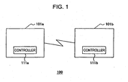
- FIG. 1 is a schematic diagram of a wireless communication system 100 including the wireless communication apparatus of this embodiment.
- the wireless communication system 100 includes a plurality of wireless communication apparatuses 101 (101a and 101b). Although two wireless communication apparatuses 101 are shown in Fig. 1 , any number of communication apparatuses more than one may be used.
- the wireless communication apparatus 101 that issues a polling command is referred to as an initiator
- the wireless communication apparatus 101 that receives a polling command from the initiator and that issues and transmits a polling response to the initiator is referred to as a target.
- the polling command may be, but is not limited to, one type of response request data for requesting response data.
- the wireless communication apparatus 101a is an initiator and the wireless communication apparatus 101b is a target.
- the target is allowed to receive a polling command issued by the initiator at predetermined time intervals.
- the initiator Upon receiving a polling response issued from the target within a time limit, the initiator identifies the target (the wireless communication apparatus 101b), and communicates with the target. Polling is described in detail below.
- the wireless communication apparatus 101 may be a communication apparatus using the NFC technology.
- the wireless communication apparatus 101 may be a battery-equipped apparatus, such as a mobile phone, a digital camera, a notebook PC, an IC card reader/writer, or a PDA, or a non-battery apparatus, such as a non-contact TIC card.
- the wireless communication apparatus 101 in the wireless communication system 100 includes a control circuit having a controller 111 for controlling the wireless
- the controller 111 (including controllers 111a and 111b) is a control unit that controls the overall apparatus, and the control unit may be, but is not limited to, for example, a baseband controller of a mobile phone, a central processing unit (CPU) of a notebook PC, or a microprocessor.
- the control unit may be, but is not limited to, for example, a baseband controller of a mobile phone, a central processing unit (CPU) of a notebook PC, or a microprocessor.
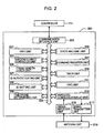
- Fig. 2 is a schematic block diagram of the wireless communication apparatus 101 according to this embodiment.
- the wireless communication apparatus 101 includes at least the controller 111, a wireless communication interface device 201, and an antenna unit 219.
- the wireless communication interface device 201 issues a polling command at predetermined time intervals and transmits the polling command in form of 13.56-MHz AM-modulated RF signals via the antenna unit 219, or receives a polling response and stores the polling response data demodulated from the RF signal.
- the wireless communication interface device 201 includes a communication interface unit 203, a state machine unit 205, a command register unit 207, a timer unit 209, a CRC (cyclic redundancy check) unit 211, a wireless communication I/F (interface) unit 213, a signal receiver unit 215, a signal transmitter unit 217, the antenna unit 219, an FIFO (First-In First-Out) unit 221, a random number generator unit 223, a bus 225, a frame length check unit 226, an identification information (ID) authenticating unit 227, an identification information (ID) setting unit 228, and a time frame determining unit 229.
- the wireless communication interface device 201 receives or transmits a polling command or the like in units of frames, by way of example; however, the present invention is not limited to this example.
- the communication interface unit 203 is connected with the controller 111 via a serial interface. For example, 8-bit parallel or serial data is transmitted to the communication interface unit 203.
- the serial interface that connects the communication interface unit 203 and the controller 111 may be, for example, an SPI (Serial Peripheral Interface), a UART (Universal Asynchronous Receiver Transmitter) serial interface, or a 12C serial interface.
- SPI Serial Peripheral Interface
- UART Universal Asynchronous Receiver Transmitter
- 12C 12C serial interface
- the antenna unit 219 receives a 13.56-MHz RF (radio frequency) signal transmitted from the target, or transmits a 13.56-MHz RF signal to the target.
- a 13.56-MHz RF radio frequency
- the demodulated data is digital data indicating a "0" or "1" signal.
- the signal transmitter unit 217 modulates the data transmitted from the wireless communication I/F unit 213 into an RF signal, and transmits the RF signal to the antenna unit 219.
- the signal receiver unit 215 and the wireless communication I/F unit 213 Upon receiving a first polling command or a first polling response, the signal receiver unit 215 and the wireless communication I/F unit 213 immediately receive a second polling command or a second polling response according to an instruction not from the controller 111 but from the state machine unit 205.
- the CRC unit 211 is an error detection unit that . receives the data transmitted in units of frames and that sequentially performs a cyclic redundancy check (CRC) on the received data for error detection. After the error detection, the CRC unit 211 stores the data and an error detection result in the FIFO unit 221.
- CRC is a procedure used to check for errors in data transmission or when reading from and writing to a disk. Any other procedure may be used, such as an odd parity check, an even parity check, a vertical redundancy check (VRC), a longitudinal redundancy check (LRC), a group check, or a checksum. The details of the CRC processing are described below.
- the timer unit 209 generates a timing signal using a counter, and counts time using a clock signal so that the processing of the wireless communication interface device 201 is performed at a desired time or within a certain period of time.
- the clock signal counted by the timer unit 209 is checked to perform the processing at a desired time.
- the timer unit 209 may be a monitor timer that indicates an alarm at timeout, a watchdog timer that alerts the operator that processing is impossible, a real-time timer, a periodic timer or the like.
- the command register unit 207 is a register incorporated in the wireless communication interface device 201.
- the command register unit 207 stores start or end commands for the processing to be executed by the state machine unit 205.
- the command register unit 207 stores commands, e.g., "Idle”, “Config”, “GenerateRandomID”, “CalcCRC”, “Transmit”, “Receive”, “Transceive”, “AutoColl”, “MFAuthent”, “SoftReset”, etc.
- the "Idle” command is a command for canceling execution of the current command.
- the "Config” command is a command for setting the communication environment, e.g., a certain time or time intervals at which a polling command is issued.
- the "GenerateRandomID” command is a command for generating a 10-byte random number.
- the "CalcCRC” command is a command for causing the CRC unit 211 to perform a CRC.
- the "Transmit” command is a command for transmitting data to the FIFO unit 221.
- the "Receive” command is a command for causing the receiver to wait for data to be transmitted.
- a control register (not shown) is set to "1"
- the "Transceive” command causes the initiator to transmit data from the FIFO unit 221 via the antenna unit 219, and causes the initiator to function as a receiver automatically after the transmission. If the control register is set to "0”, the "Transceive” command causes the initiator to function as a transmitter automatically when data is received via the antenna unit 219.
- the "AutoColl” command is a command for handling polling.
- a command for the subsequent processing to polling is stored in the FIFO unit 221.
- the "SoftReset” command is a command for initializing the wireless communication interface device 201.
- the state machine unit 205 executes the commands stored in the command register unit 207, and instructs the processing.
- the state machine unit 205 is implemented by a logic circuit. For example, after the state machine unit 205 executes a command and instructs the processing, if an error occurs in the instructed component, then, the state machine unit 205 executes a command stored at a predetermined address of the command register unit 207. Thus, the state machine unit 205 executes or terminates the commands stored in the command register unit 207 according to conditions.
- the state machine unit 205 can control multiple processes, such as polling, independently from control of the controller 111 in the wireless communication device 101.
- the state machine unit 205 is implemented by a logic circuit.
- the state machine unit 205 may be implemented by a program, e.g., firmware.
- the command that triggers polling is issued by the controller 111 or the like.
- the FIFO unit 221 is a data storage unit, and is a register in and from which data is stored and retrieved in FIFO order.
- the capacity of the FIFO unit 221 may be, but is not limited to, 64 bytes.
- the random number generator unit 223 generates a 10-byte random number in response to the "GenerateRandomID" command. This random number is used for polling in this embodiment, namely, for determining a time slot.
- the frame length check unit 226 checks for the frame length of the received data based on a prescribed frame length according to an instruction from the state machine unit 205. For example, the frame length check unit 226 compares a value set in a length portion of a polling command, indicating the frame length, with a prescribed frame value, and determines whether or not a match is found. This example is merely illustrative, and it may be determined whether or not the frame length is within a prescribed frame value.
- the ID authenticating unit 227 authenticates a system code, which is identification information that identifies the wireless communication device 101 at the receiving destination, from the received data according to an instruction from the state machine unit 205. If the correct system code is set, the received data is regarded as correct data, and is not discarded.
- a system code which is identification information that identifies the wireless communication device 101 at the receiving destination
- the wireless communication apparatus 101 at the receiving destination sets its system code in response data, and transmits the response data to the wireless communication apparatus 101 at the receiving source according to an instruction from the state machine unit 205.
- the target receives a polling command from the initiator.
- the ID setting unit 228 of the target determines that the polling command has a setting that its system code be sent, this system code is set in polling response data.
- the process for setting a system code is described below.
- the time frame determining unit 229 determines a time slot in which the target is to transmit a polling response to the initiator based on the random number generated by the random number generator unit 223.
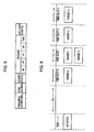
- Fig. 3 is a timing chart schematically showing polling processing according to this embodiment.
- the target within a communication range is ready to receive a polling command from the initiator.
- the target Upon receiving a polling command 301, the target determines a time slot for a response to the initiator according to a time slot number (TSN) specified in the frame of the polling command 301.
- TSN time slot number
- five targets are shown; however, any number of targets may be used as long as one or more than one target is used.
- a time slot is determined by the random number generated by the random number generator unit 223, as described in detail below.
- the target transits a polling response to the initiator in the allocated time slot after a fixed response time (T d ).
- T d a response time
- the target allocated time slot 2 sends a polling response 309 to the initiator after time T d and 2 x T s has passed.
- the initiator finishes receiving a polling response from the target. After the predetermined period of time, the series of polling operations is repeated; the initiator again issues and transmits a polling command to the target.
- Fig. 4 is a flowchart schematically showing the polling operation of this embodiment.
- polling is performed between one initiator and one target, by way of example. This example is merely illustrative, and polling may be performed between one initiator and N targets or between N initiators and N targets.
- the initiator issues and transmits a polling command to the target at predetermined time intervals according to the command executed by the state machine unit 205 (step S401).
- the timer unit 209 of the initiator starts counting a time limit for waiting for a polling response to be returned from the target.
- the time limit is preset as environment setting information by, for example, the "Config" command or the like.
- Fig. 5 is a schematic diagram of the frame format of the polling command of this embodiment.
- the frame of the polling command is constituted by a preamble portion containing a minimum of 48 bits, a 16-bit SYNC portion indicating the sync start position, an 8-bit length portion indicating the length (byte) obtained by adding one byte to the payload length (byte), a payload portion, and a 16-bit CRC code portion.
- the frame format of the polling command complies with, for example, ISO/IEC 18092.
- the added one byte of the length portion indicates the length of the length portion.
- the preamble portion is set to "0"
- the SYNC portion is set to hexadecimal "B24D”
- the length portion is set to "6”.
- the payload portion has hexadecimal "00”, “FF”, “FF”, and “00” each set in one byte in order from the portion on the right of the length portion shown in Fig. 5 , and also has "TSN (time slot number)".
- the "TSN” is set to a time slot number value, represented by hexadecimal "00", "01”, or "0F", and the remaining area is a preserved area (RSN).
- the target determines only time slot 0. For example, when the "TSN" is set to "0F", the target determines any time slot from time slots 0 to F.
- the polling command transmitted from the initiator is received by a target within the communication range (step S403).
- the target that receives (step S403) the polling command stores in advance the frame of a polling response in form of logic levels in order to instantaneously respond to the initiator.
- the target Upon receiving the polling command, according to the command executed by the state machine unit 205, the target checks for the system command by comparing the system code of the target stored in advance together with the frame of the polling response with the system code set in the received polling command (step S407).
- the system code set in the polling command is allocated "FFFF" in the payload portion at the second and third bytes from the left.
- the "FFFF” is a wildcard, which is applied to any system code.
- this target is regarded as an appropriate target that is to return a polling response, and the subsequent processing is performed. If an incorrect system code is set in the polling command, the state machine unit 205 stops polling due to a system code error. For example, when system code "1234" is stored, system code "1243" is regarded to be incorrect.
- the target checks for the 1-byte value on the left of the "TSN" of the payload portion of the polling command. If this value is "01”, the system code of this target is set in a pad portion of the frame of a polling response (step S409). In Fig. 5 , the 1-byte value on the left of the "TSN" is "00".
- the target does not set the system code in the pad portion of the polling response. If this 1-byte value is "01”, the target having system code "1234" sets "1234" in the pad portion of the polling response.
- the initiator that receives the polling response can obtain the system code of the target from the target, and can efficiently identify the target if the initiator does not know the system code of the target when transmitting the polling command.
- the frame format of the polling response is described in detail below.
- the target determines the time slot in which the polling response of this target is sent to the initiator (step S411).
- the time slot is determined based on the random number generated by the random number generator unit 223.
- slot time slot 0 is allocated when the time slot number ("TSN") value of the polling command is "00"
- time slot 0 or time slot 1 is allocated when the time slot number value is "01”
- any of time slots 0 to 3 is allocated when the time slot number value is "03”
- any of time slots 0 to 7 is allocated when the time slot number value is "07”.
- Fig. 6 is a chart showing the relationship between targets and the time slots allocated to the targets according to this embodiment.
- targets 1 and 3 are allocated time slot 1.
- the random number generator unit 223 of the target 1 and the random number generator unit 223 of the target 3 generate the same random number.
- a single time slot is allocated to a plurality of targets, and these targets return polling responses to the initiator in this time slot. At this time, collision occurs, and the initiator does not correctly receive the polling responses.
- the targets that are allocated time slot 1 transmit polling responses 305 and 307 to the initiator. These polling responses are transmitted substantially at the same time, which causes collision, and are not correctly received by the initiator.
- Fig. 7 is a schematic diagram of the frame format of the polling response of this embodiment.
- the frame format of the polling response complies with, for example, ISO/IEC 18092.
- the frame format of the polling response is constituted by a preamble portion containing a minimum of 48 bits, a 16-bit SYNC portion indicating the sync start position, a length portion indicating the length from a payload portion to the end (byte), the payload portion, and a 16-bit CRC code portion.
- the preamble portion is all set to "0"
- the SYNC portion is set to hexadecimal "B24D”
- the length portion is set to hexadecimal "12”.
- the payload portion has hexadecimal "01" set in one byte, an 8-byte NFCID2 portion, and an 8-byte pad portion in order from the portion on the right of the length portion shown in Fig. 7 (from the beginning position of the payload portion).
- the CRC code portion of the frame of the polling response has a remainder value given from generator polynomial (G(x)) when transmitting the polling response. Based on the remainder value set in the CRC code portion, the initiator performs a CRC to check for errors in the data.
- the polling response having the frame format described above is transmitted from the target in the allocated time slot, and is then received by the initiator within the receiving time limit for the initiator (step S415).
- the CRC unit 211 of the initiator receives bit-by-bit the polling response data demodulated from the polling responses transmitted from the target, which is sequentially supplied from the wireless communication I/F unit 213, and performs a CRC (step S415).
- the CRC is performed sequentially on every one byte included in the frame of the polling response.
- the CRC is performed while receiving the polling response from the target rather than after receiving all data included in the frame.
- the CRC is defined by, for example, ISO/IEC 18092.
- the generator polynomial (G(x)) for use in a CRC is given by Eq. (1) below, complying with ITU-T Recommendation V.41.
- This generator polynomial is merely illustrative, and, for example, ANSI CRC-16 generator polynomial may be used instead.
- G x x 16 + x 12 + x 5 + 1
- the CRC unit 211 of the initiator extracts one byte from the most significant bit (MSB) that is the beginning bit of the frame of the polling response data transmitted from the wireless communication I/F unit 213.
- MSB most significant bit
- the CRC unit 211 performs left bit-shifting to move the CRC value left, and a carry bit is XORed with Eq. (1).
- the CRC unit 211 performs left bit-shifting to move the extracted data left, and a carry bit is XORed with the CRC value and the data extracted at the first stage.
- the CRC unit 211 repeats the processing in the second and third stages seven times to process the remaining 7 bits of the 8 bits.
- the CRC unit 211 performs the processing in the first to fourth stages again.
- the state machine unit 205 sets "1" in a CRC error field in an error register of the FIFO unit 221.
- Fig. 8 is a schematic diagram of the error register of this embodiment.
- the error register is constituted by a "preliminary” field at the seventh bit, a "Temp error” field, an "RF error” field, a "BufferOvfl” field, a “Coll error” field, a “CRC error” field, a "Parity error” field, and a "protocol error” field.
- the "preliminary” field has “0" stored therein in advance.
- the "Temp error” field is set to "1" indicating a temp error when a temperature sensor detects heat, and the power of the antenna unit 219 is automatically turned off.
- the "RF error” field is set to "1" indicating an RF error when the other party does not operate in an active communication mode in the RF field within a certain period of time, which is specified by the NFCIP1 standard.
- the "BufferOvfl” field is set to "1" indicating a buffer overflow when the state machine unit 205 is to write data into the FIFO unit 221 that is full.
- the “Coll error” field is set to “1” when bit collision is detected, and is automatically initialized at the initial stage on the target side.
- the “Coll error” field is set to “1” only when the transmission rate is 106 kbps, and is set to "0" otherwise, e.g., when the transmission rate is 212 kbps or 424 kbps.
- the "CRC error” field is set to “1" when the CRC unit 211 detects an error as a result of CRC processing.
- the value set in the "CRC error” field is automatically initialized when reception begins.
- the "Parity error” field is set to "1" when an error is detected as a result of parity check.
- the value set in the "Parity error” field is automatically initialized when reception begins.
- the "Protocol error” field is set to "1" indicating a protocol error at least in any case of: (1) incorrect SOF (start of frame), (2) "1" set in the initiator of the control register when executing an "AntiColl” command, and (3) incorrect data length of received data.
- the state machine unit 205 determines whether or not the value set in the length portion of the received polling response is within a range preset by the initiator (step S419).
- the value set in the length portion of the polling response is 100 bytes, and the range preset by the initiator is 1 to 20 bytes.
- the value set in the length portion is out of the range, and therefore, no data is stored in the FIFO unit 221.
- the initiator may preset a range or a fixed value, e.g., "17" or "30".
- the state machine unit 205 After the value set in the length portion of the polling response is checked for (step S419), the state machine unit 205 stores the data of the polling response, exclusive of the CRC code portion, in the FIFO unit 221 (step S421).
- step S423 If the predetermined time limit for waiting for the polling response, which is counted by the timer unit 209 of the initiator, has elapsed (step S423), the initiator terminates the series of polling operations, and waits for the next polling command to be transmitted (step S425). After standby, when the predetermined period of time has elapsed, a polling command is transmitted again to the target, and the polling procedure described above (the processing of steps S401 to S423) is repeated.
- the wireless communication interface device 201 can independently perform time-critical polling even if the controller 111 accesses a register, such as the FIFO unit 221, at a low rate, or without control from the controller 111.
- the controller 111 of the wireless communication apparatus 101 need not have excessive capabilities, resulting in high design flexibility.
- the controller which is difficult to mount due to the cost of improvement in the art, can be connected with the wireless communication interface device 201, or a high-performance controller is not required. Thus, the cost can be reduced.
- the controller 111 and the wireless communication interface device 201 can be connected by a low-rate communication interface 203, such as a UART interface.
- the UART interface is a serial interface that only requires two lines for transmitting signals and that requires a smaller space than a parallel interface. Thus, the layout of other devices can be flexibly conducted.
- a parallel interface requires the parallel signal width (eight lines for 8 bits) for transmitting and receiving signals in a parallel manner, and also requires several timing control lines. Therefore, the parallel signal wiring is not suitable for lightweight and compact mobile devices, such as portable phones.
- Time-critical polling can be performed substantially solely by the wireless communication interface device 201, thus minimizing the size of the logic source compared to polling performed by a timer device (not shown), a CPU (not shown), etc., typically incorporated in the controller 111.
- the state machine unit 205, the CRC unit 211, the timer unit 209, the random number generator unit 223, the frame length check unit 226, the ID authenticating unit 227, the ID setting unit 228, and the time frame determining unit 229 of the wireless communication interface device 201 are implemented by hardware (logic circuits).
- the present invention is not limited to this embodiment.
- the state machine unit 205, the CRC unit 211, the timer unit 209, and the random number generator unit 223 may be implemented by a program composed of one or more than one module or component.
- wireless communication apparatus 101 and the wireless communication interface device 201 have been described in the context of wireless communication, the present invention is not limited to wireless communication, and may embrace, for example, communication via a line.
Landscapes
- Engineering & Computer Science (AREA)
- Physics & Mathematics (AREA)
- General Physics & Mathematics (AREA)
- Theoretical Computer Science (AREA)
- Computer Networks & Wireless Communication (AREA)
- Artificial Intelligence (AREA)
- Computer Vision & Pattern Recognition (AREA)
- Health & Medical Sciences (AREA)
- Toxicology (AREA)
- Business, Economics & Management (AREA)
- General Health & Medical Sciences (AREA)
- Microelectronics & Electronic Packaging (AREA)
- Electromagnetism (AREA)
- Accounting & Taxation (AREA)
- Strategic Management (AREA)
- General Business, Economics & Management (AREA)
- Signal Processing (AREA)
- Mobile Radio Communication Systems (AREA)
- Time-Division Multiplex Systems (AREA)
- Transceivers (AREA)
Claims (12)
- Drahtlose Kommunikationsvorrichtung (101a), die eine Nahfeldkommunikationstechnologie enthält, die Daten mit einer externen drahtlosen Vorrichtung (101b) in einer Drahtloskommunikationsreichweite kommuniziert, wobei die drahtlose Kommunikationsvorrichtung (101a) Folgendes umfasst:einen Controller (111a), der zum Steuern der drahtlosen Kommunikationsvorrichtung (101a) konfiguriert ist; undeine Drahtloskommunikations-Schnittstellenvorrichtung (201), die zum Empfangen von Antwortdaten unabhängig von der Steuerung des Controllers (111a) in Ansprechen auf an die externe drahtlose Vorrichtung (101b) gesendete Antwortanforderungsdaten konfiguriert ist, wobei die Drahtloskommunikations-Schnittstellenvorrichtung (201) Folgendes umfasst:eine Sendeeinheit (217), die zum Senden der Antwortanforderungsdaten konfiguriert ist;eine Zählereinheit (209), die zum Zählen der Zeit zum Bestimmen, ob ein Zeitgrenzwert zum Warten auf Antwortdaten verstrichen ist, konfiguriert ist;eine Speichereinheit (221), die zum Speichern der Antwortdaten konfiguriert ist;eine Empfangseinheit (215), die zum Empfangen erster Antwortdaten von der externen drahtlosen Vorrichtung (101b) und zum sofortigen Empfangen zweiter Antwortdaten ohne eine Anweisung von dem Controller (111a), wenn der Zeitgrenzwert nicht verstrichen ist, konfiguriert ist;eine Rahmenlängen-Prüfeinheit (226), die zum Prüfen einer Rahmenlänge der empfangenen Antwortdaten konfiguriert ist; undeine Fehlerdetektionseinheit (211), die zum Ausführen einer Fehlerdetektion an den Antwortdaten konfiguriert ist, wobei ein Fehlerdetektionsergebnis der Fehlerdetektionseinheit (211) in der Speichereinheit (221) gespeichert wird,wobei die Drahtloskommunikations-Schnittstellenvorrichtung (201) ferner eine Zustandsmaschineneinheit (205) umfasst, die die ausgeführte Verarbeitung unabhängig von dem Controller (111a) steuert, und wobei die Empfangseinheit (215) die zweiten Antwortdaten in Übereinstimmung mit einer Anweisung von der Zustandsmaschineneinheit (205) empfängt.
- Vorrichtung (101a) nach Anspruch 1, wobei die Rahmenlängen-Prüfeinheit (226) einen in den Antwortdaten eingestellten Rahmenwert gegenüber einem vorgegebenen Rahmenwert prüft, wobei der Rahmenwert die Rahmenlänge der Antwortdaten angibt.
- Vorrichtung (101a) nach Anspruch 1, wobei der Controller (111a) und die Drahtloskommunikations-Schnittstellenvorrichtung (201) durch eine serielle Schnittstelle verbunden sind.
- Vorrichtung (101a) nach Anspruch 1, wobei die Fehlerdetektionseinheit (211) einen in den Antwortdaten enthaltenen Fehlerdetektionscode entfernt und wobei die Antwortdaten, aus denen der Fehlerdetektionscode entfernt worden ist, in der Speichereinheit (221) gespeichert werden.
- Drahtlose Kommunikationsvorrichtung (101b), die eine Nahfeldkommunikationstechnologie enthält, die Daten mit einer externen drahtlosen Vorrichtung (101a) in einer Drahtloskommunikationsreichweite kommuniziert, wobei die drahtlose Kommunikationsvorrichtung (101b) Folgendes umfasst:einen Controller (111b), der zum Steuern der drahtlosen Kommunikationsvorrichtung (101b) konfiguriert ist; undeine Drahtloskommunikations-Schnittstellenvorrichtung (201), die zum Senden von Antwortdaten unabhängig von der Steuerung des Controllers (111b) in Ansprechen auf von der externen drahtlosen Vorrichtung (101a) empfangene Antwortanforderungsdaten konfiguriert ist, wobei die Drahtloskommunikations-Schnittstellenvorrichtung (201) Folgendes umfasst:eine Empfangseinheit (215), die zum Empfangen der Antwortdaten konfiguriert ist;eine Speichereinheit (221), die zum Speichern der Antwortdaten konfiguriert ist;eine Identifizierungsinformations-Authentifizierungseinheit (227), die zum Authentifizieren von Identifizierungsinformationen, die in den empfangenen Antwortanforderungsdaten enthalten sind, konfiguriert ist;eine Identifizierungsinformations-Einstelleinheit (228), die zum Einstellen von Identifizierungsinformationen der drahtlosen Kommunikationsvorrichtung (101b) in den Antwortdaten, wenn die Antwortanforderungsdaten Anforderungsinformationen, die Identifizierungsinformationen anfordern, enthalten, konfiguriert ist;eine Zeitrahmen-Bestimmungseinheit (209), die zum Bestimmen eines Zeitrahmens, in dem die Antwortdaten gesendet werden sollen, konfiguriert ist; undeine Sendeeinheit (217), die zum Senden der Antwortdaten in Übereinstimmung mit dem Zeitrahmen ohne eine Anweisung von dem Controller (111b) konfiguriert ist,wobei die Drahtloskommunikations-Schnittstellenvorrichtung (201) ferner eine Zustandsmaschineneinheit (205) umfasst, die die ausgeführte Verarbeitung unabhängig von dem Controller (111b) steuert.
- Vorrichtung (101b) nach Anspruch 5, wobei die Identifizierungsinformations-Authentifizierungseinheit (227) Identifizierungsinformationen, die in den Antwortanforderungsdaten enthalten sind, mit Identifizierungsinformationen der drahtlosen Kommunikationsvorrichtung (101b), die die Antwortanforderungsdaten empfängt, vergleicht.
- Vorrichtung (101b) nach Anspruch 5, wobei der Controller (111b) und die Drahtloskommunikations-Schnittstellenvorrichtung (201) durch eine serielle Schnittstelle verbunden sind.
- Antwortdaten-Verarbeitungsverfahren für eine drahtlose Kommunikationsvorrichtung (101a), die eine Nahfeldkommunikationstechnologie enthält, die einen Controller (111a) zum Kommunizieren von Daten mit einer externen drahtlosen Vorrichtung (101b) in einer Drahtloskommunikationsreichweite durch Anfordern (S401) von Antwortdaten und durch Warten auf die Antwortdaten von der externen drahtlosen Vorrichtung (101b) enthält, wobei das Antwortdaten-Verarbeitungsverfahren die folgenden Schritte umfasst:Ausführen einer Fehlerdetektion (S417) an den Antwortdaten ohne Steuerung des Controllers (111a); undPrüfen einer Rahmenlänge (S419) der Antwortdaten ohne Steuerung des Controllers (111a);Speichern (S421) der Antwortdaten und eines Fehlerdetektionsergebnisses ohne Steuerung des Controllers (111a);Zählen eines Zeitgrenzwerts (S423) zum Warten auf die Antwortdaten von der externen drahtlosen Vorrichtung (101b) ohne Steuerung des Controllers (111a);wobei die unabhängig von dem Controller (111a) ausgeführte Verarbeitung durch eine Zustandsmaschineneinheit (205) gesteuert wird.
- Verfahren nach Anspruch 8, wobei in dem Schritt des Prüfens einer Rahmenlänge (S419) ein in den Antwortdaten eingestellter Rahmenwert gegenüber einem vorgegebenen Rahmenwert geprüft wird, wobei der Rahmenwert die Rahmenlänge der Antwortdaten angibt.
- Verfahren nach Anspruch 8, wobei die gespeicherten Antwortdaten Antwortdaten umfassen, aus denen ein in der Fehlerdetektion verwendeter Fehlerdetektionscode entfernt worden ist.
- Antwortdaten-Verarbeitungsverfahren für eine drahtlose Kommunikationsvorrichtung (101b), die eine Nahfeldkommunikationstechnologie enthält, die einen Controller (111b) enthält, der Daten mit einer externen drahtlosen Vorrichtung (101a) in einer Drahtloskommunikationsreichweite durch Empfangen von Antwortanforderungsdaten (S403) von der externen drahtlosen Vorrichtung (101a) und durch Senden von Antwortdaten (S413) in Ansprechen auf die Antwortanforderungsdaten kommuniziert, wobei das Antwortdaten-Verarbeitungsverfahren die folgenden Schritte umfasst:Authentifizieren von Identifizierungsinformationen (S407), die in den empfangenen Antwortanforderungsdaten enthalten sind, ohne Steuerung von dem Controller (111b) ;Einstellen von Identifizierungsinformationen (S409) der drahtlosen Kommunikationsvorrichtung in den Antwortdaten ohne Steuerung des Controllers (111b), wenn die Antwortanforderungsdaten Anforderungsdaten, die Identifizierungsinformationen anfordern, enthalten;Bestimmen eines Zeitschlitzes (S411), in dem die Antwortdaten ohne Steuerung von dem Controller (111b) gesendet werden sollen; undSenden der Antwortdaten (S413) in Übereinstimmung mit dem Zeitrahmen,wobei die unabhängig von dem Controller (111a) ausgeführte Verarbeitung durch eine Zustandsmaschineneinheit (205) gesteuert wird.
- Verfahren nach Anspruch 11, wobei die in den Antwortanforderungsdaten enthaltenen Identifizierungsinformationen in dem Schritt des Authentifizierens von Identifizierungsinformationen (S407) mit Identifizierungsinformationen der drahtlosen Kommunikationsvorrichtung, die die Antwortanforderungsdaten empfängt, verglichen werden.
Applications Claiming Priority (2)
| Application Number | Priority Date | Filing Date | Title |
|---|---|---|---|
| JP2003389191A JP4483271B2 (ja) | 2003-11-19 | 2003-11-19 | 無線通信装置,無線通信装置の応答データ処理方法 |
| JP2003389191 | 2003-11-19 |
Publications (3)
| Publication Number | Publication Date |
|---|---|
| EP1533914A2 EP1533914A2 (de) | 2005-05-25 |
| EP1533914A3 EP1533914A3 (de) | 2007-08-15 |
| EP1533914B1 true EP1533914B1 (de) | 2014-07-02 |
Family
ID=34431570
Family Applications (1)
| Application Number | Title | Priority Date | Filing Date |
|---|---|---|---|
| EP04027332.8A Expired - Lifetime EP1533914B1 (de) | 2003-11-19 | 2004-11-17 | Drahtloses Kommunicationsgerät und zugehörige Verarbeitungsmethode für Antwortdaten |
Country Status (4)
| Country | Link |
|---|---|
| US (1) | US7711323B2 (de) |
| EP (1) | EP1533914B1 (de) |
| JP (1) | JP4483271B2 (de) |
| CN (1) | CN100347997C (de) |
Families Citing this family (51)
| Publication number | Priority date | Publication date | Assignee | Title |
|---|---|---|---|---|
| US7684754B2 (en) | 2003-06-03 | 2010-03-23 | Microsoft Corporation | Capacitive bonding of devices |
| US7822983B2 (en) * | 2003-08-21 | 2010-10-26 | Microsoft Corporation | Physical device bonding |
| US20140071818A1 (en) * | 2004-07-16 | 2014-03-13 | Virginia Innovation Sciences, Inc. | Method and system for efficient communication |
| US8316438B1 (en) | 2004-08-10 | 2012-11-20 | Pure Networks Llc | Network management providing network health information and lockdown security |
| US7925729B2 (en) | 2004-12-07 | 2011-04-12 | Cisco Technology, Inc. | Network management |
| KR101143785B1 (ko) * | 2004-09-30 | 2012-05-11 | 엔엑스피 비 브이 | 통신 장치, 반 이중 근거리 통신 방법 및 컴퓨터 판독가능 저장 매체 |
| US8478849B2 (en) * | 2004-12-07 | 2013-07-02 | Pure Networks LLC. | Network administration tool |
| US20060153384A1 (en) * | 2004-12-30 | 2006-07-13 | Microsoft Corporation | Extensible architecture for untrusted medium device configuration via trusted medium |
| WO2006077526A1 (en) | 2005-01-21 | 2006-07-27 | Koninklijke Philips Electronics, N.V. | Ordering content by mobile phone to be played on consumer devices |
| US7411911B2 (en) * | 2005-04-08 | 2008-08-12 | Cisco Technology, Inc. | Network availability status detection device and method |
| US7657255B2 (en) | 2005-06-23 | 2010-02-02 | Microsoft Corporation | Provisioning of wireless connectivity for devices using NFC |
| JP5017811B2 (ja) * | 2005-07-19 | 2012-09-05 | ソニー株式会社 | データ伝送システム,データ取得装置,データ取得方法,データ蓄積装置,データ送信方法,およびそのプログラム |
| CA2619262A1 (en) * | 2005-08-19 | 2007-02-22 | Astrazeneca Ab | Pyrazolone derivatives for the treatment of tuberculosis |
| US20070088732A1 (en) * | 2005-10-13 | 2007-04-19 | Yen-Fu Chen | Dynamic string length checking for off-line processing using client-side caching of database catalog |
| US7603365B2 (en) * | 2005-10-13 | 2009-10-13 | International Business Machines Corporation | System and method for capture and processing of overflow characters from user input |
| US7433877B2 (en) * | 2005-10-13 | 2008-10-07 | International Business Machines Corporation | System and method to dynamically check string length |
| US8032745B2 (en) * | 2005-12-20 | 2011-10-04 | International Business Machines Corporation | Authentication of I2C bus transactions |
| US20070218837A1 (en) * | 2006-03-14 | 2007-09-20 | Sony Ericsson Mobile Communications Ab | Data communication in an electronic device |
| JP4189410B2 (ja) * | 2006-06-12 | 2008-12-03 | 株式会社東芝 | 無線通信装置及び送信制御方法 |
| US8264991B2 (en) | 2007-04-27 | 2012-09-11 | Samsung Electronics Co., Ltd. | System and method for improving symmetry in data transfer in LLC layer of peer to peer NFC device |
| KR101408544B1 (ko) | 2007-05-07 | 2014-06-17 | 삼성전자주식회사 | 근거리무선통신의 데이터 송수신 방법 |
| US8700743B2 (en) * | 2007-07-13 | 2014-04-15 | Pure Networks Llc | Network configuration device |
| US9026639B2 (en) * | 2007-07-13 | 2015-05-05 | Pure Networks Llc | Home network optimizing system |
| US9491077B2 (en) * | 2007-07-13 | 2016-11-08 | Cisco Technology, Inc. | Network metric reporting system |
| JP4462341B2 (ja) | 2007-12-18 | 2010-05-12 | ソニー株式会社 | 情報処理装置および方法、並びにプログラム |
| EP2241031B1 (de) | 2007-12-20 | 2018-02-21 | Philips Intellectual Property & Standards GmbH | Umschaltung zwischen mehreren kopplungsmodi |
| JP4468437B2 (ja) * | 2007-12-27 | 2010-05-26 | フェリカネットワークス株式会社 | 情報処理装置、通信方法、及びプログラム |
| EP2534903A1 (de) * | 2010-02-12 | 2012-12-19 | InterDigital Patent Holdings, Inc. | Gruppenfunkruf für maschinenkommunikation |
| KR101610916B1 (ko) * | 2010-02-23 | 2016-04-11 | 삼성전자주식회사 | 근거리 통신을 위한 수신 장치와 그에 따른 통신 모드 검출방법 |
| US8724515B2 (en) | 2010-03-26 | 2014-05-13 | Cisco Technology, Inc. | Configuring a secure network |
| US8649297B2 (en) * | 2010-03-26 | 2014-02-11 | Cisco Technology, Inc. | System and method for simplifying secure network setup |
| CN103119887B (zh) * | 2010-10-01 | 2017-04-19 | 飞利浦灯具控股公司 | 用于对无线网络中的数据分组传输进行调度的设备和方法 |
| JP5135417B2 (ja) * | 2010-11-19 | 2013-02-06 | 株式会社東芝 | 無線通信装置 |
| CN102655547A (zh) * | 2011-03-01 | 2012-09-05 | 凹凸电子(武汉)有限公司 | 数据传输的电子设备、控制器及其控制方法 |
| CN105246047B (zh) * | 2011-07-05 | 2018-12-21 | 宏达国际电子股份有限公司 | 无线服务提供方法 |
| US8942628B2 (en) | 2011-11-28 | 2015-01-27 | Qualcomm Incorporated | Reducing power consumption for connection establishment in near field communication systems |
| US8903312B2 (en) | 2011-11-28 | 2014-12-02 | Qualcomm Incorporated | Modified connection establishment for reducing power consumption in near field communication systems |
| US8942623B2 (en) | 2011-12-02 | 2015-01-27 | Qualcomm Incorporated | Reducing NFC peer mode connection times |
| US20130198056A1 (en) * | 2012-01-27 | 2013-08-01 | Verizon Patent And Licensing Inc. | Near field communication transaction management and application systems and methods |
| US9054750B2 (en) | 2012-04-23 | 2015-06-09 | Qualcomm Incorporated | Methods and apparatus for improving RF discovery for peer mode communications |
| US8923761B2 (en) | 2012-05-17 | 2014-12-30 | Qualcomm Incorporated | Methods and apparatus for improving NFC RF discovery loop tuning based on device sensor measurements |
| US9736680B2 (en) * | 2012-06-27 | 2017-08-15 | Google Inc. | Techniques for transferring a data payload utilizing near-field communication |
| FR3001309B1 (fr) * | 2013-01-24 | 2015-01-09 | St Microelectronics Rousset | Procede de traitement d'erreurs de transmission, en particulier celles dues au bruit, lors d'une communication sans contact entre une carte et un lecteur. |
| US9195857B2 (en) * | 2013-09-30 | 2015-11-24 | Infineon Technologies Ag | Computational system |
| JP6201641B2 (ja) * | 2013-10-29 | 2017-09-27 | ソニー株式会社 | 情報処理装置、撮像装置、撮像システム、情報処理装置の制御方法、撮像装置の制御方法およびプログラム |
| CN105183076A (zh) * | 2015-08-20 | 2015-12-23 | 南京易迈海数码科技有限公司 | 数据采集查询pda的制备方法 |
| CN107334484B (zh) * | 2016-04-29 | 2020-09-25 | 上海西门子医疗器械有限公司 | Ct机的无线控制器、无线控制系统及ct机 |
| CN106648542B (zh) * | 2016-11-29 | 2019-07-26 | 建荣半导体(深圳)有限公司 | 随机数产生方法及相关装置、蓝牙芯片与电子设备 |
| JP6746101B2 (ja) * | 2017-11-02 | 2020-08-26 | 村田機械株式会社 | 搬送台車システム及び搬送台車システムでの通信方法 |
| US11023742B2 (en) * | 2018-09-07 | 2021-06-01 | Tusimple, Inc. | Rear-facing perception system for vehicles |
| CN113050052B (zh) * | 2021-03-08 | 2022-08-09 | 四川九洲空管科技有限责任公司 | 一种敌我识别系统多目标应答模拟方法 |
Family Cites Families (20)
| Publication number | Priority date | Publication date | Assignee | Title |
|---|---|---|---|---|
| US5519873A (en) * | 1990-08-31 | 1996-05-21 | International Business Machines Corporation | Apparatus for switching digital command execution between a general purpose microprocessor and dedicted execution logic |
| US5307351A (en) * | 1991-08-26 | 1994-04-26 | Universal Data Systems, Inc. | Data communication apparatus for adjusting frame length and method of operating same |
| CN1158526A (zh) * | 1996-08-28 | 1997-09-03 | 周运伟 | 一种近距离无线数据通信及数据处理系统 |
| JP2001186214A (ja) | 1999-10-13 | 2001-07-06 | Sony Corp | 通信装置、通信方法、通信方法を記録した記録媒体及び通信カード |
| US7546099B2 (en) * | 2000-02-16 | 2009-06-09 | Broadcom Corporation | Bluetooth baseband solution with reduced processor requirements and integrated host controller |
| JP2001307052A (ja) * | 2000-04-25 | 2001-11-02 | Nec Corp | 非接触icカード,リーダライタおよび非接触icカードシステムならびにその制御方法 |
| US6993049B2 (en) * | 2000-06-26 | 2006-01-31 | Koninklijke Philips Electronics N.V. | Communication system |
| GB0015454D0 (en) | 2000-06-26 | 2000-08-16 | Koninkl Philips Electronics Nv | Data delivery through beacons |
| EP1197909B1 (de) * | 2000-10-13 | 2004-09-08 | Matsushita Electric Industrial Co., Ltd. | Kontaktlose Chipkarte, Antwortverfahren und entsprechendes Programm |
| JP3514228B2 (ja) * | 2000-10-25 | 2004-03-31 | 日本電気株式会社 | 狭域無線連続通信方法とシステム |
| US6850147B2 (en) * | 2001-04-02 | 2005-02-01 | Mikos, Ltd. | Personal biometric key |
| JP2002345037A (ja) | 2001-05-17 | 2002-11-29 | Sony Corp | 携帯通信装置及び通信システム並びにその通信方法 |
| JP2003006509A (ja) | 2001-06-20 | 2003-01-10 | Hitachi Ltd | 通信装置,通信システム及び広告料算出方法 |
| JP3671880B2 (ja) * | 2001-07-18 | 2005-07-13 | ソニー株式会社 | 通信システムおよび方法、情報処理装置および方法、通信端末および方法、拡張装置、並びにプログラム |
| JP3617509B2 (ja) * | 2001-10-31 | 2005-02-09 | ソニー株式会社 | Icカード及び情報処理端末、3者間データ通信システム及び方法 |
| JP3595298B2 (ja) | 2001-11-29 | 2004-12-02 | 株式会社東芝 | 通信機能を備えた電子カードを接続可能な電子機器及びそれらを含むシステム並びに機能選択方法 |
| US7729776B2 (en) * | 2001-12-19 | 2010-06-01 | Cardiac Pacemakers, Inc. | Implantable medical device with two or more telemetry systems |
| US7011250B2 (en) | 2001-12-20 | 2006-03-14 | Matsushita Electric Industrial Co., Ltd. | IC card reader/writer, identification method and program |
| JP2003281453A (ja) * | 2002-03-20 | 2003-10-03 | Matsushita Electric Ind Co Ltd | 商品受け取りシステム |
| US7344074B2 (en) * | 2002-04-08 | 2008-03-18 | Nokia Corporation | Mobile terminal featuring smart card interrupt |
-
2003
- 2003-11-19 JP JP2003389191A patent/JP4483271B2/ja not_active Expired - Lifetime
-
2004
- 2004-11-11 US US10/987,759 patent/US7711323B2/en not_active Expired - Fee Related
- 2004-11-17 EP EP04027332.8A patent/EP1533914B1/de not_active Expired - Lifetime
- 2004-11-19 CN CNB2004100952275A patent/CN100347997C/zh not_active Expired - Fee Related
Also Published As
| Publication number | Publication date |
|---|---|
| CN1619573A (zh) | 2005-05-25 |
| HK1078971A1 (en) | 2006-03-24 |
| JP4483271B2 (ja) | 2010-06-16 |
| US7711323B2 (en) | 2010-05-04 |
| JP2005151413A (ja) | 2005-06-09 |
| EP1533914A2 (de) | 2005-05-25 |
| CN100347997C (zh) | 2007-11-07 |
| US20050111420A1 (en) | 2005-05-26 |
| EP1533914A3 (de) | 2007-08-15 |
Similar Documents
| Publication | Publication Date | Title |
|---|---|---|
| EP1533914B1 (de) | Drahtloses Kommunicationsgerät und zugehörige Verarbeitungsmethode für Antwortdaten | |
| US9277350B2 (en) | Method for data communication between a wireless device and a electronic device, and a data communication device | |
| US6945461B1 (en) | Compact multifunction card for electronic devices | |
| EP1443720A2 (de) | Verfahren zur Stationssuchverarbeitung und drahtloses Kommunikationsgerät | |
| JP6403122B2 (ja) | 通信デバイス及び通信システム | |
| EP2106188A1 (de) | Mobiles Kommunikationssystem, mobiles Kommunikationsverfahren, Basisstation und Mobilstation | |
| US20220173772A1 (en) | Exchange of data between a nfc reader and a dual nfc interface transponder | |
| EP1563445B1 (de) | Kontaktlose chipkarte | |
| JP3393127B2 (ja) | 通信端末装置およびそのデータ送信方法 | |
| JP3655597B2 (ja) | 電子機器、電子カード、及びカード識別方法 | |
| KR100562505B1 (ko) | 중앙 처리 장치의 개입없이 널 바이트 정보를 자동적으로전송할 수 있는 집적회로 카드 | |
| JP4426820B2 (ja) | 非接触icカード | |
| EP3454279A1 (de) | Multifunktions nahfeldkommunikations front-end an einem kassensystem | |
| JP2003248799A (ja) | Icカード用リーダライタ、識別方法、及びそのプログラム | |
| JP4597022B2 (ja) | 無線通信装置及び無線通信方法 | |
| US6574697B2 (en) | Data transfer equipment that provides high speed data transmission between data terminal equipment and data circuit terminating equipment | |
| US20030074261A1 (en) | Embedded payment for mobile printing | |
| JP2005182505A (ja) | データ転送制御装置および画像形成装置 | |
| HK1078971B (en) | Wireless communication apparatus and response data processing method therefor | |
| JPH09326800A (ja) | 無線通信装置及びその制御方法 | |
| JP2004129129A (ja) | 通信制御回路、通信制御装置、マイクロコンピュータ及び電子機器 | |
| KR100229605B1 (ko) | 씨디엠에이 이동통신 시스템 기지국의 다중 어드레스 비교 기능 을 갖는 에이치디엘씨 장치 | |
| CN116720541A (zh) | 一种通信方法及装置 | |
| JPH07321938A (ja) | 無線選択呼出受信機 | |
| KR20060054566A (ko) | 직접 메모리 접근을 이용하여 상태 정보를 출력하는 집적회로 카드 |
Legal Events
| Date | Code | Title | Description |
|---|---|---|---|
| PUAI | Public reference made under article 153(3) epc to a published international application that has entered the european phase |
Free format text: ORIGINAL CODE: 0009012 |
|
| AK | Designated contracting states |
Kind code of ref document: A2 Designated state(s): AT BE BG CH CY CZ DE DK EE ES FI FR GB GR HU IE IS IT LI LU MC NL PL PT RO SE SI SK TR |
|
| AX | Request for extension of the european patent |
Extension state: AL HR LT LV MK YU |
|
| PUAL | Search report despatched |
Free format text: ORIGINAL CODE: 0009013 |
|
| AK | Designated contracting states |
Kind code of ref document: A3 Designated state(s): AT BE BG CH CY CZ DE DK EE ES FI FR GB GR HU IE IS IT LI LU MC NL PL PT RO SE SI SK TR |
|
| AX | Request for extension of the european patent |
Extension state: AL HR LT LV MK YU |
|
| 17P | Request for examination filed |
Effective date: 20080115 |
|
| AKX | Designation fees paid |
Designated state(s): DE FR GB |
|
| 17Q | First examination report despatched |
Effective date: 20091111 |
|
| REG | Reference to a national code |
Ref country code: DE Ref legal event code: R079 Ref document number: 602004045387 Country of ref document: DE Free format text: PREVIOUS MAIN CLASS: H04B0005020000 Ipc: G06K0007000000 |
|
| GRAP | Despatch of communication of intention to grant a patent |
Free format text: ORIGINAL CODE: EPIDOSNIGR1 |
|
| RIC1 | Information provided on ipc code assigned before grant |
Ipc: G06K 7/00 20060101AFI20140103BHEP Ipc: G07F 7/08 20060101ALI20140103BHEP Ipc: H04B 5/02 20060101ALI20140103BHEP Ipc: G07F 7/10 20060101ALI20140103BHEP Ipc: G06K 7/10 20060101ALI20140103BHEP Ipc: G06Q 20/34 20120101ALI20140103BHEP |
|
| INTG | Intention to grant announced |
Effective date: 20140131 |
|
| RIN1 | Information on inventor provided before grant (corrected) |
Inventor name: FUJII, KUNHIDE |
|
| GRAS | Grant fee paid |
Free format text: ORIGINAL CODE: EPIDOSNIGR3 |
|
| GRAA | (expected) grant |
Free format text: ORIGINAL CODE: 0009210 |
|
| AK | Designated contracting states |
Kind code of ref document: B1 Designated state(s): DE FR GB |
|
| REG | Reference to a national code |
Ref country code: GB Ref legal event code: FG4D |
|
| REG | Reference to a national code |
Ref country code: DE Ref legal event code: R096 Ref document number: 602004045387 Country of ref document: DE Effective date: 20140814 |
|
| REG | Reference to a national code |
Ref country code: DE Ref legal event code: R097 Ref document number: 602004045387 Country of ref document: DE |
|
| REG | Reference to a national code |
Ref country code: DE Ref legal event code: R084 Ref document number: 602004045387 Country of ref document: DE |
|
| PLBE | No opposition filed within time limit |
Free format text: ORIGINAL CODE: 0009261 |
|
| STAA | Information on the status of an ep patent application or granted ep patent |
Free format text: STATUS: NO OPPOSITION FILED WITHIN TIME LIMIT |
|
| REG | Reference to a national code |
Ref country code: DE Ref legal event code: R084 Ref document number: 602004045387 Country of ref document: DE Effective date: 20150410 |
|
| 26N | No opposition filed |
Effective date: 20150407 |
|
| REG | Reference to a national code |
Ref country code: FR Ref legal event code: PLFP Year of fee payment: 12 |
|
| REG | Reference to a national code |
Ref country code: FR Ref legal event code: PLFP Year of fee payment: 13 |
|
| REG | Reference to a national code |
Ref country code: FR Ref legal event code: PLFP Year of fee payment: 14 |
|
| PGFP | Annual fee paid to national office [announced via postgrant information from national office to epo] |
Ref country code: DE Payment date: 20181120 Year of fee payment: 15 |
|
| PGFP | Annual fee paid to national office [announced via postgrant information from national office to epo] |
Ref country code: GB Payment date: 20181120 Year of fee payment: 15 Ref country code: FR Payment date: 20181123 Year of fee payment: 15 |
|
| REG | Reference to a national code |
Ref country code: DE Ref legal event code: R119 Ref document number: 602004045387 Country of ref document: DE |
|
| GBPC | Gb: european patent ceased through non-payment of renewal fee |
Effective date: 20191117 |
|
| PG25 | Lapsed in a contracting state [announced via postgrant information from national office to epo] |
Ref country code: FR Free format text: LAPSE BECAUSE OF NON-PAYMENT OF DUE FEES Effective date: 20191130 Ref country code: GB Free format text: LAPSE BECAUSE OF NON-PAYMENT OF DUE FEES Effective date: 20191117 Ref country code: DE Free format text: LAPSE BECAUSE OF NON-PAYMENT OF DUE FEES Effective date: 20200603 |