EP1533802A1 - Zwischenprodukt fur ein optisches aufzeichnungsmedium und verfahren zur herstellung eines optischen aufzeichnungsmediums - Google Patents
Zwischenprodukt fur ein optisches aufzeichnungsmedium und verfahren zur herstellung eines optischen aufzeichnungsmediums Download PDFInfo
- Publication number
- EP1533802A1 EP1533802A1 EP03741169A EP03741169A EP1533802A1 EP 1533802 A1 EP1533802 A1 EP 1533802A1 EP 03741169 A EP03741169 A EP 03741169A EP 03741169 A EP03741169 A EP 03741169A EP 1533802 A1 EP1533802 A1 EP 1533802A1
- Authority
- EP
- European Patent Office
- Prior art keywords
- recording medium
- optical recording
- central
- resin
- disk
- Prior art date
- Legal status (The legal status is an assumption and is not a legal conclusion. Google has not performed a legal analysis and makes no representation as to the accuracy of the status listed.)
- Withdrawn
Links
- 230000003287 optical effect Effects 0.000 title claims abstract description 56
- 238000004519 manufacturing process Methods 0.000 title claims abstract description 30
- 238000000034 method Methods 0.000 title description 37
- 239000013067 intermediate product Substances 0.000 title 1
- 239000011347 resin Substances 0.000 claims abstract description 83
- 229920005989 resin Polymers 0.000 claims abstract description 83
- 239000002346 layers by function Substances 0.000 claims abstract description 39
- 238000000465 moulding Methods 0.000 claims description 3
- 239000010410 layer Substances 0.000 abstract description 41
- 238000004528 spin coating Methods 0.000 abstract description 25
- 239000000543 intermediate Substances 0.000 description 131
- 239000000758 substrate Substances 0.000 description 35
- 230000002093 peripheral effect Effects 0.000 description 10
- 238000010276 construction Methods 0.000 description 9
- 239000011241 protective layer Substances 0.000 description 9
- 238000012423 maintenance Methods 0.000 description 5
- 238000004544 sputter deposition Methods 0.000 description 5
- 238000004140 cleaning Methods 0.000 description 4
- 238000003860 storage Methods 0.000 description 4
- 238000009826 distribution Methods 0.000 description 3
- 230000015572 biosynthetic process Effects 0.000 description 2
- 238000002474 experimental method Methods 0.000 description 2
- 239000012782 phase change material Substances 0.000 description 2
- 229920000515 polycarbonate Polymers 0.000 description 2
- 239000004417 polycarbonate Substances 0.000 description 2
- 229910052782 aluminium Inorganic materials 0.000 description 1
- 239000011248 coating agent Substances 0.000 description 1
- 238000000576 coating method Methods 0.000 description 1
- 238000005520 cutting process Methods 0.000 description 1
- 238000010586 diagram Methods 0.000 description 1
- 229910052737 gold Inorganic materials 0.000 description 1
- 239000000049 pigment Substances 0.000 description 1
- 229910052709 silver Inorganic materials 0.000 description 1
- 238000009987 spinning Methods 0.000 description 1
- 238000003892 spreading Methods 0.000 description 1
Images


Classifications
-
- G—PHYSICS
- G11—INFORMATION STORAGE
- G11B—INFORMATION STORAGE BASED ON RELATIVE MOVEMENT BETWEEN RECORD CARRIER AND TRANSDUCER
- G11B7/00—Recording or reproducing by optical means, e.g. recording using a thermal beam of optical radiation by modifying optical properties or the physical structure, reproducing using an optical beam at lower power by sensing optical properties; Record carriers therefor
- G11B7/24—Record carriers characterised by shape, structure or physical properties, or by the selection of the material
- G11B7/26—Apparatus or processes specially adapted for the manufacture of record carriers
- G11B7/266—Sputtering or spin-coating layers
-
- G—PHYSICS
- G11—INFORMATION STORAGE
- G11B—INFORMATION STORAGE BASED ON RELATIVE MOVEMENT BETWEEN RECORD CARRIER AND TRANSDUCER
- G11B7/00—Recording or reproducing by optical means, e.g. recording using a thermal beam of optical radiation by modifying optical properties or the physical structure, reproducing using an optical beam at lower power by sensing optical properties; Record carriers therefor
- G11B7/24—Record carriers characterised by shape, structure or physical properties, or by the selection of the material
- G11B7/26—Apparatus or processes specially adapted for the manufacture of record carriers
Definitions
- the present invention relates to an intermediate for an optical recording medium, for manufacturing an optical recording medium that has a central mounting hole formed in a central portion thereof and one or more kinds of functional layers formed on a surface thereof, for enabling at least one of information recording and information reproduction, and a method of manufacturing the optical recording medium using the intermediate.
- an optical recording medium of the above-mentioned kind such as a CD (Compact Disk) or a DVD (Digital Versatile Disk)
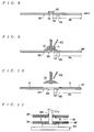
- a disk-shaped substrate DP having a shape shown in FIG. 9 is molded by injecting resin into a mold having a stamper set therein.
- a central mounting hole (also used as a central mounting hole of the optical recording medium) MH is formed in the central portion of the disk-shaped substrate DP.
- fine protrusions/depressions such as grooves are formed in an area (recording area RA) of one surface (upper surface as viewed in the figure) of the disk-shaped substrate DP, where functional layers, referred to hereinafter, are to be formed.
- an annular projection (so-called stock ring) SR is formed on the other surface (lower surface as viewed in the figure) of the disk-shaped substrate DP.
- the annular projection SR is formed in a zone between a chucking area CA adjacent to the central mounting hole MH toward the inner periphery of the disk-shaped substrate DP and the recording area RA. As shown in FIG.
- molded disk-shaped substrates DP are stored in a state stacked on a stacker 51 with the central mounting hole MH of each disk-shaped substrate DP being fitted on a stacker pole 51a of the stacker 51.
- the disk-shaped substrates DP are stacked with spaces created therebetween by the annular projections SR. Therefore, even if vibrations are applied to the disk-shaped substrates DP in this state, the disk-shaped substrates DP are prevented from being greatly inclined, so that interference between the disk-shaped substrates DP can be avoided, which prevents the surfaces of the disk-shaped substrates DP from being damaged or flawed.
- the disk-shaped substrates DP are sequentially taken out from the stacker 51, and various functional layers (reflection layer, recording layer, protective layer, etc.) are sequentially formed in the recording area RA of the one surface of each disk-shaped substrate DP to thereby complete an optical recording medium (not shown). Thereafter, the completed optical recording media are stored on the stacker 51 similarly to the disk-shaped substrates DP.
- part of the functional layers e.g. the protective layer
- a method which applies resin R using a disk-shaped member DI, because this method facilitates formation of functional layers (resin layers) substantially uniform in thickness particularly in radial directions.
- the disk-shaped member DI is placed on a disk-shaped substrate DP such that the member DI covers the central mounting hole MH, and then the resin R is dropped from a nozzle NZ onto the disk-shaped member DI for spin coating. Thereafter, as shown in FIG. 10, the disk-shaped member DI is removed from the disk-shaped substrate DP, and the disk-shaped substrate DP coated with the resin R up to the outer periphery of the upper surface thereof is conveyed to a site for executing the curing treatment.
- the disk-shaped substrate DP is normally carried by either of a method which conveys the disk-shaped substrate DP by sucking an uncoated area (area adjacent to the central mounting hole MH) thereof which was covered by the disk-shaped member DI by a suction device (not shown) and a method which conveys the disk-shaped substrate DP by making use of the central mounting hole MH by a mechanical chuck (not shown).
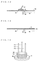
- an intermediate ME shown in FIG. 12, for a disk-shaped substrate, is prepared by the same method as employed in manufacturing the disk-shaped substrate DP.
- a central mounting hole MH is not formed through the intermediate ME, but fine protrusions/depressions (not shown) such as grooves are formed in one surface (upper surface as viewed in the figure) thereof, and an annular projection SR is formed on the lower surface (lower surface as viewed in the figure), similarly to the disk-shaped substrate DP.
- various functional layers (reflection layer, recording layer, protective layer, etc.) are sequentially formed in a recording area RA of the one surface of the intermediate ME.
- the spin coating method is employed to apply resin R to the intermediate ME for formation of each of the functional layers, the resin R is dropped from a nozzle NZ onto the central portion of the intermediate for spin coating, as shown in FIG.
- the layer FL the central portion of the intermediate ME having all the functional layers (hereinafter collectively referred to as "the layer FL") formed on the one surface thereof is blanked by presswork to form a central mounting hole MH.
- the disk-shaped member DI since the disk-shaped member DI is not used for performing spin coating, it is possible to dispense with troublesome maintenance of the disk-shaped member DI.
- the present inventors found out the following problems to be solved:
- the intermediate ME without the central mounting hole MH is prepared, and then the layer FL is formed on the intermediate ME, whereafter the central mounting hole MH is formed by presswork. Therefore, in the step of forming functional layers by the spin coating method, since the central mounting hole MH is not yet formed in the central portion of the intermediate ME when the intermediate ME coated with uncured resin R is to be conveyed to the site for carrying out the curing treatment, it is impossible to use the aforementioned mechanical chuck. Further, since the area that is not coated with the resin R does not exist on the intermediate ME, it is also impossible to use the aforementioned suction device.
- a method can be contemplated, for example, which uses a device additionally provided for partially curing the resin R to cure part of the resin R on the central portion of the intermediate ME, for allowing the suction device to suck the cured portion.
- this method raises a problem to be solved that it newly requires the cost of the device for partially curing the resin R. Further, the method raises another problem to be solved that since the step of partially curing the resin R is added, manufacturing time is increased, causing reduced production of optical recording media 1 per unit time, resulting in an increase in manufacturing costs.
- the intermediates ME held within the stack poles 61a, 61a, and 61a have respective outer peripheral edges thereof supported by the stack poles 61a, 61a, and 61a.
- another method can be contemplated which uses a storage case having a plurality of grooves formed therein at equal space intervals, each for receiving the outer peripheral edge of an intermediate ME, to store intermediates ME in a vertical position in parallel with each other in the side-by-side arrangement.
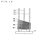
- each intermediate ME has its outer peripheral edge supported only by the stack poles 61a, 61a, and 61a, when vibrations are applied to a plurality of intermediates ME stacked one upon another, the intermediates ME easily lose their balance and are tilted as shown in FIG. 15. This raises a problem to be solved.
- the area occupied by the storage case is laterally increased in accordance with an increase in the number of stored intermediates ME, and hence in comparison with the storing method using the stackers 51 and 61, it is difficult to allocate enough space for the storage case when the number of intermediates ME to be stored is large. This also raises a problem to be solved.
- the present invention has been made to solve the above described problems, and it is a main object thereof to provide an intermediate for an optical recording medium, which can be uniformly coated with resin by the spin coating method without using a disk-shaped member, stored in a stable state while saving space, and conveyed by an existing conveyor device even when the resin applied thereto remains uncured. Further, it is a main object thereof to provide a method of manufacturing an optical recording medium which can be uniformly coated with resin by the spin coating method without using a disk-shaped member, and conveyed by an existing conveyor device even when the resin applied thereto remains uncured.
- the intermediate for an optical recording medium has a central mounting hole formed in a central portion thereof and one or more kinds of functional layers formed on a surface thereof, for enabling at least one of information recording and information reproduction, the intermediate being produced beforehand for manufacturing the optical recording medium, wherein the intermediate has a provisional central hole smaller in diameter than the central mounting hole formed in a central portion thereof.
- a provisional central hole having a diameter smaller than that of a central mounting hole formed in the optical recording medium is formed in the central portion of the intermediate, whereby in performing spin coating, it is possible to drop resin in the vicinity of the center of the intermediate without using a disk-shaped member, so that a layer of the resin having a substantially uniform thickness can be formed.
- This makes it possible to dispense with the disk-shaped member, and therefore, unnecessary to carry out maintenance, such as cleaning, of the same, so that costs of manufacturing and maintaining the disk-shaped member can be eliminated.
- the provisional central hole it is possible to hold the intermediate using a mechanical chuck conventionally in general use. Therefore, it is possible to avoid introduction of any new apparatus for conveying intermediates, so that it is possible to cut expenditures in plant and equipment.
- the provisional central hole is formed to have an inner diameter not smaller than 2 mm, and it is more preferred that the same is formed to have an inner diameter not smaller than 3 mm.
- a hollow cylindrical portion having an outer diameter smaller than the diameter of the central mounting hole and an inner diameter not smaller than a diameter of the provisional central hole, and having a central axis thereof aligned with a center of the provisional central hole, is formed on a surface on which the functional layers are to be formed, in a manner protruding therefrom.
- This construction makes it possible to drop the resin along the outer peripheral surface of the hollow cylindrical portion, thereby supplying the required amount of resin at a location closer to the center of the intermediate than a location away therefrom by the diameter of the central mounting hole without letting the resin enter the provisional central hole. Therefore, the thickness distribution of the layer of the resin formed by the spin coating method can be made more uniform.
- the hollow cylindrical portion is formed to have an outer diameter not larger than 10 mm, and it is more preferred that the hollow cylindrical portion is formed to have an outer diameter not larger than 7 mm. If the outer diameter of the hollow cylindrical portion is set to not larger than 10 mm, when resin is applied by the spin coating method, it is possible to apply the resin substantially uniformly by holding variation in the thickness of the layer of the resin in the recording area of the intermediate e.g. within approximately 5 ⁇ m. Further, by setting the outer diameter of the hollow cylindrical portion to not larger than 7 mm, it is possible to form a more uniform resin film by holding variation in the thickness of the applied resin e.g. within approximately 3 ⁇ m.
- the hollow cylindrical portion is formed such that a length of protrusion thereof from the surface on which the functional layers are to be formed is not smaller than 0.5 mm, and more preferably not smaller than 1.0 mm. Due to this construction, when spin coating is performed, it is possible to drop a required amount of resin, and prevent the dropped resin from entering the provisional central hole, thereby reducing variation in the thickness of the resin to form a uniformly coated resin layer. Further, it is preferred that the hollow cylindrical portion is formed such that the inner diameter thereof is equal to the diameter of the provisional central hole. Due to this construction, it is possible to bring the chucks of the mechanical chuck into contact not only with the inner surface of the provisional central hole, but also with the inner surface of the hollow cylindrical portion. This makes it possible to increase the contact area between the surfaces of the chucks and the intermediate and increase the frictional force generated between the surfaces of the chucks and the intermediate, so that the holding of the intermediate by the mechanical chuck can be made stable.
- a method of manufacturing an optical recording medium comprises, when an optical recording medium is manufactured which has a central mounting hole formed in a central portion thereof and one or more kinds of functional layers formed on a surface thereof, for enabling at least one of information recording and information reproduction, at least the steps of an intermediate-preparing step of preparing any one of the aforementioned intermediates by resin molding, a functional layer-forming step of forming the functional layers on the surface of the prepared intermediate, and a central hole-forming step of forming the central mounting hole through the intermediate having the one or more kinds of functional layers formed thereon.
- the optical recording medium is manufactured by performing the intermediate-preparing step of preparing any one of the aforementioned intermediates by resin molding, the functional layer-forming step of forming the functional layers on the surface of the prepared intermediate, and the central hole-forming step of forming the central mounting hole through the intermediate having all the functional layers formed thereon. Therefore, in performing spin coating, it is possible to drop resin in the vicinity of the center of the intermediate without using a disk-shaped member, so that a layer of the applied resin can be made substantially uniform in thickness.
- This method makes it possible to dispense with the disk-shaped member, and therefore, unnecessary to carry out maintenance, such as cleaning, of the same, so that costs of manufacturing and maintaining the disk-shaped member can be eliminated.
- the provisional central hole it is possible to hold the intermediate using the mechanical chuck conventionally in general use. Therefore, it is possible to avoid introduction of any new apparatus for conveying intermediates, and therefore, it is possible to cut expenditures in plant and equipment.
- FIG. 1 is a side cross-sectional view showing the construction of an optical recording medium 1 manufactured by using an intermediate ME1 according to an embodiment of the present invention
- FIG. 2 is a perspective view useful in explaining a method of conveying the intermediate ME1 using a mechanical chuck 41;
- FIG. 3 is a perspective view useful in explaining a method of storing intermediates ME1 using a stacker 51;
- FIG. 4 is a side cross-sectional view of the intermediate ME1 according to the embodiment of the present invention.
- FIG. 5 is a side cross-sectional view showing the FIG. 4 intermediate ME1 having a layer FL formed thereon;
- FIG. 6 is a side cross-sectional view showing the FIG. 4 intermediate ME1 having resin R dropped thereon;
- FIG. 7 is a diagram useful in explaining an intermediate-holding operation by the mechanical chuck 41.
- FIG. 8 is a side cross-sectional view of another intermediate ME2 according to the embodiment of the present invention.
- FIG. 9 is a side cross-sectional view of a disk-shaped substrate DP with a disk-shaped member DI placed thereon and resin R dropped on the disk-shaped member;
- FIG. 10 is a side cross-sectional view of the FIG. 9 disk-shaped substrate DP having a layer of the resin R formed thereon by the spin coating method;
- FIG. 11 is a cross-sectional view showing a state of disk-shaped substrates DP being stored on the stacker 51;
- FIG. 12 is a side cross-sectional view useful in explaining a method of manufacturing the optical recording medium 1 by using another intermediate ME developed by the present inventors, and showing the intermediate ME having the resin R applied to a central portion thereof;
- FIG. 13 is a side cross-sectional view of the FIG. 12 intermediate ME coated with the resin R by the spin coating method
- FIG. 14 is a perspective view of intermediates ME in a state stored on a stacker 61.
- FIG. 15 is a side cross-sectional view showing the intermediates ME stacked on the stacker 61 which have lost their balance and tilted due to vibrations or the like.
- the optical recording medium 1 is formed by forming a layer FL on one surface (upper surface, as viewed in the figure) of a disk-shaped substrate DP.
- the disk-shaped substrate DP is formed e.g. of a transparent resin (polycarbonate, for example) and has a disk shape with a thickness of approximately 1.1 mm and a diameter of approximately 120 mm.
- the disk-shaped substrate DP has a central portion thereof formed with a central mounting hole MH having a diameter of approximately 15 mm, and within a recording area RA on the one surface of the disk-shaped substrate DP, there are formed fine protrusions/depressions, such as grooves.
- the layer FL is comprised of various functional layers, such as a reflection layer, a recording layer, and a protective layer (cover layer), sequentially deposited from the disk-shaped substrate DP side in the mentioned order.
- the layer FL has a thickness of approximately 0.1 mm in total.
- At least the protective layer formed of resin (light-transmitting resin) coated all over the one surface of the disk-shaped substrate DP is a functional layer formed by the spin coating method, while the reflection layer formed of Ag, Au, Al, or the like within the recording area RA is a functional layer formed by the sputtering method. Further, when a phase change material is used to form the recording layer, the recording layer is also a functional layer formed by the sputtering method.
- a stamper (not shown) having a pattern for forming fine protrusions/depressions, such as grooves, formed on a surface thereof, is set in a mold assembly (not shown), and a resin is injected into a cavity of the mold assembly to thereby mold an intermediate ME1 (intermediate-preparing step).
- the intermediate ME1 is formed of a transparent resin (polycarbonate, for example) and has a disk shape with a thickness of approximately 1.1 mm and a diameter of approximately 120 mm.
- the intermediate ME1 has a central portion thereof formed with a provisional central hole TH smaller in diameter than the central mounting hole MH of the optical recording medium 1.
- the provisional central hole TH is used, as shown in FIG.
- the provisional central hole TH is also used, as shown in FIG. 3, for inserting a stack pole 51a of a stacker 51 therethrough for placing the intermediate ME1 on the stacker 51 for storage.
- the diameter of the stack pole 51a is set to be slightly smaller than that of the provisional central hole TH. In this case, when the strengths of the chucks 43 and the stack pole 51a are considered, reduction of the sizes and diameters of these is inevitably limited. Therefore, the diameter of the provisional central hole TH is set to not smaller than 2 mm, and preferably not smaller than 3 mm. In the intermediate ME1 according to the present embodiment, the diameter of the provisional central hole TH is set to 4 mm, by way of example.
- the hollow cylindrical portion RI on one surface of the intermediate ME1, there is formed a hollow cylindrical portion RI, and the central axis of the hollow cylindrical portion RI is configured to be aligned with the center of (coaxial with) the provisional central hole TH.
- the hollow cylindrical portion RI has an inner diameter thereof set to be equal to the diameter (4 mm) of the provisional central hole TH, and protrudes from the rim of the provisional central hole TH.
- the hollow cylindrical portion RI is blanked off simultaneously when the central portion of the intermediate ME1 is blanked by presswork to form the central mounting hole MH.
- the outer diameter of the hollow cylindrical portion RI is not larger than the diameter of the central mounting hole MH at the maximum (not larger than 15 mm). Further, when a resin R is applied to the one surface of the intermediate ME1 by the spin coating method, it is necessary to drop the resin R from a nozzle NZ onto the vicinity of the outer peripheral surface of the hollow cylindrical portion RI. In doing this, it has been found by experiment that the resin R is required to be dropped within approximately 10 mm of the center of the intermediate ME1 so as to substantially uniformly apply the resin R while holding variation in the thickness of the layer of the resin R at least in the recording area RA, within approximately 5 ⁇ m.
- the outer diameter of the hollow cylindrical portion RI is set to approximately not larger than 10 mm, and preferably approximately not larger than 7 mm.
- the outer diameter of the hollow cylindrical portion RI is set to 6 mm, by way of example.
- the length of projection of the hollow cylindrical portion RI from the one surface of the intermediate ME1 is required to be set to not smaller than 0.5 mm so as to allow a required amount of resin R to be dropped as well as to prevent the dropped resin R from entering the provisional central hole TH, while suppressing the variation in the thickness of the resin R in the recording area RA.
- the length of projection of the hollow cylindrical portion RI is preferably set to not smaller than 1 mm.
- the length of projection of the hollow cylindrical portion RI is set to 2 mm, by way of example.
- the other part of the intermediate ME1 than the central portion to be blanked by presswork is identical in construction to the corresponding part of the optical recording medium 1. Therefore, within the recording area RA on the one surface of the intermediate ME1, there are formed fine protrusions/depressions, such as grooves. Further, on the other surface of the intermediate ME1, an annular projection SR is formed. Intermediates ME1 molded as above are stored in a state vertically stacked one upon another, as shown in FIG. 3, using the stacker 51.
- the layer FL comprised of a plurality of functional layers is formed on the one surface of the intermediate ME1 by the sputtering method and the spin coating method (functional layer-forming step).
- a functional layer formed by the sputtering method e.g. the reflection layer, or the recording layer formed of a phase change material
- the spin coating method e.g. the spin coating method
- the protective layer is formed by dropping the resin R directly from the nozzle NZ onto the vicinity of the outer peripheral surface of the hollow cylindrical portion RI, as shown in FIG. 6, and then spreading (drawing) the resin R to the outer periphery of the intermediate ME1 by spinning the intermediate ME1, and curing the spread resin R.
- the outer diameter of the hollow cylindrical portion RI is set to approximately not larger than 10 mm, it is possible to drop the resin R onto an area close to the center of the intermediate ME1 without using a disk-shaped member DI.
- the functional layer can be formed by the spin coating method such that the layer thickness distribution of the resin R is substantially uniform.
- the intermediate ME1 coated with the resin R is conveyed to a site where the next step (curing treatment) is to be executed, the intermediate ME1 is held by the mechanical chuck 41 shown in FIG. 2 for conveyance.
- the mechanical chuck 41 is comprised of an actuator 42 and the three chucks 43, 43, and 43 each extending downward from the lower surface of the actuator 42.
- the chucks 43, 43, and 43 are arranged at equal space intervals along the same circumference, and each of the chucks 43, 43, and 43 has an upper end thereof attached to the actuator 42 in a manner pivotally movable in a radial direction.
- the actuator 42 has a capability of pivotally moving each of the chucks 43, 43, and 43 with the upper end thereof as a pivot to thereby move the chucks 43, 43, and 43, as shown in FIG.
- the mechanical chuck 41 First, as shown in FIG. 2, the chucks 43, 43, and 43 in the diametrically reduced state are inserted into the provisional central hole TH. Then, the chucks 43, 43, and 43 are pivotally moved toward the diametrically expanded state by the actuator 42. At this time, although the chucks 43, 43, and 43 are restricted from moving outward at a time point (position shown as "C" in FIG.
- the mechanical chuck 41 holds the intermediate ME1 such that it can convey the intermediate ME1 without dropping the same, by frictional force generated between the surfaces of the chucks 43, 43, and 43 and the inner surface of the provisional central hole TH.
- the diameter of the provisional central hole TH and the inner diameter of the hollow cylindrical portion RI are set to be equal to each other, so that the chucks 43, 43, and 43 are brought into contact not only with the inner surface of the provisional central hole TH but also with the inner surface of the hollow cylindrical portion RI.
- the central portion of the intermediate ME1 and the layer FL formed on the one surface of the intermediate ME1 (within approximately 15 mm diameter having the central axis of the intermediate ME1 in the center) is blanked (central hole-forming step).
- the hollow cylindrical portion RI and the provisional central hole TH are removed, and simultaneously, a central mounting hole MH is newly formed, whereby the optical recording medium 1 shown in FIG. 1 is manufactured.
- the intermediate ME1 for the disk-shaped substrate DP since it has the central portion thereof formed with the provisional central hole TH smaller in diameter than the central mounting hole MH, it is possible to drop the resin R onto the vicinity of the center of the intermediate ME1 without using the disk-shaped member DI, so that a layer of the resin R can be formed by the spin coating method such that the layer has a substantially uniform thickness. Further, by making use of the provisional central hole TH, it is possible to positively hold the intermediate ME1 by the mechanical chuck 41 conventionally in general use.
- the hollow cylindrical portion RI having the outer diameter smaller than the diameter of the central mounting hole MH and the inner diameter not smaller than the diameter of the provisional central hole TH is formed on the surface on which the layer FL is to be formed, in a protruding manner such that the central axis of the hollow cylindrical portion RI is aligned with the center of the provisional central hole TH, whereby it is possible to drop the resin R along the outer peripheral surface of the hollow cylindrical portion RI.
- This makes it possible to apply the required amount of resin R at a location closer to the center of the intermediate ME1 than a location away therefrom by the diameter of the central mounting hole MH without letting the resin R enter the provisional central hole TH.
- the thickness distribution of the layer of the resin R formed by the spin coating method can be made more uniform. Moreover, by setting the inner diameter of the hollow cylindrical portion RI equal to the diameter of the provisional central hole TH, the chucks 43, 43, and 43 can be brought into contact not only with the inner surface of the provisional central hole TH, but also with the inner surface of the hollow cylindrical portion RI.
- the present invention is by no means limited to the above embodiment, but it can be modified as required.
- the optical recording medium is manufactured by sequentially forming functional layers, such as a reflection layer, a recording layer, and a protective layer, in the mentioned order, from the intermediate ME1 side
- this is not limitative, but it is also possible to manufacture the optical recording medium by sequentially forming functional layers, such as a recording layer, a reflection layer, and a protective layer in the mentioned order, from the intermediate ME1 side.
- the functional layer formed by the spin coating method described above includes not only the protective layer but also a recording layer formed e.g. of a pigment.
- the inner diameter of the hollow cylindrical portion RI is set to be equal to the diameter of the provisional central hole TH
- the inner diameter of the hollow cylindrical portion RI can be formed to be larger than the diameter of the provisional central hole TH, as shown in FIG. 8, so long as it is possible to hold an intermediate ME2 sufficiently with the frictional force generated between the surfaces of the chucks 43, 43, and 43 and the inner surface of the provisional central hole TH.
- the intermediate ME1 is provided with the hollow cylindrical portion RI, it is also possible to employ a construction in which the intermediate ME1 is provided with the provisional central hole TH alone. However, to drop the required amount of resin R onto an area closer to the center of the intermediate ME1 while preventing the dropped resin R from entering the provisional central hole TH, it is preferable to provide the hollow cylindrical portion RI.
- a provisional central hole smaller in diameter than a central mounting hole formed in the optical recording medium is formed in the central portion of the intermediate, whereby in performing spin coating, it is possible to drop resin in the vicinity of the center of the intermediate without using a disk-shaped member, so that a layer of applied resin can be made substantially uniform in thickness.
- This makes it possible to dispense with the disk-shaped member in manufacturing the optical recording medium, and therefore, unnecessary to carry out maintenance, such as cleaning, of the disk-shaped member.
- an intermediate for an optical recording medium which is capable of eliminating costs of manufacturing and maintaining the disk-shaped member.
Landscapes
- Engineering & Computer Science (AREA)
- Manufacturing & Machinery (AREA)
- Manufacturing Optical Record Carriers (AREA)
- Optical Record Carriers And Manufacture Thereof (AREA)
Applications Claiming Priority (3)
| Application Number | Priority Date | Filing Date | Title |
|---|---|---|---|
| JP2002196644 | 2002-07-05 | ||
| JP2002196644A JP4167859B2 (ja) | 2002-07-05 | 2002-07-05 | 光記録媒体用中間体および光記録媒体の製造方法 |
| PCT/JP2003/008450 WO2004006237A1 (ja) | 2002-07-05 | 2003-07-02 | 光記録媒体用中間体および光記録媒体の製造方法 |
Publications (1)
| Publication Number | Publication Date |
|---|---|
| EP1533802A1 true EP1533802A1 (de) | 2005-05-25 |
Family
ID=30112371
Family Applications (1)
| Application Number | Title | Priority Date | Filing Date |
|---|---|---|---|
| EP03741169A Withdrawn EP1533802A1 (de) | 2002-07-05 | 2003-07-02 | Zwischenprodukt fur ein optisches aufzeichnungsmedium und verfahren zur herstellung eines optischen aufzeichnungsmediums |
Country Status (6)
| Country | Link |
|---|---|
| US (1) | US7458088B2 (de) |
| EP (1) | EP1533802A1 (de) |
| JP (1) | JP4167859B2 (de) |
| AU (1) | AU2003281398A1 (de) |
| TW (1) | TWI250524B (de) |
| WO (1) | WO2004006237A1 (de) |
Cited By (1)
| Publication number | Priority date | Publication date | Assignee | Title |
|---|---|---|---|---|
| US8111870B2 (en) | 2005-11-03 | 2012-02-07 | Universite Du Maine | Electrodynamic transducer and use thereof in loudspeakers and geophones |
Families Citing this family (5)
| Publication number | Priority date | Publication date | Assignee | Title |
|---|---|---|---|---|
| JP3961466B2 (ja) * | 2002-09-05 | 2007-08-22 | 松下電器産業株式会社 | 光情報記録媒体及びその製造方法、並びに光情報記録媒体の保持方法 |
| US7586595B2 (en) | 2003-11-17 | 2009-09-08 | Tdk Corporation | Method of scanning and scanning apparatus |
| JP2007310922A (ja) * | 2006-05-16 | 2007-11-29 | Seiko Epson Corp | ディスクのグリッピング機構 |
| JP4708316B2 (ja) * | 2006-11-24 | 2011-06-22 | 太陽誘電株式会社 | 光情報記録媒体 |
| US8561093B2 (en) * | 2009-02-26 | 2013-10-15 | Imation Corp. | Stacking techniques for thin optical data storage media |
Family Cites Families (9)
| Publication number | Priority date | Publication date | Assignee | Title |
|---|---|---|---|---|
| JP2000331377A (ja) | 1999-05-21 | 2000-11-30 | Victor Co Of Japan Ltd | 光ディスク |
| JP4174151B2 (ja) * | 1999-12-07 | 2008-10-29 | 日立マクセル株式会社 | 光ディスク |
| TW527590B (en) | 2000-04-25 | 2003-04-11 | Matsushita Electric Industrial Co Ltd | Compact disk, and the manufacturing method of the same, and the manufacturing device of compact disk |
| JP3908478B2 (ja) * | 2000-04-25 | 2007-04-25 | 松下電器産業株式会社 | 凸部を有する光ディスク |
| JP2002063737A (ja) * | 2000-06-09 | 2002-02-28 | Tdk Corp | 光情報媒体およびその製造方法 |
| JP2002170279A (ja) | 2000-11-30 | 2002-06-14 | Sony Corp | 光学記録媒体およびその製造方法、ならびに射出成形装置 |
| JP2003091887A (ja) * | 2001-09-20 | 2003-03-28 | Tdk Corp | 多層光記録媒体の製造方法および多層光記録媒体製造装置 |
| JP3976655B2 (ja) * | 2002-09-27 | 2007-09-19 | Tdk株式会社 | 光記録媒体用中間体、成形金型、成形機、および光記録媒体の製造方法 |
| US6779193B2 (en) * | 2002-10-28 | 2004-08-17 | Bayer Polymers Llc | Digital data storage assembly with particular hub adaptor |
-
2002
- 2002-07-05 JP JP2002196644A patent/JP4167859B2/ja not_active Expired - Fee Related
-
2003
- 2003-07-02 US US10/518,388 patent/US7458088B2/en not_active Expired - Fee Related
- 2003-07-02 WO PCT/JP2003/008450 patent/WO2004006237A1/ja not_active Ceased
- 2003-07-02 EP EP03741169A patent/EP1533802A1/de not_active Withdrawn
- 2003-07-02 AU AU2003281398A patent/AU2003281398A1/en not_active Abandoned
- 2003-07-03 TW TW092118161A patent/TWI250524B/zh not_active IP Right Cessation
Non-Patent Citations (1)
| Title |
|---|
| See references of WO2004006237A1 * |
Cited By (1)
| Publication number | Priority date | Publication date | Assignee | Title |
|---|---|---|---|---|
| US8111870B2 (en) | 2005-11-03 | 2012-02-07 | Universite Du Maine | Electrodynamic transducer and use thereof in loudspeakers and geophones |
Also Published As
| Publication number | Publication date |
|---|---|
| JP2004039151A (ja) | 2004-02-05 |
| WO2004006237A1 (ja) | 2004-01-15 |
| US7458088B2 (en) | 2008-11-25 |
| AU2003281398A1 (en) | 2004-01-23 |
| JP4167859B2 (ja) | 2008-10-22 |
| TWI250524B (en) | 2006-03-01 |
| TW200402719A (en) | 2004-02-16 |
| US20060072431A1 (en) | 2006-04-06 |
Similar Documents
| Publication | Publication Date | Title |
|---|---|---|
| CN100334635C (zh) | 光盘制造方法 | |
| US7637713B1 (en) | Apparatus and method for separating topmost disc-like object from a stack | |
| US7458088B2 (en) | Intermediate for optical recording medium and method of manufacturing the optical recording medium | |
| WO2010021546A1 (en) | Method and device for transferring and placing tyre beads and spacer to be used therefor | |
| KR101096348B1 (ko) | 광학 기록 매체 및 그 제조 방법 | |
| US7138165B2 (en) | Intermediate for optical recording medium, mold, molding apparatus, and method of manufacturing optical recording medium | |
| CN100467266C (zh) | 用于制造dvd光盘的粘合方法和装置 | |
| JP2001167472A (ja) | 光ディスク及びその製造方法 | |
| EP1443508A1 (de) | Verfahren zur herstellung eines mehrschichtigen optischen aufzeichnungsmediums und mehrschichtiges optisches aufzeichnungsmedium | |
| US20050001343A1 (en) | Method for producing multilayer optical recording medium and system for production multilayer optical recording medium | |
| EP1450360A1 (de) | Verfahren und einrichtung zur herstellung eines optischen aufzeichnungsmediums | |
| US20040244026A1 (en) | Optical disk manufacturing method | |
| US20080182018A1 (en) | Method for manufacturing disk, and optical disk | |
| CN100452207C (zh) | 贴附和移离光盘旋涂盖的装置、包括该装置的设备及光盘制造方法 | |
| JP2013107373A (ja) | パターン転写媒体製造装置、パターン転写媒体製造方法、ディスク状パターン転写媒体、パターン転写媒体 | |
| CN101042917A (zh) | 磁带用卷盘及其制造方法 | |
| JP2008052790A (ja) | スピンコート装置とディスク製造装置および光ディスク記録媒体 | |
| JP4640255B2 (ja) | 光記録媒体の製造方法及び製造装置 | |
| US20030151150A1 (en) | Method for manufacturing disc-shaped optical recording medium | |
| JP2008302278A (ja) | スピンコート方法 | |
| JP2010155219A (ja) | スピンコート装置 | |
| JP4390623B2 (ja) | 薄膜形成方法 | |
| JP2001319385A (ja) | ディスク状情報記録媒体の製造方法及び製造装置 | |
| KR20030059915A (ko) | 광디스크 및 광디스크 제조 방법 | |
| JPS61206942A (ja) | 光学的記録媒体用の基板の製造方法 |
Legal Events
| Date | Code | Title | Description |
|---|---|---|---|
| PUAI | Public reference made under article 153(3) epc to a published international application that has entered the european phase |
Free format text: ORIGINAL CODE: 0009012 |
|
| 17P | Request for examination filed |
Effective date: 20050104 |
|
| AK | Designated contracting states |
Kind code of ref document: A1 Designated state(s): AT BE BG CH CY CZ DE DK EE ES FI FR GB GR HU IE IT LI LU MC NL PT RO SE SI SK TR |
|
| AX | Request for extension of the european patent |
Extension state: AL LT LV MK |
|
| DAX | Request for extension of the european patent (deleted) | ||
| STAA | Information on the status of an ep patent application or granted ep patent |
Free format text: STATUS: THE APPLICATION HAS BEEN WITHDRAWN |
|
| 18W | Application withdrawn |
Effective date: 20070613 |