EP1533630A1 - Sicherheits-Lichtgitter - Google Patents
Sicherheits-Lichtgitter Download PDFInfo
- Publication number
- EP1533630A1 EP1533630A1 EP04023321A EP04023321A EP1533630A1 EP 1533630 A1 EP1533630 A1 EP 1533630A1 EP 04023321 A EP04023321 A EP 04023321A EP 04023321 A EP04023321 A EP 04023321A EP 1533630 A1 EP1533630 A1 EP 1533630A1
- Authority
- EP
- European Patent Office
- Prior art keywords
- light
- light grid
- configuration
- input elements
- grid according
- Prior art date
- Legal status (The legal status is an assumption and is not a legal conclusion. Google has not performed a legal analysis and makes no representation as to the accuracy of the status listed.)
- Granted
Links
Images

Classifications
-
- F—MECHANICAL ENGINEERING; LIGHTING; HEATING; WEAPONS; BLASTING
- F16—ENGINEERING ELEMENTS AND UNITS; GENERAL MEASURES FOR PRODUCING AND MAINTAINING EFFECTIVE FUNCTIONING OF MACHINES OR INSTALLATIONS; THERMAL INSULATION IN GENERAL
- F16P—SAFETY DEVICES IN GENERAL; SAFETY DEVICES FOR PRESSES
- F16P3/00—Safety devices acting in conjunction with the control or operation of a machine; Control arrangements requiring the simultaneous use of two or more parts of the body
- F16P3/12—Safety devices acting in conjunction with the control or operation of a machine; Control arrangements requiring the simultaneous use of two or more parts of the body with means, e.g. feelers, which in case of the presence of a body part of a person in or near the danger zone influence the control or operation of the machine
- F16P3/14—Safety devices acting in conjunction with the control or operation of a machine; Control arrangements requiring the simultaneous use of two or more parts of the body with means, e.g. feelers, which in case of the presence of a body part of a person in or near the danger zone influence the control or operation of the machine the means being photocells or other devices sensitive without mechanical contact
- F16P3/144—Safety devices acting in conjunction with the control or operation of a machine; Control arrangements requiring the simultaneous use of two or more parts of the body with means, e.g. feelers, which in case of the presence of a body part of a person in or near the danger zone influence the control or operation of the machine the means being photocells or other devices sensitive without mechanical contact using light grids
Definitions
- the invention relates to a safety light grid for monitoring a Protective field according to the preamble of claim 1.
- Such light grids for safety technology are used for example for Safeguarding dangerous machines, such as press brakes, Punching machines, cutting tools, welding robots and the like.
- the Safety light curtain protects against inadmissible intrusion into Danger areas by the protective field spanned by the light grid on Injury by an object is monitored. If the protective field is injured that gives Safety light grid from a corresponding signal that z. B. a shutdown of can cause a dangerous machine.
- DIP switches for configuration known, but the Disadvantage that they can only be operated by a professional and the are arranged inside the device. For setting is therefore always an opening of the device necessary.
- safety light curtains are known in which the configuration can be set via a graphical user interface. This is needed on the one hand a computer or a PLC and a corresponding interface at the light grid for connection to the computer or the PLC. This is true given a comfortable input, but disadvantageously it requires it a high effort. There must be an accessory, such as a PC and a Device communication interface are provided.
- the present invention seeks to provide a light grid of Initially specified type, the simple and cost-effective manner is configurable.
- the safety light grid according to the invention for monitoring a protective field has a light emitting bar and a light receiving bar, so that a plurality parallel to each other and the protective field forming photocells are formed.
- a control and evaluation unit that controls the individual photocells and is evaluated when one or more light barriers are interrupted by a Object a warning signal derivable.
- about configuration means the light grid is present configurable for use. According to the invention, the configuration means are formed by two input elements and at least one display element.
- the essential advantage of the invention is that the input of Configuration data on the one hand very easy, fast and comfortable over only two Input elements and on the other hand, that no additional devices, such as PC, Device communication interface or the like may be needed.
- easy Functions can be selected and deselected or offer a choice. It are not complex or varied attitudes.
- the inventive design is correspondingly inexpensive.
- control and Evaluation unit designed such that the input of configuration data via the input elements are fail-safe. That means a static signal on one of the input elements, eg. B. by holding a button or a incorrect actuation of the input elements by the control and evaluation unit is recognizable and does not lead to a configuration change.
- buttons are also very easy to use.
- seven-segment displays are used in light curtains to display Operating conditions used, so that advantageously such for the Display of configuration parameters is usable.
- the Configuration means integrated into the light receiving bar. Thereby can additional devices can be saved.
- configuration data For an intuitive and understandable input of configuration data is one of Input elements for selecting a function and the other for selecting the selected function.
- a light grid 10 has a light emitting strip 12, which has a Row side by side arranged light emitter 14 and has a Light receiving bar 16 corresponding to the light emitters 14, also has juxtaposed light receiver 18. Opposite each Light transmitter 14 and light receiver 18 form in a known manner Variety of mutually parallel photocells 20, the light beam in Fig. 1 by dashed lines is shown.
- the light grid 10 with its light barriers 20th thus defines between transmission bar 12 and receiving bar 16 a Monitoring area with a protective field 21.
- the light grid 10 continues at least one control and evaluation unit. In the illustrated Embodiment is both in the transmitting 12 and in the receiving bar 16th at least one control and evaluation unit 22 or 24 each provided.
- the Control and evaluation unit 22 controls the individual light emitter 14 of Transmit bar 12 and the control and evaluation unit 24 controls the receiving bar the light receiver 18 and evaluates their signals, so that when interrupted one or more light barriers 20 by an object a warning signal from the Control and evaluation unit 24 can be derived. This signal can also be used for Shutting down a dangerous machine.
- the basic operation of such a light grid is z. B. in the DE 38 03 033 A1 describes.
- the individual light barriers 20 of the light grid 10 are activated cyclically in turn.
- the light emitter 14 and Light receiver 18 by optical means via, for example, the first and / or last photocell synchronized, so that always the one currently sending Light transmitter opposite light receiver is activated.
- an electrical connection between the transmission bar 12 and the Receiver bar 16 not necessary.
- the two input elements which are designed as buttons 26 and 28 and a display element configured as a seven-segment display 30, include.
- the light grid has to be put in the configuration mode, ie the Enable configuration mode.
- the configuration mode ie the Enable configuration mode.
- both buttons 26 and 28 pressed simultaneously for a certain period of time.
- Other activations are possible. So z. B. both buttons twice in a row simultaneously be pressed and released.
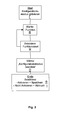
- the button 26 must now be pressed until the aforementioned icon for the range setting appears. Then, via the second button 28, the range, ie the desired function value, to select. For example, if two different ranges "high” and “low” are adjustable and the higher range is to be set, the key 28 is to be pressed as often as, for example, the symbol appears.
- a further function to be configured can now be selected by pressing the key 26 or the configuration mode can be ended.
- a termination occurs in that with the first button 26, the function "exit configuration", which is displayed for example by the symbol is selected and then selected with the second button 28, whether the entered configuration is saved and the configuration mode is to be left or whether the entered configuration should not be saved and exit the configuration mode.
- the second button 28 first to select whether to be saved or not, what the symbols and is shown, Then, by pressing the button 28 twice, the selected function is executed and the configuration mode is exited.
- a special feature is the design of the control and evaluation, so that a fail-safe input is guaranteed. This ensures that For example, a permanent pressing a button or a wrong Keystroke sequence does not cause an unwanted configuration is set.
Landscapes
- Engineering & Computer Science (AREA)
- General Engineering & Computer Science (AREA)
- Mechanical Engineering (AREA)
- Geophysics And Detection Of Objects (AREA)
- Train Traffic Observation, Control, And Security (AREA)
- Liquid Crystal (AREA)
- Eye Examination Apparatus (AREA)
- Non-Portable Lighting Devices Or Systems Thereof (AREA)
Abstract
Description
- ob eine Schützkontrolle aktiv oder inaktiv sein soll,
- ob eine Wiederanlaufsperre aktiv oder inaktiv sein soll,
- ob eine hohe oder niedrige Reichweite eingestellt werden soll,
- welches Signal an einem Diagnoseausgang anliegen soll,
- welche einer vorgegebenen Auswahl von Muting-Zeiten eingestellt werden soll.
- Fig. 1
- eine schematische Darstellung eines erfindungsgemäßen Lichtgitters;
- Fig. 2
- eine schematische Darstellung von Eingabe- und Anzeigeelementen von Konfigurationsmitteln einer Lichtempfangsleiste des Lichtgitters aus Fig. 1;
- Fig. 3
- ein Ablaufdiagramm einer Konfigurierung.
- eine Aktivierung oder Deaktivierung einer Schützkontrolle,
- eine Aktivierung oder Deaktivierung einer Wiederanlaufsperre,
- eine hohe oder niedrige Reichweite,
- welches Signal an einem Diagnoseausgang anliegen soll,
- welche einer vorgegebenen Auswahl von Muting-Zeiten eingestellt werden soll.


Dann wird durch zweimaliges Betätigen des Tasters 28 die selektierte Funktion ausgeführt und der Konfigurationsmodus verlassen.
Claims (7)
- Sicherheits-Lichtgitter zur Überwachung eines Schutzfeldes mit einer Lichtsendeleiste (12), die eine Reihe nebeneinander angeordneter Lichtsender (14) aufweist und einer Lichtempfangsleiste (16), die den Lichtsendern (14) entsprechende ebenfalls nebeneinander angeordnete Lichtempfänger (18) aufweist, so dass eine Vielzahl zueinander paralleler und das Schutzfeld (21) bildender Lichtschranken (20) gebildet sind, mit wenigstens einer Steuer- und Auswerteeinheit (24), die die einzelnen Lichtschranken steuert und auswertet, so dass bei Unterbrechung einer oder mehrerer Lichtschranken (20) durch ein Objekt ein Warnsignal ableitbar ist und mit Konfigurationsmitteln zum Konfigurieren des Lichtgitters (10), dadurch gekennzeichnet, dass die Konfigurationsmittel gebildet sind durch zwei Eingabeelemente (26 und 28) und wenigstens ein Anzeigeelement (30).
- Lichtgitter nach Anspruch 1, dadurch gekennzeichnet, dass die Steuer- und Auswerteeinheit (24) derart ausgelegt ist, dass die Eingabe von Konfigurationsdaten über die Eingabeelemente (26, 28) fehlersicher erfolgt.
- Lichtgitter nach einem der vorhergehenden Ansprüche, dadurch gekennzeichnet, dass die zwei Eingabeelemente als Taster (26 und 28) ausgebildet sind.
- Lichtgitter nach einem der vorhergehenden Ansprüche, dadurch gekennzeichnet, dass das Anzeigeelement eine Sieben-Segment-Anzeige (30) ist.
- Lichtgitter nach einem der vorhergehenden Ansprüche, dadurch gekennzeichnet, dass die Konfigurationsmittel in die Lichtempfangsleiste (16) integriert sind.
- Lichtgitter nach einem der vorhergehenden Ansprüche, dadurch gekennzeichnet, dass eines der Eingabeelemente (26) zum Wählen einer Funktion und das andere zur Selektion eines Funktionswertes ausgelegt ist.
- Lichtgitter nach einem der vorhergehenden Ansprüche, dadurch gekennzeichnet, dass zum Aktivieren eines Konfigurationsmodus beide Eingabeelemente (26 und 28) gleichzeitig betätigbar sind.
Applications Claiming Priority (2)
| Application Number | Priority Date | Filing Date | Title |
|---|---|---|---|
| DE20317976U DE20317976U1 (de) | 2003-11-20 | 2003-11-20 | Sicherheits-Lichtgitter |
| DE20317976U | 2003-11-20 |
Publications (2)
| Publication Number | Publication Date |
|---|---|
| EP1533630A1 true EP1533630A1 (de) | 2005-05-25 |
| EP1533630B1 EP1533630B1 (de) | 2006-09-20 |
Family
ID=31725268
Family Applications (1)
| Application Number | Title | Priority Date | Filing Date |
|---|---|---|---|
| EP04023321A Expired - Lifetime EP1533630B1 (de) | 2003-11-20 | 2004-09-30 | Sicherheits-Lichtgitter |
Country Status (4)
| Country | Link |
|---|---|
| US (1) | US7262403B2 (de) |
| EP (1) | EP1533630B1 (de) |
| AT (1) | ATE340366T1 (de) |
| DE (2) | DE20317976U1 (de) |
Families Citing this family (11)
| Publication number | Priority date | Publication date | Assignee | Title |
|---|---|---|---|---|
| DE102005003254B4 (de) * | 2005-01-24 | 2007-10-04 | Sick Ag | Optoelektronischer Sensor und Konfigurationsverfahren |
| JP2007223171A (ja) * | 2006-02-23 | 2007-09-06 | Mitsubishi Heavy Ind Ltd | 印刷機および印刷機の排紙装置 |
| DE102007044680B4 (de) | 2007-09-19 | 2013-01-03 | Sick Ag | Sicherheits-Lichtgitter |
| DE102007044679B3 (de) * | 2007-09-19 | 2008-11-27 | Sick Ag | Konfigurationsmittel für Sicherheits-Lichtgitter |
| US7810697B2 (en) * | 2008-08-22 | 2010-10-12 | Honda Motor Co., Ltd. | Turntable welding system with light curtain protection |
| DE202009000776U1 (de) | 2009-01-21 | 2009-06-25 | Sick Ag | Sicherheits-Lichtgitter |
| FR2951264B1 (fr) | 2009-10-12 | 2014-04-11 | Schneider Electric Ind Sas | Dispositif de detection configurable |
| CN102059580A (zh) * | 2010-11-19 | 2011-05-18 | 上海中护电子有限公司 | 带ccd辅助检测的机床安全控制系统及其方法 |
| US8881629B2 (en) * | 2012-06-12 | 2014-11-11 | Graham Packaging Company, L.P. | Continuous motion de-flash trimming machine |
| DE102015113366B3 (de) * | 2015-08-13 | 2016-10-13 | Sick Ag | Lichtgitter und Verfahren zum Rücksetzen einer Konfiguration |
| IT201700109596A1 (it) | 2017-09-29 | 2019-03-29 | Omron Tateisi Electronics Co | Metodo per il funzionamento di una barriera di sicurezza e barriera di sicurezza. |
Citations (6)
| Publication number | Priority date | Publication date | Assignee | Title |
|---|---|---|---|---|
| DE2343096A1 (de) * | 1973-08-27 | 1975-03-13 | Wolfgang Beer | Sicherungsvorrichtung, insbesondere fuer werkzeugmaschinen, mit einer lichtschranke |
| JPS56114780A (en) * | 1980-02-16 | 1981-09-09 | Matsushita Electric Works Ltd | Detector for number of passing bodies |
| EP0605252A1 (de) * | 1992-12-30 | 1994-07-06 | Allen-Bradley Company, Inc. | Photoelektrische Steuerungseinheit |
| FR2757980A1 (fr) * | 1996-12-26 | 1998-07-03 | Sarl Scmd | Dispositif electrosensible de controle d'acces |
| EP1116963A2 (de) * | 2000-01-14 | 2001-07-18 | Keyence Corporation | Photoelektrischer Schalter |
| EP1331433A2 (de) * | 2002-01-25 | 2003-07-30 | Keyence Corporation | Photoelektrische, optische Mehrwegsicherheitsvorrichtung |
Family Cites Families (9)
| Publication number | Priority date | Publication date | Assignee | Title |
|---|---|---|---|---|
| JPH0690900B2 (ja) * | 1988-11-14 | 1994-11-14 | 株式会社キーエンス | 多光軸光電スイッチ |
| DE3919167C1 (en) | 1989-06-12 | 1990-09-13 | Volker Von 6110 Dieburg De Kuczkowski | Security indicating device, e.g. for storage room - has sensors at opposite ends of passageways to determine presence of vehicle or person, and activates alarm and lamp upon object device |
| DE19827692C2 (de) | 1998-06-22 | 2001-06-13 | Hoermann Kg Antriebstechnik | Codierschaltung sowie Verwendung derselben in einer Betätigungs- oder Steuereinrichtung für ein signalbetätigbares Schließsystem |
| DE10046863C1 (de) | 2000-09-20 | 2002-01-10 | Leuze Lumiflex Gmbh & Co | Schnittstelle für Lichtschrankenanordnungen |
| DE10108962A1 (de) * | 2001-02-20 | 2002-09-12 | Pilz Gmbh & Co | Verfahren und Vorrichtung zum Programmieren einer Sicherheitssteuerung |
| JP3854512B2 (ja) * | 2002-01-25 | 2006-12-06 | 株式会社キーエンス | 多光軸光電式安全装置用の表示モニタ |
| DE10216123B4 (de) | 2002-04-12 | 2008-04-10 | Sick Ag | Überwachungsvorrichtung |
| DE10216122A1 (de) * | 2002-04-12 | 2003-10-30 | Sick Ag | Objekterfassung |
| DE10233258B4 (de) * | 2002-07-23 | 2006-07-13 | Leuze Lumiflex Gmbh + Co. Kg | Lichtgitter |
-
2003
- 2003-11-20 DE DE20317976U patent/DE20317976U1/de not_active Expired - Lifetime
-
2004
- 2004-09-30 EP EP04023321A patent/EP1533630B1/de not_active Expired - Lifetime
- 2004-09-30 DE DE502004001527T patent/DE502004001527D1/de not_active Expired - Lifetime
- 2004-09-30 AT AT04023321T patent/ATE340366T1/de not_active IP Right Cessation
- 2004-11-10 US US10/985,294 patent/US7262403B2/en not_active Expired - Fee Related
Patent Citations (6)
| Publication number | Priority date | Publication date | Assignee | Title |
|---|---|---|---|---|
| DE2343096A1 (de) * | 1973-08-27 | 1975-03-13 | Wolfgang Beer | Sicherungsvorrichtung, insbesondere fuer werkzeugmaschinen, mit einer lichtschranke |
| JPS56114780A (en) * | 1980-02-16 | 1981-09-09 | Matsushita Electric Works Ltd | Detector for number of passing bodies |
| EP0605252A1 (de) * | 1992-12-30 | 1994-07-06 | Allen-Bradley Company, Inc. | Photoelektrische Steuerungseinheit |
| FR2757980A1 (fr) * | 1996-12-26 | 1998-07-03 | Sarl Scmd | Dispositif electrosensible de controle d'acces |
| EP1116963A2 (de) * | 2000-01-14 | 2001-07-18 | Keyence Corporation | Photoelektrischer Schalter |
| EP1331433A2 (de) * | 2002-01-25 | 2003-07-30 | Keyence Corporation | Photoelektrische, optische Mehrwegsicherheitsvorrichtung |
Non-Patent Citations (1)
| Title |
|---|
| PATENT ABSTRACTS OF JAPAN vol. 0051, no. 91 (P - 092) 5 December 1981 (1981-12-05) * |
Also Published As
| Publication number | Publication date |
|---|---|
| DE20317976U1 (de) | 2004-02-12 |
| EP1533630B1 (de) | 2006-09-20 |
| US7262403B2 (en) | 2007-08-28 |
| DE502004001527D1 (de) | 2006-11-02 |
| ATE340366T1 (de) | 2006-10-15 |
| US20050109920A1 (en) | 2005-05-26 |
Similar Documents
| Publication | Publication Date | Title |
|---|---|---|
| EP1933174B1 (de) | Lichtgitter | |
| EP1946154B1 (de) | Verfahren und bedieneinheit zum konfigurieren und überwachen einer einrichtung mit funktionaler sicherheit | |
| EP3961317A2 (de) | Verfahren zur konfiguration einer modularen sicherheitsschaltvorrichtung | |
| DE102015210657A1 (de) | Verfahren zur Erkennung einer Stellbewegung eines auf einer Anzeigefläche befindlichen Stellelementes in einem Kraftfahrzeug und Vorrichtung zur Durchführung des Verfahrens | |
| EP1533630B1 (de) | Sicherheits-Lichtgitter | |
| DE102007044680B4 (de) | Sicherheits-Lichtgitter | |
| DE10329881A1 (de) | Lichtgitter | |
| EP3064050B1 (de) | Steuerungssystem für ein landwirtschaftliches arbeitsgerät | |
| WO2014206886A1 (de) | Verfahren zur synchronisation eines lichtgitters | |
| EP1437542B1 (de) | Lichtgitter und Verfahren zu dessen Justierung | |
| DE102006012537A1 (de) | Lichtgitter | |
| DE102007044679B3 (de) | Konfigurationsmittel für Sicherheits-Lichtgitter | |
| DE2343096A1 (de) | Sicherungsvorrichtung, insbesondere fuer werkzeugmaschinen, mit einer lichtschranke | |
| DE202009000776U1 (de) | Sicherheits-Lichtgitter | |
| EP3594553A1 (de) | Vorrichtung zur überwachung eines gefahrenbereichs | |
| DE102009031226B4 (de) | Sicherheitslichtgitter | |
| DE102008022791C5 (de) | Lichtvorhang | |
| DE202015100154U1 (de) | Sicherheitslichtgitter | |
| DE102008060117A1 (de) | Maschine mit Bediengerät für sicherheitsrelevante Funktionen | |
| DE10359561A1 (de) | Bedienelement für ein Haushaltsgerät | |
| DE202007014653U1 (de) | Konfigurationsmittel für Sicherheits-Lichtgitter | |
| DE2356107C3 (de) | Mit logischen Signalen arbeitende Ablaufsteuerung | |
| EP2487512B1 (de) | Verfahren zum Betrieb eines Lichtgitters und Lichtgitter | |
| EP3726313B1 (de) | Sicherheitsschaltvorrichtung | |
| DE102015113366B3 (de) | Lichtgitter und Verfahren zum Rücksetzen einer Konfiguration |
Legal Events
| Date | Code | Title | Description |
|---|---|---|---|
| PUAI | Public reference made under article 153(3) epc to a published international application that has entered the european phase |
Free format text: ORIGINAL CODE: 0009012 |
|
| AK | Designated contracting states |
Kind code of ref document: A1 Designated state(s): AT BE BG CH CY CZ DE DK EE ES FI FR GB GR HU IE IT LI LU MC NL PL PT RO SE SI SK TR |
|
| AX | Request for extension of the european patent |
Extension state: AL HR LT LV MK |
|
| 17P | Request for examination filed |
Effective date: 20051012 |
|
| AKX | Designation fees paid |
Designated state(s): AT BE BG CH CY CZ DE DK EE ES FI FR GB GR HU IE IT LI LU MC NL PL PT RO SE SI SK TR |
|
| GRAP | Despatch of communication of intention to grant a patent |
Free format text: ORIGINAL CODE: EPIDOSNIGR1 |
|
| GRAS | Grant fee paid |
Free format text: ORIGINAL CODE: EPIDOSNIGR3 |
|
| GRAA | (expected) grant |
Free format text: ORIGINAL CODE: 0009210 |
|
| AK | Designated contracting states |
Kind code of ref document: B1 Designated state(s): AT BE BG CH CY CZ DE DK EE ES FI FR GB GR HU IE IT LI LU MC NL PL PT RO SE SI SK TR |
|
| PG25 | Lapsed in a contracting state [announced via postgrant information from national office to epo] |
Ref country code: RO Free format text: LAPSE BECAUSE OF FAILURE TO SUBMIT A TRANSLATION OF THE DESCRIPTION OR TO PAY THE FEE WITHIN THE PRESCRIBED TIME-LIMIT Effective date: 20060920 Ref country code: NL Free format text: LAPSE BECAUSE OF FAILURE TO SUBMIT A TRANSLATION OF THE DESCRIPTION OR TO PAY THE FEE WITHIN THE PRESCRIBED TIME-LIMIT Effective date: 20060920 Ref country code: IE Free format text: LAPSE BECAUSE OF FAILURE TO SUBMIT A TRANSLATION OF THE DESCRIPTION OR TO PAY THE FEE WITHIN THE PRESCRIBED TIME-LIMIT Effective date: 20060920 Ref country code: FI Free format text: LAPSE BECAUSE OF FAILURE TO SUBMIT A TRANSLATION OF THE DESCRIPTION OR TO PAY THE FEE WITHIN THE PRESCRIBED TIME-LIMIT Effective date: 20060920 Ref country code: SK Free format text: LAPSE BECAUSE OF FAILURE TO SUBMIT A TRANSLATION OF THE DESCRIPTION OR TO PAY THE FEE WITHIN THE PRESCRIBED TIME-LIMIT Effective date: 20060920 Ref country code: SI Free format text: LAPSE BECAUSE OF FAILURE TO SUBMIT A TRANSLATION OF THE DESCRIPTION OR TO PAY THE FEE WITHIN THE PRESCRIBED TIME-LIMIT Effective date: 20060920 Ref country code: CZ Free format text: LAPSE BECAUSE OF FAILURE TO SUBMIT A TRANSLATION OF THE DESCRIPTION OR TO PAY THE FEE WITHIN THE PRESCRIBED TIME-LIMIT Effective date: 20060920 Ref country code: PL Free format text: LAPSE BECAUSE OF FAILURE TO SUBMIT A TRANSLATION OF THE DESCRIPTION OR TO PAY THE FEE WITHIN THE PRESCRIBED TIME-LIMIT Effective date: 20060920 |
|
| REG | Reference to a national code |
Ref country code: GB Ref legal event code: FG4D Free format text: NOT ENGLISH |
|
| PG25 | Lapsed in a contracting state [announced via postgrant information from national office to epo] |
Ref country code: BE Free format text: LAPSE BECAUSE OF NON-PAYMENT OF DUE FEES Effective date: 20060930 Ref country code: MC Free format text: LAPSE BECAUSE OF NON-PAYMENT OF DUE FEES Effective date: 20060930 |
|
| GBT | Gb: translation of ep patent filed (gb section 77(6)(a)/1977) |
Effective date: 20060920 |
|
| REG | Reference to a national code |
Ref country code: CH Ref legal event code: EP |
|
| REG | Reference to a national code |
Ref country code: IE Ref legal event code: FG4D Free format text: LANGUAGE OF EP DOCUMENT: GERMAN |
|
| REF | Corresponds to: |
Ref document number: 502004001527 Country of ref document: DE Date of ref document: 20061102 Kind code of ref document: P |
|
| PG25 | Lapsed in a contracting state [announced via postgrant information from national office to epo] |
Ref country code: DK Free format text: LAPSE BECAUSE OF FAILURE TO SUBMIT A TRANSLATION OF THE DESCRIPTION OR TO PAY THE FEE WITHIN THE PRESCRIBED TIME-LIMIT Effective date: 20061220 Ref country code: BG Free format text: LAPSE BECAUSE OF FAILURE TO SUBMIT A TRANSLATION OF THE DESCRIPTION OR TO PAY THE FEE WITHIN THE PRESCRIBED TIME-LIMIT Effective date: 20061220 Ref country code: SE Free format text: LAPSE BECAUSE OF FAILURE TO SUBMIT A TRANSLATION OF THE DESCRIPTION OR TO PAY THE FEE WITHIN THE PRESCRIBED TIME-LIMIT Effective date: 20061220 |
|
| PG25 | Lapsed in a contracting state [announced via postgrant information from national office to epo] |
Ref country code: ES Free format text: LAPSE BECAUSE OF FAILURE TO SUBMIT A TRANSLATION OF THE DESCRIPTION OR TO PAY THE FEE WITHIN THE PRESCRIBED TIME-LIMIT Effective date: 20061231 |
|
| RAP2 | Party data changed (patent owner data changed or rights of a patent transferred) |
Owner name: SICK AG |
|
| ET | Fr: translation filed | ||
| NLV1 | Nl: lapsed or annulled due to failure to fulfill the requirements of art. 29p and 29m of the patents act | ||
| PG25 | Lapsed in a contracting state [announced via postgrant information from national office to epo] |
Ref country code: PT Free format text: LAPSE BECAUSE OF FAILURE TO SUBMIT A TRANSLATION OF THE DESCRIPTION OR TO PAY THE FEE WITHIN THE PRESCRIBED TIME-LIMIT Effective date: 20070312 |
|
| REG | Reference to a national code |
Ref country code: IE Ref legal event code: FD4D |
|
| PLBE | No opposition filed within time limit |
Free format text: ORIGINAL CODE: 0009261 |
|
| STAA | Information on the status of an ep patent application or granted ep patent |
Free format text: STATUS: NO OPPOSITION FILED WITHIN TIME LIMIT |
|
| 26N | No opposition filed |
Effective date: 20070621 |
|
| PG25 | Lapsed in a contracting state [announced via postgrant information from national office to epo] |
Ref country code: AT Free format text: LAPSE BECAUSE OF NON-PAYMENT OF DUE FEES Effective date: 20060930 |
|
| BERE | Be: lapsed |
Owner name: SICK A.G. Effective date: 20060930 |
|
| PG25 | Lapsed in a contracting state [announced via postgrant information from national office to epo] |
Ref country code: GR Free format text: LAPSE BECAUSE OF FAILURE TO SUBMIT A TRANSLATION OF THE DESCRIPTION OR TO PAY THE FEE WITHIN THE PRESCRIBED TIME-LIMIT Effective date: 20061221 |
|
| PG25 | Lapsed in a contracting state [announced via postgrant information from national office to epo] |
Ref country code: EE Free format text: LAPSE BECAUSE OF FAILURE TO SUBMIT A TRANSLATION OF THE DESCRIPTION OR TO PAY THE FEE WITHIN THE PRESCRIBED TIME-LIMIT Effective date: 20060920 |
|
| PG25 | Lapsed in a contracting state [announced via postgrant information from national office to epo] |
Ref country code: TR Free format text: LAPSE BECAUSE OF FAILURE TO SUBMIT A TRANSLATION OF THE DESCRIPTION OR TO PAY THE FEE WITHIN THE PRESCRIBED TIME-LIMIT Effective date: 20060920 Ref country code: LU Free format text: LAPSE BECAUSE OF NON-PAYMENT OF DUE FEES Effective date: 20060930 Ref country code: HU Free format text: LAPSE BECAUSE OF FAILURE TO SUBMIT A TRANSLATION OF THE DESCRIPTION OR TO PAY THE FEE WITHIN THE PRESCRIBED TIME-LIMIT Effective date: 20070321 |
|
| PG25 | Lapsed in a contracting state [announced via postgrant information from national office to epo] |
Ref country code: CY Free format text: LAPSE BECAUSE OF FAILURE TO SUBMIT A TRANSLATION OF THE DESCRIPTION OR TO PAY THE FEE WITHIN THE PRESCRIBED TIME-LIMIT Effective date: 20060920 |
|
| REG | Reference to a national code |
Ref country code: CH Ref legal event code: PL |
|
| PG25 | Lapsed in a contracting state [announced via postgrant information from national office to epo] |
Ref country code: LI Free format text: LAPSE BECAUSE OF NON-PAYMENT OF DUE FEES Effective date: 20060930 Ref country code: CH Free format text: LAPSE BECAUSE OF NON-PAYMENT OF DUE FEES Effective date: 20060930 |
|
| PG25 | Lapsed in a contracting state [announced via postgrant information from national office to epo] |
Ref country code: LI Free format text: LAPSE BECAUSE OF NON-PAYMENT OF DUE FEES Effective date: 20080930 Ref country code: CH Free format text: LAPSE BECAUSE OF NON-PAYMENT OF DUE FEES Effective date: 20080930 |
|
| PGFP | Annual fee paid to national office [announced via postgrant information from national office to epo] |
Ref country code: GB Payment date: 20130920 Year of fee payment: 10 |
|
| GBPC | Gb: european patent ceased through non-payment of renewal fee |
Effective date: 20140930 |
|
| PG25 | Lapsed in a contracting state [announced via postgrant information from national office to epo] |
Ref country code: GB Free format text: LAPSE BECAUSE OF NON-PAYMENT OF DUE FEES Effective date: 20140930 |
|
| REG | Reference to a national code |
Ref country code: FR Ref legal event code: PLFP Year of fee payment: 12 |
|
| PGFP | Annual fee paid to national office [announced via postgrant information from national office to epo] |
Ref country code: FR Payment date: 20150923 Year of fee payment: 12 |
|
| REG | Reference to a national code |
Ref country code: FR Ref legal event code: ST Effective date: 20170531 |
|
| PG25 | Lapsed in a contracting state [announced via postgrant information from national office to epo] |
Ref country code: FR Free format text: LAPSE BECAUSE OF NON-PAYMENT OF DUE FEES Effective date: 20160930 |
|
| PGFP | Annual fee paid to national office [announced via postgrant information from national office to epo] |
Ref country code: IT Payment date: 20170926 Year of fee payment: 14 Ref country code: DE Payment date: 20170921 Year of fee payment: 14 |
|
| REG | Reference to a national code |
Ref country code: DE Ref legal event code: R119 Ref document number: 502004001527 Country of ref document: DE |
|
| PG25 | Lapsed in a contracting state [announced via postgrant information from national office to epo] |
Ref country code: IT Free format text: LAPSE BECAUSE OF NON-PAYMENT OF DUE FEES Effective date: 20180930 Ref country code: DE Free format text: LAPSE BECAUSE OF NON-PAYMENT OF DUE FEES Effective date: 20190402 |