EP1533197A1 - Seitenairbag und Faltverfahren - Google Patents
Seitenairbag und Faltverfahren Download PDFInfo
- Publication number
- EP1533197A1 EP1533197A1 EP04078144A EP04078144A EP1533197A1 EP 1533197 A1 EP1533197 A1 EP 1533197A1 EP 04078144 A EP04078144 A EP 04078144A EP 04078144 A EP04078144 A EP 04078144A EP 1533197 A1 EP1533197 A1 EP 1533197A1
- Authority
- EP
- European Patent Office
- Prior art keywords
- inflatable cushion
- folded
- securement
- vehicle
- headliner
- Prior art date
- Legal status (The legal status is an assumption and is not a legal conclusion. Google has not performed a legal analysis and makes no representation as to the accuracy of the status listed.)
- Granted
Links
- 238000000034 method Methods 0.000 title claims abstract description 17
- 230000004913 activation Effects 0.000 description 5
- 239000000463 material Substances 0.000 description 5
- JOYRKODLDBILNP-UHFFFAOYSA-N Ethyl urethane Chemical compound CCOC(N)=O JOYRKODLDBILNP-UHFFFAOYSA-N 0.000 description 2
- 239000004677 Nylon Substances 0.000 description 2
- 239000012530 fluid Substances 0.000 description 2
- 229920001778 nylon Polymers 0.000 description 2
- 230000000694 effects Effects 0.000 description 1
- 239000004744 fabric Substances 0.000 description 1
- 238000012986 modification Methods 0.000 description 1
- 230000004048 modification Effects 0.000 description 1
- 239000004033 plastic Substances 0.000 description 1
- 229920001296 polysiloxane Polymers 0.000 description 1
- 230000001681 protective effect Effects 0.000 description 1
Images


Classifications
-
- B—PERFORMING OPERATIONS; TRANSPORTING
- B60—VEHICLES IN GENERAL
- B60R—VEHICLES, VEHICLE FITTINGS, OR VEHICLE PARTS, NOT OTHERWISE PROVIDED FOR
- B60R21/00—Arrangements or fittings on vehicles for protecting or preventing injuries to occupants or pedestrians in case of accidents or other traffic risks
- B60R21/02—Occupant safety arrangements or fittings, e.g. crash pads
- B60R21/16—Inflatable occupant restraints or confinements designed to inflate upon impact or impending impact, e.g. air bags
- B60R21/23—Inflatable members
- B60R21/231—Inflatable members characterised by their shape, construction or spatial configuration
- B60R21/23138—Inflatable members characterised by their shape, construction or spatial configuration specially adapted for side protection
-
- B—PERFORMING OPERATIONS; TRANSPORTING
- B60—VEHICLES IN GENERAL
- B60R—VEHICLES, VEHICLE FITTINGS, OR VEHICLE PARTS, NOT OTHERWISE PROVIDED FOR
- B60R21/00—Arrangements or fittings on vehicles for protecting or preventing injuries to occupants or pedestrians in case of accidents or other traffic risks
- B60R21/02—Occupant safety arrangements or fittings, e.g. crash pads
- B60R21/16—Inflatable occupant restraints or confinements designed to inflate upon impact or impending impact, e.g. air bags
- B60R21/23—Inflatable members
- B60R21/237—Inflatable members characterised by the way they are folded
-
- B—PERFORMING OPERATIONS; TRANSPORTING
- B60—VEHICLES IN GENERAL
- B60R—VEHICLES, VEHICLE FITTINGS, OR VEHICLE PARTS, NOT OTHERWISE PROVIDED FOR
- B60R21/00—Arrangements or fittings on vehicles for protecting or preventing injuries to occupants or pedestrians in case of accidents or other traffic risks
- B60R21/02—Occupant safety arrangements or fittings, e.g. crash pads
- B60R21/16—Inflatable occupant restraints or confinements designed to inflate upon impact or impending impact, e.g. air bags
- B60R21/23—Inflatable members
- B60R21/231—Inflatable members characterised by their shape, construction or spatial configuration
- B60R21/232—Curtain-type airbags deploying mainly in a vertical direction from their top edge
-
- B—PERFORMING OPERATIONS; TRANSPORTING
- B60—VEHICLES IN GENERAL
- B60R—VEHICLES, VEHICLE FITTINGS, OR VEHICLE PARTS, NOT OTHERWISE PROVIDED FOR
- B60R21/00—Arrangements or fittings on vehicles for protecting or preventing injuries to occupants or pedestrians in case of accidents or other traffic risks
- B60R21/02—Occupant safety arrangements or fittings, e.g. crash pads
- B60R21/16—Inflatable occupant restraints or confinements designed to inflate upon impact or impending impact, e.g. air bags
- B60R21/23—Inflatable members
- B60R21/231—Inflatable members characterised by their shape, construction or spatial configuration
- B60R21/2334—Expansion control features
- B60R21/2338—Tethers
-
- B—PERFORMING OPERATIONS; TRANSPORTING
- B62—LAND VEHICLES FOR TRAVELLING OTHERWISE THAN ON RAILS
- B62D—MOTOR VEHICLES; TRAILERS
- B62D25/00—Superstructure or monocoque structure sub-units; Parts or details thereof not otherwise provided for
- B62D25/06—Fixed roofs
-
- B—PERFORMING OPERATIONS; TRANSPORTING
- B60—VEHICLES IN GENERAL
- B60R—VEHICLES, VEHICLE FITTINGS, OR VEHICLE PARTS, NOT OTHERWISE PROVIDED FOR
- B60R21/00—Arrangements or fittings on vehicles for protecting or preventing injuries to occupants or pedestrians in case of accidents or other traffic risks
- B60R21/02—Occupant safety arrangements or fittings, e.g. crash pads
- B60R21/16—Inflatable occupant restraints or confinements designed to inflate upon impact or impending impact, e.g. air bags
- B60R21/23—Inflatable members
- B60R21/231—Inflatable members characterised by their shape, construction or spatial configuration
- B60R21/2334—Expansion control features
- B60R21/2338—Tethers
- B60R2021/23386—External tether means
-
- B—PERFORMING OPERATIONS; TRANSPORTING
- B60—VEHICLES IN GENERAL
- B60R—VEHICLES, VEHICLE FITTINGS, OR VEHICLE PARTS, NOT OTHERWISE PROVIDED FOR
- B60R21/00—Arrangements or fittings on vehicles for protecting or preventing injuries to occupants or pedestrians in case of accidents or other traffic risks
- B60R21/02—Occupant safety arrangements or fittings, e.g. crash pads
- B60R21/16—Inflatable occupant restraints or confinements designed to inflate upon impact or impending impact, e.g. air bags
- B60R21/23—Inflatable members
- B60R21/235—Inflatable members characterised by their material
- B60R2021/23504—Inflatable members characterised by their material characterised by material
- B60R2021/23509—Fabric
- B60R2021/23514—Fabric coated fabric
-
- B—PERFORMING OPERATIONS; TRANSPORTING
- B60—VEHICLES IN GENERAL
- B60R—VEHICLES, VEHICLE FITTINGS, OR VEHICLE PARTS, NOT OTHERWISE PROVIDED FOR
- B60R21/00—Arrangements or fittings on vehicles for protecting or preventing injuries to occupants or pedestrians in case of accidents or other traffic risks
- B60R21/02—Occupant safety arrangements or fittings, e.g. crash pads
- B60R21/16—Inflatable occupant restraints or confinements designed to inflate upon impact or impending impact, e.g. air bags
- B60R21/20—Arrangements for storing inflatable members in their non-use or deflated condition; Arrangement or mounting of air bag modules or components
- B60R21/213—Arrangements for storing inflatable members in their non-use or deflated condition; Arrangement or mounting of air bag modules or components in vehicle roof frames or pillars
Definitions
- the present application relates to side airbag devices and more particularly the present application relates to an apparatus and method for configuring the deployment characteristics of a side airbag device.
- Vehicles are supplied with side airbag devices.
- the device is located along a side of the vehicle and deploys an inflatable curtain in accordance with a predetermined activation occurrence.
- the side impact air bags are often mounted in close proximity to the vehicle's roof rail, doorframe or center pillars, or in some instances within the side door. Accordingly, the space or housing for the un-inflated airbag is compact and extends or traverses along the window area or frame, as the airbag cannot be installed in the areas comprising the window.
- the presence of the side airbag device is not observable to occupants when it is in its un-deployed state.
- the top edge portion When the air bag or inflatable cushion is mounted to the vehicle the top edge portion is fixed and a lower edge portion which defines the bottom periphery of the airbag deploys out of the storage location positioned in close proximity to the roof rail. Accordingly, it is desirable to provide a folded side airbag wherein the lower edge portion is the first portion of the airbag to deploy out of its housing during an activation event.
- This disclosure relates to a method and apparatus for providing a side airbag device having an inflatable cushion.
- the inflatable cushion is folded and positioned in such a manner that the portion of the inflatable cushion comprising the furthest point of deployment from a point of securement of the inflatable cushion to the vehicle is deployed around a deployable structure housing the un-inflated cushion first.
- a method and apparatus for providing a side airbag device for use in a vehicle comprising: an inflatable cushion for deployment from an unexpanded state to an expanded state.
- the inflatable cushion is positioned behind a headliner of the vehicle in an un-inflated state and the inflatable cushion is configured to traverse a side of the vehicle when it is inflated.
- the inflatable cushion also comprising a deploying edge that defines a portion of a periphery of the inflated cushion, wherein the inflatable cushion is folded in a manner that causes the deploying edge to deploy as a first leading edge as said inflatable cushion is inflated to an expanded state by an inflator wherein the deploying edge is the first portion of the inflatable cushion to expand around the headliner.
- a method for folding an inflatable cushion of a side airbag device comprising: providing a securement end of the inflatable cushion; creating a first fold at a first position away from the securement end, the first fold and the securement end defining one side of the folded inflatable cushion; positioning a traversing portion of the inflatable cushion away from the first fold, the traversing portion defining another side of the folded inflatable cushion; creating a plurality of folds from the traversing portion back towards the first fold; positioning an end portion of the inflatable cushion about the plurality of folds, the end portion defining another two sides of the folded inflatable cushion, wherein the end portion is the first portion of the inflatable cushion to deploy when the inflatable cushion is inflated.
- a side airbag device for use in a vehicle having a forward end, a rearward end and a pair of sides disposed therebetween, comprising: an inflatable cushion for deployment from an unexpanded state to an expanded state, the inflatable cushion being configured to traverse a portion one of the pair of sides of the vehicle in the expanded state, the inflatable cushion comprising an inflation opening, a fixed portion and a deploying edge, the deploying edge comprising a majority of a periphery of the inflatable cushion; an inflator for inflating the inflatable cushion; wherein the inflatable cushion is folded in a manner that causes the deploying edge to deploy as a first leading edge as the inflatable cushion is inflated to the expanded state by the inflator.
- This disclosure relates to an airbag device wherein the inflatable cushion is stored in such a manner that the first portion to deploy from the storage location of the inflatable cushion is the lower leading edge of the same. More particularly, the inflatable cushion is folded in such a manner that the lower leading edge of the deployed cushion is deployed first from a storage location or housing area of the body inflated inflatable cushion.
- Airbag 10 is manufactured and constructed in accordance with exemplary embodiments of the present invention.
- Figure 1 illustrates the airbag mounted to a vehicle 12 in a stored or non-deployed state.
- Vehicle 12 comprises a front pillar 14, a rear pillar 16 and if the vehicle has more than one door per side, a center pillar 18.
- Airbag 10 is stored and mounted to or proximate to the vehicle roof rail 20.
- a first tether or connecting means 22 connects a front portion 24 of the air bag to the front pillar and a second tether or connecting means 26 connects a rear portion 28 of the air bag to the rear pillar.
- the connecting means 22 and 26 are provided as examples and the present invention is not intended to be limited by the same.
- the rear portion of the air bag is in fluid communication with a gas generator or inflator 30 positioned to provide an inflation gas to inflate airbag 10.
- a gas generator or inflator 30 positioned to provide an inflation gas to inflate airbag 10.
- the positioning of the inflator may be located in other positions than those illustrated in the drawings.
- the inflator may be located in a forward vehicle position.
- the presented location is provided as an example and the present invention is not intended to be limited by the same.
- the inflator may be remotely located and a conduit or other fluid providing means is used to supply the inflating gas from the inflator to the inflatable cushion.
- FIGS 2 and 3 illustrate airbag 10 in an inflated or deployed state.
- airbag 10 comprises a deploying edge 32, which comprises the bottom portion of the airbag that traverses across the window openings or window frames of the vehicle.
- Airbag 10 also comprises a forward edge 34, a rearward edge 36 and a fixed edge 38.
- Fixed edge 38 represents the portion of the airbag that remains in substantially the same position regardless of whether the airbag 10 is deployed or not.
- Figures 2 and 3 also illustrate different types of airbags or inflatable cushion arrangements e.g., internal cavities, tethers or seams positioned to provide desired inflation characteristics or effects.
- the configuration of airbag 10 may vary and the illustrations in Figures 2 and 3 are provided as examples and the present invention is not intended to be limited to the specific configurations provided in the figures as they are considered ancillary to the present invention.
- the present invention is contemplated for use with other vehicle configurations than those illustrated in Figures 1-3.
- the vehicle may be include three rows of seats such vehicles include but are not limited to sports utility vehicles, station wagons, vans or minivans.
- the vehicle may comprise only a single row of seats such vehicles include but are not limited to sports coups.
- the tethers or connecting means secure the inflatable cushion between the A-pillar 14 and the C-pillar 16 spanning the B-pillar 18.
- the inflatable cushion may be made to extend more rearwardly and is secured to a D-pillar of a vehicle having a longer body frame.
- the inflatable cushion may be configured for deployment only in the forward compartment of the vehicle wherein the inflatable cushion is connected to only the A-pillar and B-pillars.
- a single inflatable cushion is configured to traverse between both the front and rear passenger compartments. Accordingly, the inflatable cushion is connected at one end to the A-pillar 14 and the C-pillar 16. It is, of course, understood that these connection points may vary with the configuration of the inflatable cushion.
- the inflatable cushion may be made of any suitable air bag material for holding gas.
- the inflatable cushion comprises two sheets of woven nylon fabric lined with urethane or other substantially impervious material such as silicone. The two urethane coated nylon sheets are secured to one another along an outer periphery thereof to define the overall air bag shape.
- the inflatable cushion Prior to deployment, the inflatable cushion is stored in a compartment mounted to the roof rail 24 or proximate to the roof rail as shown in Figure 1.
- the un-inflated airbag is folded into a configuration which allows it to occupy a small discrete area within the vehicle interior.
- the inflatable cushion is folded by a machine in order to provide the configurations disclosed herein. It is also possible to fold the inflatable cushion by hand.
- the tethers or connecting means are also stored in compartments of corresponding pillars 14 and 16.
- the inflatable cushion is inflated by gas from inflator 30.
- inflator 30 will receive an inflation or deployment signal that causes inflator 30 to generate an inflation gas for inflating the inflatable cushion.
- the deployment signal is generated by a controller, such as a microcontroller of a sensing and diagnostic module configured for use with the airbag module.
- the sensing and diagnostic module receives a plurality of signals from appropriate sensing devices (e.g., door mounted accelerometers), and will generate a deployment signal if a predetermined activation event has been sensed.
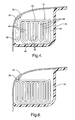
- FIG. 4 a cross sectional view of airbag 10 secured in an un-inflated configuration is illustrated.
- fixed edge 38 of airbag 10 is secured to a portion of roof rail 20.
- airbag 10 is received within an area defined by roof rail 20 and headliner 40.
- headliner 40 comprises a portion of the interior trim of the vehicle and is configurable to be secured about airbag 10 in a detachable manner.
- headline 40 provides an aesthetically pleasing appearance for the vehicle interior.
- headliner 40 is constructed out of material capable of being deflected or separated in response to the inflation pressure of airbag 10 during deployment. It is, of course, understood that headliner 40 may have other configurations and/or tear seams or grooves to facilitate movement of a portion of the headliner when the side airbag deploys.
- headliner 40 may be configured to and a series of curves which allow the headliner to be disposed around the folded inflatable cushion when it is secured to the vehicle roof rail. Moreover, the curves may assist in the deployment of the inflatable cushion by allowing the headliner to fold at certain points defined by the curves of the headliner.
- airbag or inflatable cushion 10 is positioned behind headliner 40 in the following configuration.
- the inflatable cushion is folded in accordance with exemplary embodiment of the present invention, which will be discussed below when referring to the cross sectional view of Figure 4.
- fixed edge 38 is secured to the roof rail by a plurality of bolts, screws or other adequate type of securing means.
- Fixed edge 32 also comprises a plurality of openings for use with the plurality of securing means for securing fixed edge 32 to the vehicle roof rail.
- the folded inflatable cushion travels downwardly from fixed edge 38 until a first fold 42 is made.
- these portions of the inflatable cushion are located at the outboard side of the vehicle (e.g., Figure 4).
- the folded cushion is then arranged to have an upper traversing portion 44 that traverses towards an inboard side of the vehicle.
- the traversing portion extends over one side of a plurality of folds or pleats 46 of the airbag which are folded over each other back towards the outboard side of the vehicle or towards first fold 42.
- the cushion is then folded to have a lower traversing portion 48 that traverses back towards the inboard side of the vehicle.
- an end portion or belt line portion 50 corresponding to deploying edge 32 is folded over the inboard side of the folded cushion.
- end portion 50 is positioned to be the first portion of the side airbag which contacts headliner 40 and therefore end portion 50 is the first portion that travels around headliner 40 as the cushion is inflated by the inflator.
- end portion 50 corresponding to deploying edge 32 to deploy first out of the receiving area defined by roof rail 20 and headliner 40.
- the initial deployment configuration is illustrated in Figure 5 wherein a portion of inflation gas has been supplied to inflatable cushion 10 during the initial stages of inflation and end portion 50 is the first portion to deploy out of headliner 40. Then each one of the plurality of folds 46 will deploy downwardly as the inflatable cushion begins to assume the shapes illustrated in Figures 2 and 3. It is noted that the specific final configuration or location of end portion 50 may vary from the specific location illustrated in Figures 4 and 6 as long as end portion 50 contacts the headliner first during inflation and is the first portion to deploy around headliner 40.
- the inflatable cushion is folded first and then secured to the vehicle (e.g., the secured to the roof rail and securement of the inflator and connecting tethers 22 and 26). Afterwards, the headliner is secured to enclose the folded airbag in a cavity defined by the headliner and the roof rail of the vehicle.
- a layer of plastic or other protective material may be disposed between relevant portions of airbag 10 and roof rail 20.
- a plurality of retaining clips 60 may be disposed along the length of airbag 10 in order to assist in the securement of the same to the vehicle roof rail.
- the retaining clips would depend away from the roof rail and be configured to wrap around the folded inflatable cushion. During deployment the retaining clips would bend out of the way as the cushion is inflated.
- time to position e.g., time from the initial sensing of impact or deceleration, activation of inflator and inflation of the airbag having the folded configuration of Figure 4 wherein the leading edge is positioned at the belt line or lowest deployment position of the inflated airbag is function of the inflating cushion from its housing or cavity wherein it is installed in an un-inflated state. It is, of course, understood that the various configurations of the airbag module and the vehicle in which it is installed may affect this time.
- fixed edge portion 38 extends directly from traversing portion 44 and first fold 42 is eliminated.
Landscapes
- Engineering & Computer Science (AREA)
- Mechanical Engineering (AREA)
- Chemical & Material Sciences (AREA)
- Combustion & Propulsion (AREA)
- Transportation (AREA)
- Air Bags (AREA)
Applications Claiming Priority (2)
| Application Number | Priority Date | Filing Date | Title |
|---|---|---|---|
| US718453 | 2003-11-20 | ||
| US10/718,453 US7243940B2 (en) | 2003-11-20 | 2003-11-20 | Side airbag and method of folding |
Publications (2)
| Publication Number | Publication Date |
|---|---|
| EP1533197A1 true EP1533197A1 (de) | 2005-05-25 |
| EP1533197B1 EP1533197B1 (de) | 2006-11-29 |
Family
ID=34435785
Family Applications (1)
| Application Number | Title | Priority Date | Filing Date |
|---|---|---|---|
| EP04078144A Expired - Lifetime EP1533197B1 (de) | 2003-11-20 | 2004-11-17 | Seitenairbag und Faltverfahren |
Country Status (6)
| Country | Link |
|---|---|
| US (3) | US7243940B2 (de) |
| EP (1) | EP1533197B1 (de) |
| JP (1) | JP2005193887A (de) |
| KR (1) | KR100650634B1 (de) |
| AT (1) | ATE346771T1 (de) |
| DE (1) | DE602004003454T2 (de) |
Cited By (1)
| Publication number | Priority date | Publication date | Assignee | Title |
|---|---|---|---|---|
| EP3412517A4 (de) * | 2016-03-29 | 2019-07-03 | Autoliv Development AB | Airbag und airbaganordnung |
Families Citing this family (10)
| Publication number | Priority date | Publication date | Assignee | Title |
|---|---|---|---|---|
| JP4391308B2 (ja) * | 2004-04-28 | 2009-12-24 | タカタ株式会社 | エアバッグ装置 |
| US7513523B2 (en) * | 2005-08-18 | 2009-04-07 | Trw Vehicle Safety Systems Inc. | Inflatable curtain with different size panels |
| US8002311B2 (en) * | 2006-10-26 | 2011-08-23 | Tk Holdings Inc. | Airbag with sections of different deployment lengths |
| JP2008132945A (ja) * | 2006-11-29 | 2008-06-12 | Takata Corp | エアバッグ装置 |
| DE102007022152B4 (de) * | 2007-05-11 | 2015-04-09 | Autoliv Development Ab | Seitenairbag mit wenigstens einem vorfixierten Haltefortsatz |
| US8025308B2 (en) * | 2007-10-09 | 2011-09-27 | Tk Holdings Inc. | Curtain airbag |
| DE102007048951A1 (de) * | 2007-10-12 | 2009-04-16 | Dr. Ing. H.C. F. Porsche Aktiengesellschaft | Fahrzeuginsassen-Schutzeinrichtung |
| WO2009137722A1 (en) * | 2008-05-07 | 2009-11-12 | Nanocomp Technologies, Inc. | Carbon nanotube-based coaxial electrical cables and wiring harness |
| KR102002841B1 (ko) * | 2012-12-27 | 2019-07-26 | 현대모비스 주식회사 | 커튼 에어백 쿠션 |
| KR102792229B1 (ko) | 2019-10-15 | 2025-04-04 | 현대자동차주식회사 | 차량용 커튼 에어백 |
Citations (3)
| Publication number | Priority date | Publication date | Assignee | Title |
|---|---|---|---|---|
| EP0855315A1 (de) * | 1997-01-24 | 1998-07-29 | HS Technik und Design Technische Entwicklungen GmbH | Airbagvorrichtung |
| US20020096864A1 (en) * | 1998-08-03 | 2002-07-25 | Toyota Jidosha Kabushiki Kaisha | Airbag apparatus for head-protecting |
| EP1342629A2 (de) * | 2002-03-05 | 2003-09-10 | Delphi Technologies, Inc. | Seitenairbag-Vorrichtung |
Family Cites Families (15)
| Publication number | Priority date | Publication date | Assignee | Title |
|---|---|---|---|---|
| US2039335A (en) * | 1931-04-20 | 1936-05-05 | Nall Torney Otto | Method and apparatus for folding sheets |
| US2902535A (en) * | 1956-10-29 | 1959-09-01 | Gen Electric | Prefolded cord and method of making same |
| US3038718A (en) * | 1961-01-19 | 1962-06-12 | Maurice M Balsam | Sheet folding machine |
| US5493846A (en) * | 1993-04-07 | 1996-02-27 | Automated Solutions Inc. | Bag folding system |
| US6073961A (en) * | 1998-02-20 | 2000-06-13 | Breed Automotive Technology, Inc. | Inflatable side airbag curtain module |
| US6554314B1 (en) * | 1999-02-03 | 2003-04-29 | Takata Corporation | Protective cushion for vehicle occupant's head |
| US6168191B1 (en) | 1999-06-11 | 2001-01-02 | Delphi Technologies, Inc. | Inflatable air bag for an automotive vehicle |
| JP3460636B2 (ja) * | 1999-08-23 | 2003-10-27 | トヨタ自動車株式会社 | 頭部保護エアバッグ装置 |
| EP2186690B1 (de) * | 1999-12-27 | 2017-06-14 | Toyoda Gosei Co., Ltd. | Kopfschützende Airbagvorrichtung |
| US6460877B2 (en) * | 2000-03-23 | 2002-10-08 | Toyoda Goseki Co., Ltd. | Airbag |
| JP3864703B2 (ja) * | 2001-01-11 | 2007-01-10 | 豊田合成株式会社 | エアバッグとそのラッピング方法 |
| US6575496B2 (en) * | 2001-05-24 | 2003-06-10 | Autoliv Asp, Inc. | System and method and method for seam profile minimization for an inflatable curtain |
| US6823645B2 (en) * | 2001-08-23 | 2004-11-30 | Key Safety Systems, Inc. | Radial tube air bag folding apparatus and method |
| US6802530B2 (en) * | 2001-09-26 | 2004-10-12 | Key Safety Systems, Inc. | Rollover air bag with damping mechanism |
| US7077424B2 (en) * | 2002-06-17 | 2006-07-18 | Toyoda Gosei Co., Ltd. | Head protecting airbag device |
-
2003
- 2003-11-20 US US10/718,453 patent/US7243940B2/en not_active Expired - Fee Related
-
2004
- 2004-10-08 KR KR1020040080205A patent/KR100650634B1/ko not_active Expired - Fee Related
- 2004-11-17 EP EP04078144A patent/EP1533197B1/de not_active Expired - Lifetime
- 2004-11-17 DE DE602004003454T patent/DE602004003454T2/de not_active Expired - Lifetime
- 2004-11-17 AT AT04078144T patent/ATE346771T1/de not_active IP Right Cessation
- 2004-11-22 JP JP2004337692A patent/JP2005193887A/ja active Pending
-
2007
- 2007-06-05 US US11/810,431 patent/US7478829B2/en not_active Expired - Fee Related
-
2008
- 2008-12-04 US US12/328,004 patent/US7695005B2/en not_active Expired - Fee Related
Patent Citations (3)
| Publication number | Priority date | Publication date | Assignee | Title |
|---|---|---|---|---|
| EP0855315A1 (de) * | 1997-01-24 | 1998-07-29 | HS Technik und Design Technische Entwicklungen GmbH | Airbagvorrichtung |
| US20020096864A1 (en) * | 1998-08-03 | 2002-07-25 | Toyota Jidosha Kabushiki Kaisha | Airbag apparatus for head-protecting |
| EP1342629A2 (de) * | 2002-03-05 | 2003-09-10 | Delphi Technologies, Inc. | Seitenairbag-Vorrichtung |
Cited By (1)
| Publication number | Priority date | Publication date | Assignee | Title |
|---|---|---|---|---|
| EP3412517A4 (de) * | 2016-03-29 | 2019-07-03 | Autoliv Development AB | Airbag und airbaganordnung |
Also Published As
| Publication number | Publication date |
|---|---|
| US7478829B2 (en) | 2009-01-20 |
| US20070235994A1 (en) | 2007-10-11 |
| US20050110251A1 (en) | 2005-05-26 |
| KR20050049335A (ko) | 2005-05-25 |
| KR100650634B1 (ko) | 2006-11-29 |
| ATE346771T1 (de) | 2006-12-15 |
| JP2005193887A (ja) | 2005-07-21 |
| US7695005B2 (en) | 2010-04-13 |
| EP1533197B1 (de) | 2006-11-29 |
| US20090079174A1 (en) | 2009-03-26 |
| US7243940B2 (en) | 2007-07-17 |
| DE602004003454D1 (de) | 2007-01-11 |
| DE602004003454T2 (de) | 2007-09-20 |
Similar Documents
| Publication | Publication Date | Title |
|---|---|---|
| US7695005B2 (en) | Side airbag and method of folding | |
| US6237941B1 (en) | Inflatable side airbag curtain module | |
| US8235418B2 (en) | Airbag | |
| US6648368B2 (en) | Dual roof rail air bag with integrated fill system | |
| US6695341B2 (en) | Containment impact protection system | |
| US6343811B1 (en) | Inflatable rollover cushion system | |
| US7469923B2 (en) | Side airbag and method of manufacture | |
| JPH11235965A (ja) | 頭部保護エアバッグ装置 | |
| US20070057495A1 (en) | Side airbag module and method of manufacture | |
| JP2003212077A (ja) | 頭部保護エアバッグ装置 | |
| JP3331883B2 (ja) | 自動車の乗員保護装置 | |
| JP4765561B2 (ja) | 車両乗員拘束装置 | |
| JP3560127B2 (ja) | 前後席用頭部保護エアバッグ装置 | |
| JP2024522999A (ja) | 展開支援ラッパーを備えた前面エアバッグシステム | |
| JPH11208410A (ja) | 頭部保護エアバッグ装置 | |
| JP3521765B2 (ja) | 頭部保護エアバッグ装置 | |
| JP3881245B2 (ja) | 自動車の側突用エアバッグ装置 | |
| JP2003200809A (ja) | 自動車の側突用エアバッグ装置 | |
| JP2003002150A (ja) | 頭部保護エアバッグ装置 | |
| JP7298528B2 (ja) | 頭部保護エアバッグ装置 | |
| JP2002220023A (ja) | 頭部保護エアバッグ装置 | |
| JP2008056121A (ja) | 頭部保護エアバッグ装置 | |
| KR100929603B1 (ko) | 팽창가능한 쿠션 | |
| JP2008056119A (ja) | 頭部保護エアバッグ装置 | |
| JPH11198753A (ja) | 頭部保護エアバッグ装置 |
Legal Events
| Date | Code | Title | Description |
|---|---|---|---|
| PUAI | Public reference made under article 153(3) epc to a published international application that has entered the european phase |
Free format text: ORIGINAL CODE: 0009012 |
|
| AK | Designated contracting states |
Kind code of ref document: A1 Designated state(s): AT BE BG CH CY CZ DE DK EE ES FI FR GB GR HU IE IS IT LI LU MC NL PL PT RO SE SI SK TR |
|
| AX | Request for extension of the european patent |
Extension state: AL HR LT LV MK YU |
|
| 17P | Request for examination filed |
Effective date: 20051125 |
|
| AKX | Designation fees paid |
Designated state(s): AT BE BG CH CY CZ DE DK EE ES FI FR GB GR HU IE IS IT LI LU MC NL PL PT RO SE SI SK TR |
|
| GRAP | Despatch of communication of intention to grant a patent |
Free format text: ORIGINAL CODE: EPIDOSNIGR1 |
|
| GRAS | Grant fee paid |
Free format text: ORIGINAL CODE: EPIDOSNIGR3 |
|
| GRAA | (expected) grant |
Free format text: ORIGINAL CODE: 0009210 |
|
| AK | Designated contracting states |
Kind code of ref document: B1 Designated state(s): AT BE BG CH CY CZ DE DK EE ES FI FR GB GR HU IE IS IT LI LU MC NL PL PT RO SE SI SK TR |
|
| PG25 | Lapsed in a contracting state [announced via postgrant information from national office to epo] |
Ref country code: IT Free format text: LAPSE BECAUSE OF FAILURE TO SUBMIT A TRANSLATION OF THE DESCRIPTION OR TO PAY THE FEE WITHIN THE PRESCRIBED TIME-LIMIT;WARNING: LAPSES OF ITALIAN PATENTS WITH EFFECTIVE DATE BEFORE 2007 MAY HAVE OCCURRED AT ANY TIME BEFORE 2007. THE CORRECT EFFECTIVE DATE MAY BE DIFFERENT FROM THE ONE RECORDED. Effective date: 20061129 Ref country code: FI Free format text: LAPSE BECAUSE OF FAILURE TO SUBMIT A TRANSLATION OF THE DESCRIPTION OR TO PAY THE FEE WITHIN THE PRESCRIBED TIME-LIMIT Effective date: 20061129 Ref country code: NL Free format text: LAPSE BECAUSE OF FAILURE TO SUBMIT A TRANSLATION OF THE DESCRIPTION OR TO PAY THE FEE WITHIN THE PRESCRIBED TIME-LIMIT Effective date: 20061129 Ref country code: LI Free format text: LAPSE BECAUSE OF FAILURE TO SUBMIT A TRANSLATION OF THE DESCRIPTION OR TO PAY THE FEE WITHIN THE PRESCRIBED TIME-LIMIT Effective date: 20061129 Ref country code: AT Free format text: LAPSE BECAUSE OF FAILURE TO SUBMIT A TRANSLATION OF THE DESCRIPTION OR TO PAY THE FEE WITHIN THE PRESCRIBED TIME-LIMIT Effective date: 20061129 Ref country code: RO Free format text: LAPSE BECAUSE OF FAILURE TO SUBMIT A TRANSLATION OF THE DESCRIPTION OR TO PAY THE FEE WITHIN THE PRESCRIBED TIME-LIMIT Effective date: 20061129 Ref country code: CH Free format text: LAPSE BECAUSE OF FAILURE TO SUBMIT A TRANSLATION OF THE DESCRIPTION OR TO PAY THE FEE WITHIN THE PRESCRIBED TIME-LIMIT Effective date: 20061129 Ref country code: CZ Free format text: LAPSE BECAUSE OF FAILURE TO SUBMIT A TRANSLATION OF THE DESCRIPTION OR TO PAY THE FEE WITHIN THE PRESCRIBED TIME-LIMIT Effective date: 20061129 Ref country code: BE Free format text: LAPSE BECAUSE OF FAILURE TO SUBMIT A TRANSLATION OF THE DESCRIPTION OR TO PAY THE FEE WITHIN THE PRESCRIBED TIME-LIMIT Effective date: 20061129 Ref country code: SK Free format text: LAPSE BECAUSE OF FAILURE TO SUBMIT A TRANSLATION OF THE DESCRIPTION OR TO PAY THE FEE WITHIN THE PRESCRIBED TIME-LIMIT Effective date: 20061129 Ref country code: SI Free format text: LAPSE BECAUSE OF FAILURE TO SUBMIT A TRANSLATION OF THE DESCRIPTION OR TO PAY THE FEE WITHIN THE PRESCRIBED TIME-LIMIT Effective date: 20061129 Ref country code: PL Free format text: LAPSE BECAUSE OF FAILURE TO SUBMIT A TRANSLATION OF THE DESCRIPTION OR TO PAY THE FEE WITHIN THE PRESCRIBED TIME-LIMIT Effective date: 20061129 |
|
| REG | Reference to a national code |
Ref country code: GB Ref legal event code: FG4D |
|
| REG | Reference to a national code |
Ref country code: CH Ref legal event code: EP |
|
| REG | Reference to a national code |
Ref country code: IE Ref legal event code: FG4D |
|
| REF | Corresponds to: |
Ref document number: 602004003454 Country of ref document: DE Date of ref document: 20070111 Kind code of ref document: P |
|
| PG25 | Lapsed in a contracting state [announced via postgrant information from national office to epo] |
Ref country code: DK Free format text: LAPSE BECAUSE OF FAILURE TO SUBMIT A TRANSLATION OF THE DESCRIPTION OR TO PAY THE FEE WITHIN THE PRESCRIBED TIME-LIMIT Effective date: 20070228 Ref country code: SE Free format text: LAPSE BECAUSE OF FAILURE TO SUBMIT A TRANSLATION OF THE DESCRIPTION OR TO PAY THE FEE WITHIN THE PRESCRIBED TIME-LIMIT Effective date: 20070228 Ref country code: BG Free format text: LAPSE BECAUSE OF FAILURE TO SUBMIT A TRANSLATION OF THE DESCRIPTION OR TO PAY THE FEE WITHIN THE PRESCRIBED TIME-LIMIT Effective date: 20070228 |
|
| PG25 | Lapsed in a contracting state [announced via postgrant information from national office to epo] |
Ref country code: ES Free format text: LAPSE BECAUSE OF FAILURE TO SUBMIT A TRANSLATION OF THE DESCRIPTION OR TO PAY THE FEE WITHIN THE PRESCRIBED TIME-LIMIT Effective date: 20070312 |
|
| PG25 | Lapsed in a contracting state [announced via postgrant information from national office to epo] |
Ref country code: IS Free format text: LAPSE BECAUSE OF FAILURE TO SUBMIT A TRANSLATION OF THE DESCRIPTION OR TO PAY THE FEE WITHIN THE PRESCRIBED TIME-LIMIT Effective date: 20070329 |
|
| PG25 | Lapsed in a contracting state [announced via postgrant information from national office to epo] |
Ref country code: PT Free format text: LAPSE BECAUSE OF FAILURE TO SUBMIT A TRANSLATION OF THE DESCRIPTION OR TO PAY THE FEE WITHIN THE PRESCRIBED TIME-LIMIT Effective date: 20070430 |
|
| NLV1 | Nl: lapsed or annulled due to failure to fulfill the requirements of art. 29p and 29m of the patents act | ||
| REG | Reference to a national code |
Ref country code: CH Ref legal event code: PL |
|
| EN | Fr: translation not filed | ||
| PLBE | No opposition filed within time limit |
Free format text: ORIGINAL CODE: 0009261 |
|
| STAA | Information on the status of an ep patent application or granted ep patent |
Free format text: STATUS: NO OPPOSITION FILED WITHIN TIME LIMIT |
|
| 26N | No opposition filed |
Effective date: 20070830 |
|
| PG25 | Lapsed in a contracting state [announced via postgrant information from national office to epo] |
Ref country code: GR Free format text: LAPSE BECAUSE OF FAILURE TO SUBMIT A TRANSLATION OF THE DESCRIPTION OR TO PAY THE FEE WITHIN THE PRESCRIBED TIME-LIMIT Effective date: 20070301 Ref country code: FR Free format text: LAPSE BECAUSE OF FAILURE TO SUBMIT A TRANSLATION OF THE DESCRIPTION OR TO PAY THE FEE WITHIN THE PRESCRIBED TIME-LIMIT Effective date: 20070720 |
|
| PG25 | Lapsed in a contracting state [announced via postgrant information from national office to epo] |
Ref country code: MC Free format text: LAPSE BECAUSE OF NON-PAYMENT OF DUE FEES Effective date: 20071130 |
|
| PG25 | Lapsed in a contracting state [announced via postgrant information from national office to epo] |
Ref country code: IE Free format text: LAPSE BECAUSE OF NON-PAYMENT OF DUE FEES Effective date: 20071119 |
|
| PG25 | Lapsed in a contracting state [announced via postgrant information from national office to epo] |
Ref country code: FR Free format text: LAPSE BECAUSE OF FAILURE TO SUBMIT A TRANSLATION OF THE DESCRIPTION OR TO PAY THE FEE WITHIN THE PRESCRIBED TIME-LIMIT Effective date: 20061129 |
|
| PG25 | Lapsed in a contracting state [announced via postgrant information from national office to epo] |
Ref country code: EE Free format text: LAPSE BECAUSE OF FAILURE TO SUBMIT A TRANSLATION OF THE DESCRIPTION OR TO PAY THE FEE WITHIN THE PRESCRIBED TIME-LIMIT Effective date: 20061129 |
|
| GBPC | Gb: european patent ceased through non-payment of renewal fee |
Effective date: 20081117 |
|
| PG25 | Lapsed in a contracting state [announced via postgrant information from national office to epo] |
Ref country code: LU Free format text: LAPSE BECAUSE OF NON-PAYMENT OF DUE FEES Effective date: 20071117 Ref country code: CY Free format text: LAPSE BECAUSE OF FAILURE TO SUBMIT A TRANSLATION OF THE DESCRIPTION OR TO PAY THE FEE WITHIN THE PRESCRIBED TIME-LIMIT Effective date: 20061129 |
|
| PG25 | Lapsed in a contracting state [announced via postgrant information from national office to epo] |
Ref country code: HU Free format text: LAPSE BECAUSE OF FAILURE TO SUBMIT A TRANSLATION OF THE DESCRIPTION OR TO PAY THE FEE WITHIN THE PRESCRIBED TIME-LIMIT Effective date: 20070530 Ref country code: TR Free format text: LAPSE BECAUSE OF FAILURE TO SUBMIT A TRANSLATION OF THE DESCRIPTION OR TO PAY THE FEE WITHIN THE PRESCRIBED TIME-LIMIT Effective date: 20061129 |
|
| PG25 | Lapsed in a contracting state [announced via postgrant information from national office to epo] |
Ref country code: GB Free format text: LAPSE BECAUSE OF NON-PAYMENT OF DUE FEES Effective date: 20081117 |
|
| REG | Reference to a national code |
Ref country code: DE Ref legal event code: R081 Ref document number: 602004003454 Country of ref document: DE Owner name: AUTOLIV DEVELOPMENT AB, SE Free format text: FORMER OWNER: DELPHI TECHNOLOGIES, INC., TROY, MICH., US Effective date: 20110414 |
|
| REG | Reference to a national code |
Ref country code: DE Ref legal event code: R082 Ref document number: 602004003454 Country of ref document: DE Representative=s name: SCHOEN, THILO, DIPL.-PHYS., DE |
|
| PGFP | Annual fee paid to national office [announced via postgrant information from national office to epo] |
Ref country code: DE Payment date: 20191128 Year of fee payment: 16 |
|
| REG | Reference to a national code |
Ref country code: DE Ref legal event code: R119 Ref document number: 602004003454 Country of ref document: DE |
|
| PG25 | Lapsed in a contracting state [announced via postgrant information from national office to epo] |
Ref country code: DE Free format text: LAPSE BECAUSE OF NON-PAYMENT OF DUE FEES Effective date: 20210601 |