EP1533189B1 - Steuergerät für ein Kraftfahrzeug - Google Patents
Steuergerät für ein Kraftfahrzeug Download PDFInfo
- Publication number
- EP1533189B1 EP1533189B1 EP04024381A EP04024381A EP1533189B1 EP 1533189 B1 EP1533189 B1 EP 1533189B1 EP 04024381 A EP04024381 A EP 04024381A EP 04024381 A EP04024381 A EP 04024381A EP 1533189 B1 EP1533189 B1 EP 1533189B1
- Authority
- EP
- European Patent Office
- Prior art keywords
- spring element
- control device
- membrane
- housing
- pressure channel
- Prior art date
- Legal status (The legal status is an assumption and is not a legal conclusion. Google has not performed a legal analysis and makes no representation as to the accuracy of the status listed.)
- Expired - Lifetime
Links
Images

Classifications
-
- B—PERFORMING OPERATIONS; TRANSPORTING
- B60—VEHICLES IN GENERAL
- B60R—VEHICLES, VEHICLE FITTINGS, OR VEHICLE PARTS, NOT OTHERWISE PROVIDED FOR
- B60R16/00—Electric or fluid circuits specially adapted for vehicles and not otherwise provided for; Arrangement of elements of electric or fluid circuits specially adapted for vehicles and not otherwise provided for
- B60R16/02—Electric or fluid circuits specially adapted for vehicles and not otherwise provided for; Arrangement of elements of electric or fluid circuits specially adapted for vehicles and not otherwise provided for electric constitutive elements
- B60R16/023—Electric or fluid circuits specially adapted for vehicles and not otherwise provided for; Arrangement of elements of electric or fluid circuits specially adapted for vehicles and not otherwise provided for electric constitutive elements for transmission of signals between vehicle parts or subsystems
- B60R16/0239—Electronic boxes
-
- F—MECHANICAL ENGINEERING; LIGHTING; HEATING; WEAPONS; BLASTING
- F16—ENGINEERING ELEMENTS AND UNITS; GENERAL MEASURES FOR PRODUCING AND MAINTAINING EFFECTIVE FUNCTIONING OF MACHINES OR INSTALLATIONS; THERMAL INSULATION IN GENERAL
- F16H—GEARING
- F16H59/00—Control inputs to control units of change-speed- or reversing-gearings for conveying rotary motion
- F16H59/68—Inputs being a function of gearing status
-
- F—MECHANICAL ENGINEERING; LIGHTING; HEATING; WEAPONS; BLASTING
- F16—ENGINEERING ELEMENTS AND UNITS; GENERAL MEASURES FOR PRODUCING AND MAINTAINING EFFECTIVE FUNCTIONING OF MACHINES OR INSTALLATIONS; THERMAL INSULATION IN GENERAL
- F16H—GEARING
- F16H61/00—Control functions within control units of change-speed- or reversing-gearings for conveying rotary motion ; Control of exclusively fluid gearing, friction gearing, gearings with endless flexible members or other particular types of gearing
- F16H61/0003—Arrangement or mounting of elements of the control apparatus, e.g. valve assemblies or snapfittings of valves; Arrangements of the control unit on or in the transmission gearbox
- F16H61/0006—Electronic control units for transmission control, e.g. connectors, casings or circuit boards
-
- H—ELECTRICITY
- H05—ELECTRIC TECHNIQUES NOT OTHERWISE PROVIDED FOR
- H05K—PRINTED CIRCUITS; CASINGS OR CONSTRUCTIONAL DETAILS OF ELECTRIC APPARATUS; MANUFACTURE OF ASSEMBLAGES OF ELECTRICAL COMPONENTS
- H05K5/00—Casings, cabinets or drawers for electric apparatus
- H05K5/0026—Casings, cabinets or drawers for electric apparatus provided with connectors and printed circuit boards [PCB], e.g. automotive electronic control units
- H05K5/0082—Casings, cabinets or drawers for electric apparatus provided with connectors and printed circuit boards [PCB], e.g. automotive electronic control units specially adapted for transmission control units, e.g. gearbox controllers
-
- F—MECHANICAL ENGINEERING; LIGHTING; HEATING; WEAPONS; BLASTING
- F16—ENGINEERING ELEMENTS AND UNITS; GENERAL MEASURES FOR PRODUCING AND MAINTAINING EFFECTIVE FUNCTIONING OF MACHINES OR INSTALLATIONS; THERMAL INSULATION IN GENERAL
- F16H—GEARING
- F16H59/00—Control inputs to control units of change-speed- or reversing-gearings for conveying rotary motion
- F16H59/68—Inputs being a function of gearing status
- F16H2059/683—Sensing pressure in control systems or in fluid-controlled devices, e.g. by pressure sensors
-
- Y—GENERAL TAGGING OF NEW TECHNOLOGICAL DEVELOPMENTS; GENERAL TAGGING OF CROSS-SECTIONAL TECHNOLOGIES SPANNING OVER SEVERAL SECTIONS OF THE IPC; TECHNICAL SUBJECTS COVERED BY FORMER USPC CROSS-REFERENCE ART COLLECTIONS [XRACs] AND DIGESTS
- Y10—TECHNICAL SUBJECTS COVERED BY FORMER USPC
- Y10T—TECHNICAL SUBJECTS COVERED BY FORMER US CLASSIFICATION
- Y10T74/00—Machine element or mechanism
- Y10T74/21—Elements
- Y10T74/219—Guards
Definitions
- the invention relates to a control device for a motor vehicle, in particular for controlling a transmission, with an arranged on a support plate in a housing electronic control circuit, wherein for measuring the hydraulic pressure, a transmitter is present, which is connected by a pressure channel with a hydraulic unit of the transmission.
- the transmission control processes signals from multiple sensors, i.a. also pressure sensors that detect the hydraulic pressure in the transmission. Usually this is provided in the gear housing, an opening in which a pressure channel is formed with a volumetric flask. The volumetric flask acts on a transmitter that transforms the physical quantity of pressure into an electrical signal. This signal is fed via plugs and connecting lines of the transmission control board.
- the present invention is based on the problem of providing a control device in which the connection between the measuring transducer and the control circuit is as simple and reliable as possible.
- a spring element in a region of the carrier plate, which is part of a transmitter, wherein the spring element is connected in a force-conducting manner by a connecting member to a membrane which sealingly surrounds an opening of the pressure channel guided to the spring element.
- the spring element according to the invention is produced by the circuit carrier, eg. a circuit board is cut in at the edges. This creates a tongue-shaped support body on which a strain gauge can be attached by gluing. For the hydraulic pressure measurement thereby contribute Strain gauges known evaluation circuits are used.
- a permanent magnet is attached to the spring element.
- the deflection of the spring element can be detected by a magnetic field-dependent sensor mounted on the carrier plate.
- the electrical output signal of the transmitter is again supplied via a conductor structure on the carrier plate of the control electronics.
- control unit is used as a mechatronic attachment module
- the housing is externally mounted on a wall of the transmission housing.
- a hollow cylindrical projection is formed on the base part of the housing, which is guided through an opening of the transmission housing.
- the production is particularly simple if the membrane, the connecting member and the base part is made in one piece as an injection molded part.
- a compact construction is achieved by the membrane in the hollow cylindrical projection approximately in the region of the bottom plate. is arranged close to the carrier plate.
- the membrane is molded in the hollow cylindrical projection.
- the membrane consists of a polymeric material having a Shore hardness which is smaller than a Shore hardness of the material of the base part.
- the sealing of the base part in the housing passage can be carried out in a simple manner by O-rings, which are formed in annular grooves of the outer circumferential surface of the hollow cylindrical projection.
- the support member is supported in the region of the supply of the pressure channel by supporting screws on the base part. This prevents the carrier plate bulging in the area of the pressure introduction and falsifying the measured value.
- FIG. 1 shows the control unit 1 in a preferred mounting position on the outside of the transmission housing.
- the housing 4 is secured by means of fastening screws 7 (FIG. Fig. 2 ) screwed to the wall 6 of a transfer case.
- the electronic control circuit is protected by the housing 4 against environmental influences.
- On a gear side facing the hollow cylindrical projection 8 is formed.
- the hollow cylindrical projection 8 is sealed by seals 9 in the housing wall 6 and forms part of a pressure channel 16, the a transmitter 22 (FIG. Fig. 2 ) connects to a not shown hydraulic unit of the transmission.
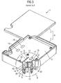
- FIG. 3 shows in a perspective view of the housing 4 with lifted off the base part 2 lid part 3 in a partially sectioned view along the line AA in FIG. 2 ,
- the base part 2, the bottom plate 20 rests directly on the wall 6 of the gear housing is made of a polyamide, which is added to a glass fiber content, manufactured by injection molding.
- the plastic used is temperature-stable up to 140 degrees Celsius and is particularly oil and vibration resistant.
- the housing 4 includes the transmitter 22 and a control circuit, which is indicated by electronic components 19 on a circuit board 5.
- a tongue-shaped spring element 11 is formed on the circuit board 5, opposite a supply of the pressure channel.
- the spring element 11 is characterized by approximately parallel to each other, edge-shaped incisions 15 formed in the support plate 5.
- the spring element 11 acts as a measuring body and forms part of the transmitter 22, whose operation will be described in more detail below.
- the housing-side opening 14 of the pressure channel 16 is closed by a membrane 13.
- the membrane 13 has on the side facing away from the pressurization side of a push rod-shaped connecting member 10 through which the diaphragm 13 is coupled to the spring element 11 of the circuit substrate 5.
- the area of the printed circuit board 5 in which the transmitter 22 is formed is supported by support screws 12 on the base part 2 of the housing 4.
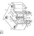
- the mode of operation of the hydraulic pressure measurement can best be determined by the FIG. 4 explain in which the detail B of the FIG. 3 is shown greatly enlarged.
- the pin-shaped part 10 establishes a force-conducting connection to the resilient element 11 of the carrier plate. Due to the rigid coupling between the diaphragm 13 and the spring element 11, depending on the size of the hydraulic pressure, a corresponding deflection of the spring element 11 occurs. An increase in the hydraulic pressure causes a deflection of the cantilever beam 11. The deflection is practically less than one millimeter , The deflection is in FIG. 4 indicated by an arrow with the reference numeral 18. On the spring element 11, a strain gauge 17 is fixed by an adhesive.
- the bending stress or shear stress of the bar-shaped part 11 is detected metrologically by these strain gauges 17, for example by detuning a diagonal voltage of a bridge circuit.
- This measuring voltage is in not shown conductors of the control circuit 19 on the Carrier plate 5 fed and evaluated directly, for example by a microcontroller.
- the microcomputer converts the deflection into a pressure value.
- strain gauge 17 In the manufacture of the strain gauge 17 can be equipped by a SMD placement machine and then be soldered in the reflow process with the other components 19 of the control circuit on the circuit board. Compared with the prior art presented at the outset, there is a considerable cost advantage in the production.
- the structure and the connection technology is due to the integration of the transmitter 22 with the support plate 5 and the control circuit creates a space-saving design.
- the short transmission path between the transmitter 22 and the electronic components 19 of the control circuit is low in terms of susceptibility and reliability.
- this can be arranged both on the thrust and / or pressure side of the spring element 11.
- the membrane 13 is made in the illustrated embodiment of plastic and made of the same material with the base part 2 of the housing 4 in injection molding.
- the membrane 13 is located in the pressure channel 16 approximately at the height of the bottom plate 20 of the base housing part. 2
- the membrane 13 may also be produced by injection molding, wherein a softer plastic is used as the material for the membrane 13 than the plastic is the base part 2.
- the base part of a metal for example of die-cast aluminum
- the membrane 13 is formed as a built-in part, which is pressed into the pressure channel 16.
- the membrane is made of metal and the actuating pin 10th is welded on the side remote from the pressure side 21 side.
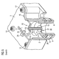
- a permanent magnet 23 is attached to the spring body 11.
- a magnetosensor 24 is arranged, which again detects the elastic deflection of the spring element 11 caused by the hydraulic pressure as a change of the permanent magnetic field. Again, from the electrical output signal of the magnetic sensor 24 of the microcontroller make a conversion to a pressure value.
- a stop may be provided in both embodiments, a stop. It is also conceivable that a support plate is provided to increase the flexural rigidity on the spring element 11.
Landscapes
- Engineering & Computer Science (AREA)
- General Engineering & Computer Science (AREA)
- Mechanical Engineering (AREA)
- Microelectronics & Electronic Packaging (AREA)
- Control Of Transmission Device (AREA)
- Measuring Fluid Pressure (AREA)
- Hydraulic Clutches, Magnetic Clutches, Fluid Clutches, And Fluid Joints (AREA)
Description
- Die Erfindung betrifft ein Steuergerät für ein Kraftfahrzeug, insbesondere zur Steuerung eines Getriebes, mit einer auf einer Trägerplatte in einem Gehäuse angeordneten elektronischen Steuerschaltung, wobei zur Messung des Hydraulikdrucks ein Messumformer vorhanden ist, der durch einen Druckkanal mit einer Hydraulikeinheit des Getriebes verbunden ist.
- In Serienfahrzeugen werden heute hoch entwickelte elektronische Steuergeräte zur Kontrolle vielfältiger Funktionen, beispielsweise zur Steuerung des Getriebes eingesetzt. Zur Steuerung eines automatischen Schaltgetriebes oder eines stufenlosen Getriebes verarbeitet die Getriebesteuerung Signale von mehreren Sensoren, u.a. auch Drucksensoren, die den Hydraulikdruck im Getriebe erfassen. Üblicherweise ist hierfür im Getriebegehäuse eine Öffnung vorgesehen, in welcher ein Druckkanal mit einem Messkolben ausgebildet ist. Der Messkolben wirkt auf einen Messumformer der die physikalische Größe Druck in ein elektrisches Signal umformt. Dieses Signal wird über Stecker und Verbindungsleitungen der Getriebesteuerungsplatine zugeführt.
- Von Nachteil ist hierbei, dass die elektrische Verbindung zwischen Messumformer und Getriebesteuerung nicht nur technisch aufwendig, sondern auch störanfällig ist. Aus der
WO 02/06651 A2 - Der vorliegenden Erfindung liegt das Problem zugrunde, ein Steuergerät zu schaffen, bei dem die Verbindung zwischen Messumformer und Steuerschaltung möglichst einfach und zuverlässig ausgeführt ist.
- Die Lösung dieses Problems erfolgt durch ein Steuergerät mit den Merkmalen des Patentanspruchs 1. Auf vorteilhafte Ausgestaltungen der Erfindung nehmen die Unteransprüche Bezug.
- Gemäß der Erfindung ist vorgesehen, in einem Bereich der Trägerplatte ein Federelement auszubilden, das Teil eines Messumformers ist, wobei das Federelement durch ein Verbindungsglied kraftleitend mit einer Membran verbunden ist, welche eine zum Federelement geführte Öffnung des Druckkanals dichtend umspannt.
- Durch diese Konstruktion wird ein mechatronisches Modul geschaffen, bei dem die bislang erforderlichen störanfälligen elektrischen Verbindungsleitungen zwischen der Getriebesteuerung und dem örtlich entfernt liegenden Messumformer entfallen.
- Für die Umformung der Durchbiegung des Federelementes in ein elektrisches Signal stehen verschiedene an sich bekannte Messprinzipien zur Auswahl, beispielsweise eine Widerstandsänderung einer Leiterstruktur.
- Das erfindungsgemäße Federelement wird hergestellt , indem der Schaltungsträger, zB. eine Leiterplatte, randseitig eingeschnitten wird. Dadurch entsteht ein zungenförmiger Tragkörper auf dem ein Dehnungsmessstreifen durch Kleben angebracht werden kann. Für die Hydraulikdruckmessung kommen dadurch die bei Dehnungsmessstreifen bekannten Auswerteschaltungen zum Einsatz.
- In einer bevorzugten Variante ist vorgesehen, dass am Federelement ein Permanentmagnet angebracht ist. Die Auslenkung des Federelementes kann durch einen auf der Trägerplatte befestigten magnetfeldabhängigen Sensor erfasst werden. Das elektrische Ausgangssignal des Messumformers ist wieder über eine Leiterstruktur auf der Trägerplatte der Steuerelektronik zugeführt.
- Bevorzugt wird das Steuergerät als mechatronisches Anbaumodul eingesetzt, dessen Gehäuse außenseitig an einer Wand des Getriebegehäuses angebaut ist. Hierbei ist am Basisteil des Gehäuses ein hohlzylindrischer Vorsprung ausgebildet, der durch eine Öffnung des Getriebegehäuses hindurch geführt ist.
- Die Fertigung ist besonders einfach, wenn die Membran, das Verbindungsglied und das Basisteil einstückig als Spritzgussteil hergestellt wird.
- Ein kompakter Aufbau wird dadurch erreicht, indem die Membran im hohlzylindrischen Vorsprung etwa im Bereich der Bodenplatte d.h. nahe zur Trägerplatte angeordnet ist.
- Bevorzugt werden bei der Herstellung polymere Werkstoffe. Hierbei hat es sich als vorteilhaft erwiesen, wenn die Membran im hohlzylindrischen Vorsprung angespritzt ist. Darüber hinaus kann es vorteilhaft sein, wenn die Membran aus einem polymere Werkstoff besteht, der eine Shore-Härte aufweist, die kleiner ist als eine Shore-Härte des Werkstoffs des Basisteils.
- Die Abdichtung des Basisteils in der Gehäusedurchführung kann auf einfache Weise durch O-Ringe erfolgen, die in Ringnuten der äußeren Mantelfläche des hohlzylindrischen Vorsprungs ausgebildet sind.
- Für die Krafteinleitung auf das Federelement ist es günstig, wenn das von der Hydraulikeinheit abgewandte Ende des Druckkanals im Wesentlichen senkrecht zur Ebene der Trägerplatte geführt ist.
- Das Trägerteil ist im Bereich der Zuführung des Druckkanals durch Stützschrauben am Basisteil abgestützt. Dadurch wird verhindert, dass die Trägerplatte im Bereich der Druckeinleitung sich auswölbt und den Messwert verfälscht.
- Die Erfindung wird nachfolgend an Hand eines in den Zeichnungen dargestellten Ausführungsbeispiels näher erläutert. Es zeigen:
- Figur 1
- das erfindungsgemäße Steuergerät, das an einer Wand eines Getriebegehäuses montiert ist in einer Seitenansicht;
- Figur 2
- das erfindungsgemäße Steuergerät gemäß
Figur 1 in einer Draufsicht; - Figur 3
- das erfindungsgemäße Steuergerät in einer perspektivischen Ansicht bei der das Deckelteil abgehoben ist;
- Figur 4
- eine erste Variante des Messumformers in einer vergrößerten Darstellung des Details B der
Figur 3 ; - Figur 5
- eine zweiten Variante des Messumformers in einer vergrößerten Darstellung des Details B der
Figur 3 . - Die
Figur 1 zeigt das Steuergerät 1 in einer bevorzugten Montagestellung außenseitig am Getriebegehäuse. Das Gehäuse 4 ist mittels Befestigungsschrauben 7 (Fig. 2 ) an der Wand 6 eines Verteilergetriebes angeschraubt. Die elektronische Steuerschaltung ist durch das Gehäuse 4 gegen Umwelteinflüsse geschützt. An einer dem Getriebe zugewandten Seite ist dein hohlzylindrischer Vorsprung 8 ausgebildet. Der hohlzylindrischen Vorsprung 8 ist durch Dichtungen 9 in der Gehäusewand 6 abgedichtet und bildet einen Teil eines Druckkanals 16, der einen Messumformer 22 (Fig. 2 ) mit einer nicht näher dargestellten Hydraulikeinheit des Getriebes verbindet. In der Zeichnung sind die aus dem Gehäuse herausgeführten Stecker und Anschlussleitungen, sowie an sich bekannte Druckausgleichselemente, die den Innenraum des Gehäuses mit dem Außenraum verbinden, der Übersichtlichkeit wegen nicht dargestellt. - Die
Figur 3 zeigt in einer perspektivischen Ansicht das Gehäuses 4 mit vom Basisteil 2 abgehobenem Deckelteil 3 in einer teilweise geschnittenen Darstellung gemäß der Linie A-A inFigur 2 . - Das Basisteil 2, dessen Bodenplatte 20 direkt an der Wand 6 des Getriebegehäuses anliegt, ist aus einem Polyamid, dem ein Glasfaseranteil beigemengt ist, in Spritzgusstechnik gefertigt. Der verwendete Kunststoff ist bis 140 Grad Celsius temperaturstabil und besonders öl- und vibrationsbeständig.
- Wie aus der geöffneten Darstellung der
Figur 3 leicht zu sehen ist, beinhaltet das Gehäuse 4 den Messumformer 22 und eine Steuerschaltung, die durch elektronische Bauteile 19 auf einer Leiterplatte 5 angedeutet ist. Auf der Leiterplatte 5 ist, gegenüberliegend einer Zuführung des Druckkanals, ein zungenförmiges Federelement 11 ausgebildet. Das Federelement 11 wird durch etwa parallel zueinander verlaufende, randseitige Einschnitte 15 in der Trägerplatte 5 gebildet. Das Federelement 11 wirkt als Messkörper und bildet einen Teil des Messumformers 22, dessen Funktionsweise weiter unten näher beschrieben wird. - Die gehäuseseitige Öffnung 14 des Druckkanals 16 ist durch eine Membran 13 abgeschlossen. Die Membran 13 besitzt an der von der Druckbeaufschlagung abgewandten Seite ein schubstangenförmiges Verbindungsglied 10, durch welches die Membran 13 an das Federelement 11 des Schaltungsträgers 5 gekoppelt ist. Der Bereich der Leiterplatte 5, in dem der Messumformers 22 ausgebildet ist, ist durch Stützschrauben 12 am Basisteil 2 des Gehäuses 4 abgestützt.
- Die Funktionsweise der Hydraulikdruckmessung lässt sich am besten an Hand der
Figur 4 erläutern, in der das Detail B derFigur 3 stark vergrößert dargestellt ist. - Sobald die Hydraulikeinheit des Getriebes im Hydrauliksystem des Fahrzeugs einen Druck aufbaut, gelangt dieser über den Druckkanal 16 an die Membran 13. Das stiftförmige Teil 10 stellt eine kraftleitende Verbindung zum federnden Element 11 der Trägerplatte her. Aufgrund der biegesteifen Kopplung zwischen der Membran 13 und dem Federelement 11 kommt es, je nach Größe des Hydraulikdrucks, zu einer entsprechenden Durchbiegung des Federelementes 11. Eine Erhöhung des Hydraulikdrucks verursacht eine Durchbiegung des einseitig eingespannten Balkens 11. Die Auslenkung liegt praktisch etwa unter einem Millimeter. Die Durchbiegung ist in
Figur 4 durch einen Pfeil mit dem Bezugszeichen 18 angedeutet. Auf dem Federelement 11 ist ein Dehnungsmessstreifen 17 durch einen Klebstoff befestigt. Die Biegespannung bzw. Schubspannung des balkenförmigen Teils 11 wird durch diesen Dehnungsmessstreifen 17 messtechnisch erfasst, beispielsweise durch Verstimmung einer Diagonalspannung einer Brückenschaltung. Diese Messspannung wird in nicht näher dargestellten Leitern der Steuerschaltung 19 auf der Trägerplatte 5 zugeführt und direkt, beispielsweise durch einen Mikrocontroller ausgewertet. Der Mikrorechner rechnet die Durchbiegung in einen Druckwert um. - Bei der Herstellung kann der Dehnungsmessstreifen 17 durch einen SMD-Bestückungsautomat bestückt werden und anschließend im Reflowverfahren mit den anderen Bauteilen 19 der Steuerschaltung auf der Leiterplatte mitgelötet werden. Verglichen mit dem eingangs dargestellten Stand der Technik ergibt sich bei der Herstellung ein erheblicher Kostenvorteil.
- Der Aufbau und die Verbindungstechnik ist durch die Integration des Messumformers 22 mit der Trägerplatt 5 bzw. der Steuerschaltung entsteht ein platzsparender Aufbau. Der kurze Übertragungsweg zwischen dem Messumformer 22 und den elektronischen Bauteilen 19 der Steuerschaltung ist hinsichtlich der Störanfälligkeit und der Zuverlässigkeit günstig. Je nach Ausführung des Dehnungsmessstreifen 17 kann dieser sowohl auf der Schub- und/oder Druckseite des Federelementes 11 angeordnet sein.
- Die Membran 13 ist im dargestellten Ausführungsbeispiel aus Kunststoff gefertigt und materialeinheitlich mit dem Basisteil 2 des Gehäuses 4 in Spritzgusstechnik hergestellt. Die Membran 13 befindet sich im Druckkanal 16 etwa in der Höhe der Bodenplatte 20 des Basisgehäuseteils 2.
Alternativ zur materialeinheitlichen Ausführung kann die Membran 13 auch durch Anspritzen hergestellt sein, wobei als Werkstoff für die Membran 13 ein weicherer Kunststoff verwendet wird, als der Kunststoff das Basisteil 2. - Selbstverständlich ist es auch möglich, dass das Basisteil aus einem Metall, beispielsweise aus Alu-Druckguss, besteht und die Membran 13 als Einbauteil ausgebildet ist, das in den Druckkanal 16 eingepresst wird. Es ist auch denkbar, dass die Membran aus Metall gefertigt wird und der Betätigungsstift 10 auf der von der Druckseite 21 abgewandte Seite angeschweißt ist.
- In einer Variante des Druckaufnehmers 22 ist am Federkörper 11 ein Permanentmagnet 23 befestigt. Auf der gegenüberliegenden Seite des Einschnitts 15 ist ein Magnetsenosor 24 angeordnet, der wieder die durch den Hydraulikdruck verursachte elastische Auslenkung des Federelements 11 als Veränderung des Permanentmagnetfeldes erfasst. Auch hier kann aus dem elektrischen Ausgangssignal des Magnetsensors 24 der Mikrokontroller eine Umrechnung in einen Druckwert vornehmen.
- Zur Begrenzung der Auslenkung des Federelementes kann in beiden Ausführungsformen ein Anschlag vorgesehen sein. Ebenso ist es denkbar, dass zur Erhöhung der Biegesteifigkeit am Federelement 11 ein Stützblech vorgesehen wird.
-
- 1
- Steuergerät
- 2
- Basisteil
- 3
- Deckelteil
- 4
- Gehäuse
- 5
- Trägerplatte, Schaltungsträger
- 6
- Getriebegehäuses
- 7
- Bohrung
- 8
- hohlzylindrischer Vorsprung
- 9
- O-Ring
- 10
- Verbindungsglied, Zwischenstück
- 11
- Federelement, planarer Federkörper
- 12
- Stützschrauben
- 13
- Membran
- 14
- Öffnung
- 15
- Einschnitt
- 16
- Druckkanal
- 17
- Dehnungsmessstreifen
- 18
- Pfeil, Auslenkung
- 19
- elektrische Bauteile
- 20
- Bodenplatte
- 21
- druckbeaufschlagte Oberfläche der Membran
- 22
- Messumformer
- 23
- Permanentmagnet
- 24
- Magnetfeldsensor
Claims (10)
- Steuergerät für ein Kraftfahrzeug, insbesondere zur Steuerung eines Getriebes, mit einer auf einer Trägerplatte (5) in einem Gehäuse (4) angeordneten elektronischen Steuerschaltung, wobei zur Messung des Hydraulikdrucks ein Messumformer (22) durch einen Druckkanal (16) mit einer Hydraulikeinheit des Getriebes verbunden ist, und wobei in einem Bereich der Trägerplatte (5) ein Federelement (11) ausgebildet ist, das Teil des Messumformers (22) ist, dadurch gekennzeichnet, dass das Federelement (11) durch ein Verbindungsglied (10) kraftleitend mit einer Membran (13) verbunden ist, welche eine zum Federelement (11) geführte Öffnung (14) des Druckkanals (16) dichtend umspannt, dass an der Trägerplatte (5) randseitige Einschnitte (15) vorhanden sind und das Federelement (11) zungenförmig ausgebildet ist.
- Vorrichtung nach Anspruch 1 oder 2, dadurch gekennzeichnet, dass am Federelement (11) ein Dehnungsmessstreifen (17) angebracht ist, durch den die Auslenkung (18) des Federelementes (11) messtechnisch erfassbar ist.
- Steuergerät nach Anspruch 1 oder 2, dadurch gekennzeichnet, dass am Federelement (11) ein Permanentmagnet (23) angebracht ist durch und eine Auslenkung (18) des Federelementes (11) durch einen magnetfeldabhängigen Sensor auf der Trägerplatte (5) messtechnisch erfassbar ist.
- Steuergerät nach einem der Ansprüche 1 bis 4, dadurch gekennzeichnet, dass das Gehäuse (4) außenseitig an einer Wand des Getriebegehäuses (6) angeordnet ist, dass der Druckkanal (16) in einem eine Öffnung des Getriebegehäuses hindurchragenden Abschnitt durch ein am Basisteil (2) des Gehäuses (4) ausgebildeten hohlzylindrischen Vorsprung (8) gebildet ist.
- Steuergerät nach einem der vorstehenden Ansprüche, dadurch gekennzeichnet, dass die Membran (13), das Verbindungsglied (10) und das Basisteil (2) einstückig als Spritzgussteil hergestellt sind.
- Steuergerät nach einem der vorstehenden Ansprüche, dadurch gekennzeichnet, dass die Membran (13) im hohlzylindrischen Vorsprung (8) etwa im Bereich der Bodenplatte (20) angeordnet ist.
- Steuergerät nach Anspruch 6 oder 7, dadurch gekennzeichnet, dass die Membran (13) im hohlzylindrischen Vorsprung (8) angespritzt ist und aus einem polymeren Werkstoff besteht, der eine Shore-Härte aufweist, die kleiner ist als die Shore-Härte des Werkstoffs des Basisteils (2).
- Steuergerät nach einem der Ansprüche 5 bis 8, dadurch gekennzeichnet, dass an der äußeren Mantelfläche des hohlzylindrischen Vorsprungs (8) Ringnuten zur Aufnahme von ringförmigen Dichtelementen (9) vorgesehen sind.
- Steuergerät nach einem der vorstehenden Ansprüche, dadurch gekennzeichnet, dass das von der Hydraulikeinheit abgewandte Ende des Druckkanals (16) im wesentlichen senkrecht zur Ebene der Trägerplatte (5) geführt ist.
- Steuergerät nach einem der vorstehenden Ansprüche,
dadurch gekennzeichnet, dass das Trägerteil (5) im Bereich der Zuführung des Druckkanals (16) durch Stützschrauben (12) am Basisteil (2) abstützt ist.
Applications Claiming Priority (2)
| Application Number | Priority Date | Filing Date | Title |
|---|---|---|---|
| AT18822003 | 2003-11-24 | ||
| AT0188203A AT412815B (de) | 2003-11-24 | 2003-11-24 | Steuergerät für ein getriebe in einem kraftfahrzeug |
Publications (3)
| Publication Number | Publication Date |
|---|---|
| EP1533189A2 EP1533189A2 (de) | 2005-05-25 |
| EP1533189A3 EP1533189A3 (de) | 2007-02-28 |
| EP1533189B1 true EP1533189B1 (de) | 2010-01-20 |
Family
ID=33494533
Family Applications (1)
| Application Number | Title | Priority Date | Filing Date |
|---|---|---|---|
| EP04024381A Expired - Lifetime EP1533189B1 (de) | 2003-11-24 | 2004-10-13 | Steuergerät für ein Kraftfahrzeug |
Country Status (4)
| Country | Link |
|---|---|
| US (1) | US7174778B2 (de) |
| EP (1) | EP1533189B1 (de) |
| AT (2) | AT412815B (de) |
| DE (1) | DE502004010670D1 (de) |
Families Citing this family (5)
| Publication number | Priority date | Publication date | Assignee | Title |
|---|---|---|---|---|
| DE102006029977B3 (de) * | 2006-06-29 | 2008-01-17 | Siemens Ag | Steuervorrichtung |
| USD738327S1 (en) * | 2014-02-09 | 2015-09-08 | Prettl Electric Corporation | Switch housing platform |
| USD738326S1 (en) * | 2014-02-09 | 2015-09-08 | Prettl Electric Corporation | Switch housing platform |
| DE102017223177A1 (de) | 2017-12-19 | 2019-06-19 | Conti Temic Microelectronic Gmbh | Druckmesseinheit und Anschlussbaueinheit für ein Kraftfahrzeug-Getriebe. |
| DE102018217657A1 (de) * | 2018-10-15 | 2020-07-09 | Conti Temic Microelectronic Gmbh | Drucksensor und Fertigungsverfahren, Getriebesteuergerät und Getriebe |
Family Cites Families (18)
| Publication number | Priority date | Publication date | Assignee | Title |
|---|---|---|---|---|
| DE3232817C1 (de) * | 1982-09-03 | 1988-09-08 | Endress U. Hauser Gmbh U. Co, 7867 Maulburg | Biegefeder |
| US4758695A (en) * | 1986-09-03 | 1988-07-19 | Texas Instruments Incorporated | Automotive transmission control system and improved longevity therefor |
| JPH0545941Y2 (de) * | 1986-09-30 | 1993-11-30 | ||
| US4993506A (en) * | 1989-12-11 | 1991-02-19 | Shlomo Angel | Mass-produced flat one-piece load cell and scales incorporating it |
| KR930011091B1 (ko) * | 1990-06-08 | 1993-11-20 | 미쯔비시 덴끼 가부시끼가이샤 | 압력 센서 |
| DE4447513C2 (de) * | 1994-07-28 | 2001-12-06 | Siemens Ag | Wasserdichtes Gehäuse zum Schutz von Elektronikschaltkreisen |
| DE29714223U1 (de) * | 1997-08-08 | 1997-11-20 | Leopold Kostal GmbH & Co KG, 58507 Lüdenscheid | Getriebesteuerung für ein Kraftfahrzeug |
| DE29714229U1 (de) * | 1997-08-08 | 1997-11-20 | Leopold Kostal GmbH & Co KG, 58507 Lüdenscheid | Bodenplatte für Getriebesteuerung |
| US6192743B1 (en) * | 1998-02-25 | 2001-02-27 | Siemens Canada Limited | Self-contained leak detection module having enclosure-mounted toggle levers for pump and valve |
| DE19830538A1 (de) * | 1998-07-08 | 2000-01-20 | Siemens Ag | Drucksensor-Anordnung, insbesondere zur Druckerfassung in einem ölbeaufschlagten Druckbereich eines Kraftfahrzeuggetriebes |
| DE19834212A1 (de) * | 1998-07-29 | 2000-02-10 | Siemens Ag | Steuergerät in einem Kraftfahrzeug und von diesem verwendeter Drucksensor |
| WO2000011376A2 (de) * | 1998-08-24 | 2000-03-02 | Siemens Aktiengesellschaft | Steuergerät in einem kraftfahrzeug |
| JP2000121469A (ja) * | 1998-10-16 | 2000-04-28 | Mitsubishi Electric Corp | 圧力センサ |
| DE10034876C1 (de) * | 2000-07-18 | 2002-02-28 | Siemens Ag | Kraftfahrzeug-Steuergerät mit integriertem Druckschalter |
| DE10043448C2 (de) * | 2000-09-04 | 2002-08-01 | Siemens Ag | Steuergerät |
| WO2002066868A1 (en) * | 2001-02-15 | 2002-08-29 | Siemens Vdo Automotive Corporation | Mechatronics pressure sensor and contact |
| JP4801274B2 (ja) * | 2001-03-29 | 2011-10-26 | 本田技研工業株式会社 | 圧力センサを内蔵した制御箱 |
| US6880405B2 (en) * | 2002-12-30 | 2005-04-19 | Pti Technologies, Inc. | Electrical/visual differential pressure indicator with solid state sensor |
-
2003
- 2003-11-24 AT AT0188203A patent/AT412815B/de not_active IP Right Cessation
-
2004
- 2004-10-13 EP EP04024381A patent/EP1533189B1/de not_active Expired - Lifetime
- 2004-10-13 AT AT04024381T patent/ATE455983T1/de active
- 2004-10-13 DE DE502004010670T patent/DE502004010670D1/de not_active Expired - Lifetime
- 2004-11-24 US US10/996,042 patent/US7174778B2/en not_active Expired - Fee Related
Also Published As
| Publication number | Publication date |
|---|---|
| ATE455983T1 (de) | 2010-02-15 |
| EP1533189A2 (de) | 2005-05-25 |
| AT412815B (de) | 2005-07-25 |
| US20050109156A1 (en) | 2005-05-26 |
| US7174778B2 (en) | 2007-02-13 |
| DE502004010670D1 (de) | 2010-03-11 |
| ATA18822003A (de) | 2004-12-15 |
| EP1533189A3 (de) | 2007-02-28 |
Similar Documents
| Publication | Publication Date | Title |
|---|---|---|
| EP2167930B1 (de) | Anschlusseinheit für eine druckmesszelle | |
| EP1718937B1 (de) | Sensorhalter und verfahren zu dessen herstellung | |
| DE102014200093A1 (de) | Sensor zur Erfassung einer Temperatur und eines Drucks eines fluiden Mediums | |
| EP2520142B1 (de) | Sensor mit gehäuse und verfahren zu dessen herstellung | |
| DE112010000835T5 (de) | Drehlagesensor | |
| DE10024921A1 (de) | Pedalweggebereinheit | |
| DE202008009002U1 (de) | Magnetfeldsensor | |
| DE19811970A1 (de) | Meßanzeigevorrichtung | |
| EP1890162A2 (de) | Elektrische Mess-Vorrichtung | |
| EP2690412B1 (de) | Sensor | |
| EP1533189B1 (de) | Steuergerät für ein Kraftfahrzeug | |
| DE102008042314A1 (de) | Miniatur-Temperaturtransmitter | |
| DE102006018365B4 (de) | Druckerfassungsvorrichtung vom Membrantyp | |
| EP1586868B1 (de) | Positionssensoranordnung mit mehreren in einer Reihe angeordneten, magnetfeldsensitiven Sensoren, insbesondere Hall-Sensoren | |
| DE10341277A1 (de) | Pedal-Vorrichtung für Kraftfahrzeuge | |
| DE202007002864U1 (de) | Gabelgehäuse, insbesondere für Licht- oder Ultraschallschranken | |
| DE102009005490B3 (de) | Elektronischer Heizkostenverteiler | |
| DE102007016473A1 (de) | Anschlusseinheit für eine Druckmesszelle | |
| DE102019120683B4 (de) | Feldgerät und Deckel für ein Feldgerät | |
| DE10034876C1 (de) | Kraftfahrzeug-Steuergerät mit integriertem Druckschalter | |
| DE10303078A1 (de) | Anordnung zum Messen eines Druckes in einem flüssigen oder gasförmigen Medium | |
| DE102022105605B3 (de) | Sensoreinheit | |
| WO2008049690A1 (de) | Magnetfeldsensor | |
| DE102007016536B4 (de) | Vorrichtung zur Messung eines in einem Druckmedium herrschenden Drucks | |
| EP3084380A1 (de) | Relativdrucksensor |
Legal Events
| Date | Code | Title | Description |
|---|---|---|---|
| PUAI | Public reference made under article 153(3) epc to a published international application that has entered the european phase |
Free format text: ORIGINAL CODE: 0009012 |
|
| AK | Designated contracting states |
Kind code of ref document: A2 Designated state(s): AT BE BG CH CY CZ DE DK EE ES FI FR GB GR HU IE IT LI LU MC NL PL PT RO SE SI SK TR |
|
| AX | Request for extension of the european patent |
Extension state: AL HR LT LV MK |
|
| PUAL | Search report despatched |
Free format text: ORIGINAL CODE: 0009013 |
|
| AK | Designated contracting states |
Kind code of ref document: A3 Designated state(s): AT BE BG CH CY CZ DE DK EE ES FI FR GB GR HU IE IT LI LU MC NL PL PT RO SE SI SK TR |
|
| AX | Request for extension of the european patent |
Extension state: AL HR LT LV MK |
|
| RIC1 | Information provided on ipc code assigned before grant |
Ipc: F16H 61/00 20060101AFI20070123BHEP Ipc: G01L 9/00 20060101ALI20070123BHEP |
|
| 17P | Request for examination filed |
Effective date: 20070822 |
|
| AKX | Designation fees paid |
Designated state(s): AT BE BG CH CY CZ DE DK EE ES FI FR GB GR HU IE IT LI LU MC NL PL PT RO SE SI SK TR |
|
| 17Q | First examination report despatched |
Effective date: 20090210 |
|
| GRAP | Despatch of communication of intention to grant a patent |
Free format text: ORIGINAL CODE: EPIDOSNIGR1 |
|
| GRAS | Grant fee paid |
Free format text: ORIGINAL CODE: EPIDOSNIGR3 |
|
| GRAA | (expected) grant |
Free format text: ORIGINAL CODE: 0009210 |
|
| AK | Designated contracting states |
Kind code of ref document: B1 Designated state(s): AT BE BG CH CY CZ DE DK EE ES FI FR GB GR HU IE IT LI LU MC NL PL PT RO SE SI SK TR |
|
| REG | Reference to a national code |
Ref country code: GB Ref legal event code: FG4D Free format text: NOT ENGLISH |
|
| REG | Reference to a national code |
Ref country code: CH Ref legal event code: EP |
|
| REG | Reference to a national code |
Ref country code: CH Ref legal event code: NV Representative=s name: SIEMENS SCHWEIZ AG |
|
| REG | Reference to a national code |
Ref country code: IE Ref legal event code: FG4D |
|
| RAP2 | Party data changed (patent owner data changed or rights of a patent transferred) |
Owner name: MELECS EWS GMBH & CO KG |
|
| REF | Corresponds to: |
Ref document number: 502004010670 Country of ref document: DE Date of ref document: 20100311 Kind code of ref document: P |
|
| REG | Reference to a national code |
Ref country code: NL Ref legal event code: VDEP Effective date: 20100120 |
|
| PG25 | Lapsed in a contracting state [announced via postgrant information from national office to epo] |
Ref country code: ES Free format text: LAPSE BECAUSE OF FAILURE TO SUBMIT A TRANSLATION OF THE DESCRIPTION OR TO PAY THE FEE WITHIN THE PRESCRIBED TIME-LIMIT Effective date: 20100501 Ref country code: PT Free format text: LAPSE BECAUSE OF FAILURE TO SUBMIT A TRANSLATION OF THE DESCRIPTION OR TO PAY THE FEE WITHIN THE PRESCRIBED TIME-LIMIT Effective date: 20100520 Ref country code: NL Free format text: LAPSE BECAUSE OF FAILURE TO SUBMIT A TRANSLATION OF THE DESCRIPTION OR TO PAY THE FEE WITHIN THE PRESCRIBED TIME-LIMIT Effective date: 20100120 |
|
| REG | Reference to a national code |
Ref country code: IE Ref legal event code: FD4D |
|
| PG25 | Lapsed in a contracting state [announced via postgrant information from national office to epo] |
Ref country code: FI Free format text: LAPSE BECAUSE OF FAILURE TO SUBMIT A TRANSLATION OF THE DESCRIPTION OR TO PAY THE FEE WITHIN THE PRESCRIBED TIME-LIMIT Effective date: 20100120 Ref country code: PL Free format text: LAPSE BECAUSE OF FAILURE TO SUBMIT A TRANSLATION OF THE DESCRIPTION OR TO PAY THE FEE WITHIN THE PRESCRIBED TIME-LIMIT Effective date: 20100120 Ref country code: SI Free format text: LAPSE BECAUSE OF FAILURE TO SUBMIT A TRANSLATION OF THE DESCRIPTION OR TO PAY THE FEE WITHIN THE PRESCRIBED TIME-LIMIT Effective date: 20100120 |
|
| PG25 | Lapsed in a contracting state [announced via postgrant information from national office to epo] |
Ref country code: EE Free format text: LAPSE BECAUSE OF FAILURE TO SUBMIT A TRANSLATION OF THE DESCRIPTION OR TO PAY THE FEE WITHIN THE PRESCRIBED TIME-LIMIT Effective date: 20100120 Ref country code: RO Free format text: LAPSE BECAUSE OF FAILURE TO SUBMIT A TRANSLATION OF THE DESCRIPTION OR TO PAY THE FEE WITHIN THE PRESCRIBED TIME-LIMIT Effective date: 20100120 Ref country code: GR Free format text: LAPSE BECAUSE OF FAILURE TO SUBMIT A TRANSLATION OF THE DESCRIPTION OR TO PAY THE FEE WITHIN THE PRESCRIBED TIME-LIMIT Effective date: 20100421 Ref country code: IE Free format text: LAPSE BECAUSE OF FAILURE TO SUBMIT A TRANSLATION OF THE DESCRIPTION OR TO PAY THE FEE WITHIN THE PRESCRIBED TIME-LIMIT Effective date: 20100120 Ref country code: SE Free format text: LAPSE BECAUSE OF FAILURE TO SUBMIT A TRANSLATION OF THE DESCRIPTION OR TO PAY THE FEE WITHIN THE PRESCRIBED TIME-LIMIT Effective date: 20100120 Ref country code: CY Free format text: LAPSE BECAUSE OF FAILURE TO SUBMIT A TRANSLATION OF THE DESCRIPTION OR TO PAY THE FEE WITHIN THE PRESCRIBED TIME-LIMIT Effective date: 20100120 |
|
| PLBE | No opposition filed within time limit |
Free format text: ORIGINAL CODE: 0009261 |
|
| STAA | Information on the status of an ep patent application or granted ep patent |
Free format text: STATUS: NO OPPOSITION FILED WITHIN TIME LIMIT |
|
| PG25 | Lapsed in a contracting state [announced via postgrant information from national office to epo] |
Ref country code: BG Free format text: LAPSE BECAUSE OF FAILURE TO SUBMIT A TRANSLATION OF THE DESCRIPTION OR TO PAY THE FEE WITHIN THE PRESCRIBED TIME-LIMIT Effective date: 20100420 Ref country code: SK Free format text: LAPSE BECAUSE OF FAILURE TO SUBMIT A TRANSLATION OF THE DESCRIPTION OR TO PAY THE FEE WITHIN THE PRESCRIBED TIME-LIMIT Effective date: 20100120 Ref country code: CZ Free format text: LAPSE BECAUSE OF FAILURE TO SUBMIT A TRANSLATION OF THE DESCRIPTION OR TO PAY THE FEE WITHIN THE PRESCRIBED TIME-LIMIT Effective date: 20100120 |
|
| 26N | No opposition filed |
Effective date: 20101021 |
|
| PG25 | Lapsed in a contracting state [announced via postgrant information from national office to epo] |
Ref country code: DK Free format text: LAPSE BECAUSE OF FAILURE TO SUBMIT A TRANSLATION OF THE DESCRIPTION OR TO PAY THE FEE WITHIN THE PRESCRIBED TIME-LIMIT Effective date: 20100120 |
|
| PG25 | Lapsed in a contracting state [announced via postgrant information from national office to epo] |
Ref country code: MC Free format text: LAPSE BECAUSE OF NON-PAYMENT OF DUE FEES Effective date: 20101031 |
|
| PGFP | Annual fee paid to national office [announced via postgrant information from national office to epo] |
Ref country code: CH Payment date: 20120110 Year of fee payment: 8 |
|
| PGFP | Annual fee paid to national office [announced via postgrant information from national office to epo] |
Ref country code: DE Payment date: 20111219 Year of fee payment: 8 |
|
| PG25 | Lapsed in a contracting state [announced via postgrant information from national office to epo] |
Ref country code: LU Free format text: LAPSE BECAUSE OF NON-PAYMENT OF DUE FEES Effective date: 20101013 Ref country code: HU Free format text: LAPSE BECAUSE OF FAILURE TO SUBMIT A TRANSLATION OF THE DESCRIPTION OR TO PAY THE FEE WITHIN THE PRESCRIBED TIME-LIMIT Effective date: 20100721 |
|
| PG25 | Lapsed in a contracting state [announced via postgrant information from national office to epo] |
Ref country code: TR Free format text: LAPSE BECAUSE OF FAILURE TO SUBMIT A TRANSLATION OF THE DESCRIPTION OR TO PAY THE FEE WITHIN THE PRESCRIBED TIME-LIMIT Effective date: 20100120 |
|
| PGFP | Annual fee paid to national office [announced via postgrant information from national office to epo] |
Ref country code: FR Payment date: 20121031 Year of fee payment: 9 |
|
| PGFP | Annual fee paid to national office [announced via postgrant information from national office to epo] |
Ref country code: GB Payment date: 20121011 Year of fee payment: 9 Ref country code: BE Payment date: 20121112 Year of fee payment: 9 Ref country code: IT Payment date: 20121030 Year of fee payment: 9 |
|
| PGFP | Annual fee paid to national office [announced via postgrant information from national office to epo] |
Ref country code: AT Payment date: 20120912 Year of fee payment: 9 |
|
| REG | Reference to a national code |
Ref country code: CH Ref legal event code: PL |
|
| PG25 | Lapsed in a contracting state [announced via postgrant information from national office to epo] |
Ref country code: CH Free format text: LAPSE BECAUSE OF NON-PAYMENT OF DUE FEES Effective date: 20121031 Ref country code: LI Free format text: LAPSE BECAUSE OF NON-PAYMENT OF DUE FEES Effective date: 20121031 Ref country code: DE Free format text: LAPSE BECAUSE OF NON-PAYMENT OF DUE FEES Effective date: 20130501 |
|
| REG | Reference to a national code |
Ref country code: DE Ref legal event code: R119 Ref document number: 502004010670 Country of ref document: DE Effective date: 20130501 |
|
| BERE | Be: lapsed |
Owner name: MELECS EWS GMBH & CO. KG Effective date: 20131031 |
|
| REG | Reference to a national code |
Ref country code: AT Ref legal event code: MM01 Ref document number: 455983 Country of ref document: AT Kind code of ref document: T Effective date: 20131013 |
|
| GBPC | Gb: european patent ceased through non-payment of renewal fee |
Effective date: 20131013 |
|
| PG25 | Lapsed in a contracting state [announced via postgrant information from national office to epo] |
Ref country code: GB Free format text: LAPSE BECAUSE OF NON-PAYMENT OF DUE FEES Effective date: 20131013 |
|
| REG | Reference to a national code |
Ref country code: FR Ref legal event code: ST Effective date: 20140630 |
|
| PG25 | Lapsed in a contracting state [announced via postgrant information from national office to epo] |
Ref country code: FR Free format text: LAPSE BECAUSE OF NON-PAYMENT OF DUE FEES Effective date: 20131031 Ref country code: IT Free format text: LAPSE BECAUSE OF NON-PAYMENT OF DUE FEES Effective date: 20131013 Ref country code: AT Free format text: LAPSE BECAUSE OF NON-PAYMENT OF DUE FEES Effective date: 20131013 |
|
| PG25 | Lapsed in a contracting state [announced via postgrant information from national office to epo] |
Ref country code: BE Free format text: LAPSE BECAUSE OF NON-PAYMENT OF DUE FEES Effective date: 20131031 |