EP1533179B1 - Hubladebühne - Google Patents
Hubladebühne Download PDFInfo
- Publication number
- EP1533179B1 EP1533179B1 EP04025268A EP04025268A EP1533179B1 EP 1533179 B1 EP1533179 B1 EP 1533179B1 EP 04025268 A EP04025268 A EP 04025268A EP 04025268 A EP04025268 A EP 04025268A EP 1533179 B1 EP1533179 B1 EP 1533179B1
- Authority
- EP
- European Patent Office
- Prior art keywords
- supporting tube
- cover
- support tube
- loading tailgate
- loading
- Prior art date
- Legal status (The legal status is an assumption and is not a legal conclusion. Google has not performed a legal analysis and makes no representation as to the accuracy of the status listed.)
- Expired - Lifetime
Links
- 238000007789 sealing Methods 0.000 claims description 34
- 229920003023 plastic Polymers 0.000 claims description 7
- 230000006978 adaptation Effects 0.000 claims 1
- 210000004907 gland Anatomy 0.000 description 4
- 230000001276 controlling effect Effects 0.000 description 3
- 239000000463 material Substances 0.000 description 3
- 229920002457 flexible plastic Polymers 0.000 description 2
- 230000001105 regulatory effect Effects 0.000 description 2
- 239000000853 adhesive Substances 0.000 description 1
- 238000004026 adhesive bonding Methods 0.000 description 1
- 230000001070 adhesive effect Effects 0.000 description 1
- 150000001875 compounds Chemical class 0.000 description 1
- 230000001419 dependent effect Effects 0.000 description 1
- 230000007613 environmental effect Effects 0.000 description 1
- 239000003566 sealing material Substances 0.000 description 1
- 238000003466 welding Methods 0.000 description 1
- -1 wherein a flexible Substances 0.000 description 1
Images




Classifications
-
- B—PERFORMING OPERATIONS; TRANSPORTING
- B60—VEHICLES IN GENERAL
- B60P—VEHICLES ADAPTED FOR LOAD TRANSPORTATION OR TO TRANSPORT, TO CARRY, OR TO COMPRISE SPECIAL LOADS OR OBJECTS
- B60P1/00—Vehicles predominantly for transporting loads and modified to facilitate loading, consolidating the load, or unloading
- B60P1/44—Vehicles predominantly for transporting loads and modified to facilitate loading, consolidating the load, or unloading having a loading platform thereon raising the load to the level of the load-transporting element
- B60P1/4471—General means for controlling movements of the loading platform, e.g. hydraulic systems
-
- H—ELECTRICITY
- H02—GENERATION; CONVERSION OR DISTRIBUTION OF ELECTRIC POWER
- H02G—INSTALLATION OF ELECTRIC CABLES OR LINES, OR OF COMBINED OPTICAL AND ELECTRIC CABLES OR LINES
- H02G11/00—Arrangements of electric cables or lines between relatively-movable parts
Definitions
- the invention relates to a tail lift for arrangement on a rear side of a vehicle according to the preamble of claim 1. Furthermore, the invention relates to a tail lift according to the preamble of claim 10.
- the support tube is usually arranged transversely to the direction of travel of the vehicle and serves to support a loading platform, which is usually mounted pivotably and liftable or lowered on the support tube.
- a loading platform which is usually mounted pivotably and liftable or lowered on the support tube.
- motors or pressure medium cylinders of the same are connected via electrical lines to a control unit.
- the electrical cables or cables are routed in practice from the loading platform along the support tube. From the support tube, the lines then extend to an operating unit or a control unit. The laying of cables or cables is associated with a considerable structural complexity.
- the present invention seeks to further develop tail lifts of the type mentioned, but at least to add a further embodiment of the prior art.
- a sealing cap for closing open ends of the support tube consists of at least two articulated, in particular hinge-like, interconnected parts.
- a first part in particular a holding part, can be fastened to the support tube and has a passage for at least one cable.
- a second part, in particular a cover is connected in an articulated manner to the first part in such a way that it is designed to close the open end of the support tube which is released from the first part.
- Such a trained sealing cap has many advantages. The attachment of the first part, in particular of the holding part, on the support tube, a loss or loss of the opening occlusive second part, in particular the lid to exclude.
- the second part namely the holding part
- at least partially the support tube can be positioned on the same enclosing.
- the holding part is preferably arranged in the region or in the vicinity of the open end of the support tube. This can be done solvable.
- more permanent fixings of the holding part on the support tube are conceivable, for example by gluing or riveting, welding or the like.
- the holding part may have recesses.
- the recesses may be arranged on a side surface of the holding part associated with the support tube. It is also conceivable that the cables are passed through openings in the holding part.
- the recesses or openings extend in the longitudinal direction of the cables, wherein each cable or each line can be assigned its own or separate recess.
- the recesses may in this case be distributed over the cross section, so that the cables are at least laid clean in this area and easily accessible.
- the Holding part to be formed of plastic. It is also conceivable that the holding part in the region of the recesses consists of a plastic with increased flexibility, whereas other parts or of the holding part, moreover, consists of a stiffer plastic.
- the second part of the sealing cap namely a cover, preferably has a shape corresponding to the cross-sectional shape of the support tube.
- the lid for closing the open end of the support tube is pivotally attached to the holding part.
- the lid can be easily moved between a closed position and an open position, without the lid must be completely removed from the support tube.
- the lid In the closed position, the lid should preferably completely cover or close the open end of the support tube. Conceivable for this purpose is a positive arrangement of the lid in the region of the open end of the support tube.
- the lid essentially only closes the open end and, for example, areas for carrying the cables or lines remain free in the interior of the support tube.
- the cover sealingly closes the open end of the support tube and is formed for this purpose of a flexible material, such as a soft plastic.
- the lid may, like the holding part, also consist of a plurality of different materials, wherein a flexible, sealing material is provided only in the region which comes to bear on the support tube.
- the lid is arranged in the closed position such that the outer end of the support tube is enclosed on the outside.
- the cover may have a circumferential collar, which preferably rests positively on the outside of the support tube in the region of an open end.
- the lid is inserted into the open end of the support tube, such as in the form of a plug.
- control unit is arranged in the support tube.
- the control unit may contain electronic and / or electrical components for the control and / or regulation and / or display and / or control of functions of the tail lifts.
- the arrangement of these means in the support tube these are protected from environmental influences and continue to be easily accessible.
- Another advantage of this solution is that it reduces the length of lines needed to cabling the tail lift.
- the control unit is preferably arranged in the region of free ends of the support tube.
- the control unit may be associated with a sealing cap for closing open ends of the support tube.
- the sealing cap can be the sealing cap according to the invention described above.
- the control unit is arranged on the sealing cap, that when the sealing cap is arranged on the support tube, the control unit is arranged in the (interior of) the support tube.
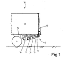
- Fig. 1 shows a vehicle, namely a truck 10.
- the truck 10 has a structure 11, which may be a so-called box body with a fully open back. The remaining walls of the structure may be formed closed.
- the back of the truck 10 is assigned a tail lift 12. Trained in the usual way tail lift 12 has a hoist 13, which on a chassis frame 14 of the truck 10th is arranged.
- the hoist 13 carries a loading platform 15, which in the in Fig. 1 shown closed position, the open back of the structure 11 completely closes.
- the hoist 13 has pivotally mounted on a transverse support tube 16 handlebar 17, which are pivotally connected to the loading platform 15.
- Pressure cylinder 18, in particular hydraulic cylinder, are used for pivoting the loading platform 15 about a horizontal axis of rotation.
- Further pressure cylinder 19, which are preferably also designed as a hydraulic cylinder, serve to raise and lower the loading platform 15.
- the loading platform 15 is thus mounted on the lifting mechanism 13 on the support tube 16, which in turn is associated with the chassis frame 14.
- the support tube 16 serving as a crossbeam has a preferably continuous cavity, so that lateral free ends 20 of the support tube 16 have openings 21. These openings 21 can each be closed by a specially designed sealing cap 22.
- the sealing cap 22 according to the invention consists of at least two parts, namely a first part for fixing the sealing cap 22 on the support tube 16 and a second part for closing the openings 21 in the region of the free ends 20 of the support tube 16.
- the first and the second part of the sealing cap 22nd are hinged together.
- the first part of the sealing cap 22 for attachment to the support tube 16 is referred to as a holding part 23.
- the second part of the sealing cap 22 for closing the openings 21 is referred to as cover 24.
- the lid 24 is pivotally connected in a lateral edge region with the holding part 23.
- a residual connection in particular a film hinge, is used for this purpose, which is designed in the manner of a line joint 25.
- the lid 24 is arranged in this way about the line joint 25 pivotally mounted on the holding part 23.
- the lid 24 can be pivoted about the hinge.
- the hinge-like connection can also be designed in other ways.
- the sealing cap 22 is formed from plastic, preferably a residual compound is used.
- the holding part 23 is fixed to a side surface 26 or side wall of the support tube 16.
- two fastening means 27 are used in the present case.
- the fastening means 27 may be releasable fastening means 27 such as screws or the like.
- rivet connections can also be used for fastening the holding part 23.
- adhesive bonds or the like come into question.
- the holding part 23 is arranged with the fastening means 27 directly at the free end 20 of the support tube 16, so that the holding part 23 and the free end 20 of the support tube 16 are arranged on the outside in alignment.
- the holding part 23 is approximately U-shaped in the embodiment shown, with a web 28 which extends completely over the side surface 26 of the support tube 16 and preferably rests against the outside of the support tube 16.
- two short flanges 29 are arranged or formed, respectively, which surround the support tube 16 at two opposite side surfaces 30.
- the holding part 23, the support tube 16 also enclose to a greater extent or completely.
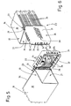
- the pivotally mounted on the holding part 23 cover 24 consists of a top wall 31 and the edge thereof arranged collar walls 32, which together form a preferably circumferential collar.
- the cover 24 is adapted to the cross-sectional shape of the support tube 16 such that it closes the openings 21 in the region of the free ends 20 in a closed position.
- the collar walls 32 are for this purpose angled relative to the top wall 31, in the present embodiment by an angle of 90 °. In the closed position of the lid 24, the collar walls 32 bear against the outside on the side surfaces of the support tube 16. At least the collar walls 32 may be formed of a flexible plastic, so that a positive or sealing engagement on the outside of the support tube 16 is facilitated.
- a part of the collar is formed by the holding part 23.
- a recess 33 or notch is provided in the collar walls 32 of the lid 24, in which the holding part 23 is in the closed position of the lid 24 receiving.
- the collar or collar walls 32 are formed by the holding part 23.
- web-like projections 34 are further formed in the region of the collar walls 32, which can serve to stiffen the lid 24 and as a handle.
- a gripping tab 35 is additionally formed, which can likewise serve to grip the lid 24.
- a logo 39 of the manufacturer or an advertising imprint or the like is also applied, for example formed, in the exemplary embodiment shown.
- the lines 36 are used to connect the various control, display, control elements, hoists 23 and pressure cylinder 18, 19 with each other.
- the lines 36 lead to a control unit 37, which is arranged according to the invention in the support tube 16.
- control unit 37 may merely be a control box or distribution box, which may serve, for example, for wiring the individual components of the tail lift 12.
- control unit 37 may also include electronic and / or electrical components for controlling and / or regulating and / or displaying and / or controlling (all) functions of the tail lift 12.
- the control unit 37 is arranged on an inner side of the cover 24 or the cover wall 31, such that in a closed position of the cover 24 (FIG. Fig. 2 or 3) the control unit 37 is positioned in the support tube 16.
- the sealing cap 22 has a cable gland. This is formed in the region of the holding part 23.
- the web 28 of the holding part 23 has recesses 38 for this purpose.
- the recesses 38 are formed starting from a side surface of the web 28, as grooves or channels.
- the side surface of the web 28 is the surface facing the side surface 26 of the support tube 16.
- Fig. 7 shows, the lines 36 are laid parallel and spaced apart on the outside of the support tube 16.
- a separate recess 38 is provided in the holding part 23.
- several lines 36 can be passed through a single recess 38.
- the holding part 23 may be formed of a suitable, flexible plastic.
- a material with an increased flexibility may be present, so that not occupied by lines 36 recesses 38 can be sealed.
- special seals can be used.
- lines 36 extend through the recess 33 and notch in the collar walls 32 of the lid 24 and can be connected in this way to the control unit 37.
- the support tube 16 and the lid 24 have a matching, in the illustrated embodiment, substantially rectangular or square, cross-sectional shape.
- the sealing cap 22 according to the invention can also be adapted to other cross-sectional shapes of the support tube 16, for example to circular or oval cross-sections.
- the position of the hinge connection between the cover 24 and holding member 23 must be adjusted.
- the remainder of the connection or the like is arranged in the cover 24 and extends at a distance from the edge of the cover 24, so that it is pivotable against the support tube 16 for closing the opening 21.
Landscapes
- Engineering & Computer Science (AREA)
- Transportation (AREA)
- Mechanical Engineering (AREA)
- Seal Device For Vehicle (AREA)
- Gripping On Spindles (AREA)
- Paper (AREA)
- Vehicle Body Suspensions (AREA)
- Cooling, Air Intake And Gas Exhaust, And Fuel Tank Arrangements In Propulsion Units (AREA)
- Pressure Vessels And Lids Thereof (AREA)
- Loading And Unloading Of Fuel Tanks Or Ships (AREA)
- Closures For Containers (AREA)
- Flexible Shafts (AREA)
- Clamps And Clips (AREA)
Description
- Die Erfindung betrifft eine Hubladebühne zur Anordnung an einer Rückseite eines Fahrzeugs gemäß dem Oberbegriff des Anspruchs 1. Weiterhin betrifft die Erfindung eine Hubladebühne gemäß dem Oberbegriff des Anspruchs 10.
- Derartige Hubladebühnen sind aus der Praxis bekannt (
DE 3 228 765 ). Das Tragrohr ist in der Regel quer zur Fahrtrichtung des Fahrzeuges angeordnet und dient zur Lagerung einer Ladeplattform, die üblicherweise schwenkbar und anheb- bzw. absenkbar am Tragrohr gelagert ist. Zur Steuerung bzw. Regelung der Funktionen der Ladeplattform sind Motoren bzw. Druckmittelzylinder derselben über elektrische Leitungen mit einer Steuereinheit verbunden. Die elektrischen Leitungen bzw. Kabel werden in der Praxis von der Ladeplattform kommend entlang des Tragrohrs geführt. Vom Tragrohr verlaufen die Leitungen dann zu einer Bedieneinheit bzw. einer Steuereinheit. Die Verlegung der Leitungen bzw. Kabel ist mit einem nicht unerheblichen baulichen Aufwand verbunden. - Hiervon ausgehend liegt der Erfindung die Aufgabe zugrunde, Hubladebühnen der eingangs genannten Art weiter zu entwickeln, wenigstens jedoch dem Stand der Technik eine weitere Ausführungsform hinzuzufügen.
- Eine Hubladebühne zur Lösung dieser Aufgabe weist die Merkmale des Anspruchs 1 auf. Demnach ist vorgesehen, dass eine Dichtkappe zum Verschließen von offenen Enden des Tragrohrs aus wenigstens zwei gelenkig, insbesondere scharnierartig, miteinander verbundenen Teilen besteht. Ein erstes Teil, insbesondere ein Halteteil, ist am Tragrohr befestigbar und weist eine Durchführung für wenigstens ein Kabel auf. Ein zweites Teil, insbesondere ein Deckel, ist derart gelenkig mit dem ersten Teil verbunden, dass er zum Verschluss des vom ersten Teil freigelassenen offenen Endes des Tragrohrs ausgebildet ist. Eine derartig ausgebildete Dichtkappe weist zahlreiche Vorteile auf. Durch die Befestigung des ersten Teils, insbesondere des Halteteils, am Tragrohr ist ein Verlust bzw. Abhandenkommen des die Öffnung verschließenden zweiten Teils, insbesondere des Deckels, auszuschließen. Bei den aus dem Stand der Technik bekannten in der Regel einteilig ausgebildeten Dichtkappen, die auf die offenen Enden des Tragrohrs aufgesteckt bzw. aufgeschoben werden, war ein ungewolltes Lösen der Dichtkappe vom Tragrohr nicht zu vermeiden. Ein weiterer Vorteil der gelenkigen Verbindung der beiden Teile der Dichtkappe besteht darin, dass der zweite Teil, insbesondere der Deckel, auch nach Entfernung vom offenen Ende des Tragrohrs noch mit diesem verbunden ist, nämlich über das erste Teil, insbesondere das Halteteil. Die aus dem Stand der Technik bekannten aufsteckbaren Dichtkappen wurden nach dem Abziehen vom Tragrohr beispielsweise im Bereich des Fahrzeugs auf den Boden gelegt und dort vergessen. Die Kabeldurchführung andererseits ermöglicht eine geordnete Verlegung der Kabel an der Außenseite des Tragrohrs, sowie eine gezielte Einführung der Kabel im Bereich des zweiten Teils, insbesondere des Deckels, in das Tragrohr hinein.
- Vorzugsweise ist der zweite Teil, nämlich das Halteteil, wenigstens teilweise das Tragrohr umschließend an demselben positionierbar. Das Halteteil wird dabei vorzugsweise im Bereich bzw. in der Nähe des offenen Endes des Tragrohrs angeordnet. Dies kann lösbar erfolgen. Neben einer entsprechenden Befestigung, beispielsweise durch Schrauben, sind auch dauerhaftere Befestigungen des Halteteils am Tragrohr denkbar, beispielsweise durch Kleben oder Nieten, Schweißen oder dergleichen.
- Zur Durchführung der Kabel, elektrischen Leitungen oder dergleichen kann das Halteteil Ausnehmungen aufweisen. Vorzugsweise können die Ausnehmungen an einer dem Tragrohr zugeordneten Seitenfläche des Halteteils angeordnet sein. Denkbar ist aber auch, dass die Kabel durch Durchbrüche in dem Halteteil hindurchgeführt werden. Vorzugsweise verlaufen die Ausnehmungen bzw. Durchbrüche in Längsrichtung der Kabel, wobei jedem Kabel bzw. jeder Leitung eine eigene bzw. gesonderte Ausnehmung zugeordnet sein kann. Die Ausnehmungen können in diesem Fall über den Querschnitt verteilt angeordnet sein, so dass die Kabel wenigstens in diesem Bereich sauber verlegt und gut zugänglich sind. Um den Bereich der Kabeldurchführung abzudichten kann das Halteteil aus Kunststoff ausgebildet sein. Es ist auch denkbar, dass das Halteteil im Bereich der Ausnehmungen aus einem Kunststoff mit erhöhter Flexibilität besteht, wohingegen andere Teile bzw. des Halteteils im übrigen aus einem steiferen Kunststoff besteht.
- Der zweite Teil der Dichtkappe, nämlich ein Deckel, weist vorzugsweise eine mit der Querschnittsform des Tragrohrs korrespondierende Gestalt auf. Weiterhin vorzugsweise ist der Deckel zum Verschluss des offenen Endes des Tragrohrs schwenkbar an dem Halteteil befestigt. In diesem Fall kann der Deckel auf einfache Weise zwischen einer Schließstellung und einer geöffneten Stellung bewegt werden, ohne dass der Deckel komplett vom Tragrohr entfernt werden muss. In der Schließstellung sollte der Deckel das offene Ende des Tragrohrs vorzugsweise vollständig abdecken bzw. verschließen. Denkbar ist hierzu eine formschlüssige Anordnung des Deckels im Bereich des offenen Endes des Tragrohrs. Es ist aber auch denkbar, dass der Deckel das offene Ende nur im Wesentlichen verschließt und beispielsweise Bereiche zur Durchführung der Kabel bzw. Leitungen in das Innere des Tragrohrs frei bleiben. In einer bevorzugten Ausführungsform ist vorgesehen, dass der Deckel das offene Ende des Tragrohrs abdichtend verschließt und zu diesem Zweck aus einem flexiblen Material, beispielsweise einem weichen Kunststoff ausgebildet ist. Der Deckel kann wie das Halteteil auch aus mehreren unterschiedlichen Materialien bestehen, wobei lediglich in dem Bereich, der zur Anlage am Tragrohr kommt ein flexibles, abdichtendes Material vorgesehen ist. Vorzugsweise ist der Deckel in der Schließstellung derart angeordnet, dass das äußere Ende des Tragrohrs außenseitig umfasst wird. Zu diesem Zweck kann der Deckel einen umlaufenden Kragen aufweisen, der vorzugsweise formschlüssig an der Außenseite des Tragrohrs im Bereich eines offenen Endes anliegt. Als eine alternative Lösung ist denkbar, dass der Deckel in das offene Ende des Tragrohrs hineingesteckt wird, etwa in Art eine Stopfens.
- Eine weitere Hubladebühne zur Lösung der eingangs genannten Aufgabe weist die Merkmale des Anspruchs 10 auf. Dabei kann es sich auch um eine Weiterentwicklung der vorstehend genannten Lösung handeln. Demnach ist vorgesehen, dass die Steuereinheit im Tragrohr angeordnet ist. Die Steuereinheit kann elektronische und/oder elektrische Bauteile zur Steuerung und/oder Regelung und/oder Anzeige und/oder Kontrolle von Funktionen der Hubladebühnen enthalten. Durch die Anordnung dieser Mittel im Tragrohr sind diese vor Umwelteinflüssen geschützt und dabei weiterhin gut zugänglich. Ein weiterer Vorteil dieser Lösung besteht darin, dass die Länge der Leitungen, die zur Verkabelung der Hubladebühne benötigt werden reduziert wird.
- Die Steuereinheit ist vorzugsweise im Bereich von freien Enden des Tragrohrs angeordnet. Die Steuereinheit kann einer Dichtkappe zum Verschließen von offenen Enden des Tragrohrs zugeordnet sein. Bei der Dichtkappe kann es sich um die eingangs beschriebene erfindungsgemäße Dichtkappe handeln. Vorzugsweise ist die Steuereinheit derart an der Dichtkappe angeordnet, dass bei Anordnung der Dichtkappe am Tragrohr die Steuereinheit im (Inneren des) Tragrohrs angeordnet ist.
- Weitere vorteilhafte Ausgestaltungen der erfindungsgemäßen Hubladebühnen ergeben sich aus den Unteransprüchen und der Beschreibung im übrigen.
- Ein bevorzugtes Ausführungsbeispiel der Erfindung wird nachfolgend anhand der Zeichnung näher erläutert. In dieser zeigen:
- Fig. 1
- eine Seitenansicht eines Fahrzeugs im Heckbereich mit einer Hubladebühne in Schließstellung,
- Fig. 2 und Fig. 3
- eine an einem Tragrohr angeordnete Dichtkappe in Schließstellung in räumlicher Darstellung,
- Fig. 4
- die Dichtkappe gemäß
Fig. 3 in einer Seitenansicht, - Fig. 5 und Fig. 6
- die Dichtkappe gemäß
Fig. 2 und 3 in geöffneter Stellung, - Fig. 7
- die Dichtkappe gemäß
Fig. 6 in einer Darstellung gemäßFig. 4 , - Fig. 8
- die Dichtkappe gemäß
Fig. 5 und 6 in einer Seitenansicht mit Blick auf die Stirnseite des Tragrohrs. -
Fig. 1 zeigt ein Fahrzeug, nämlich einen Lastkraftwagen 10. Der Lastkraftwagen 10 verfügt über einen Aufbau 11, bei dem es sich um einen sogenannten Kofferaufbau mit einer vollständig offenen Rückseite handeln kann. Die übrigen Wandungen des Aufbaus können geschlossen ausgebildet sein. Der Rückseite des Lastkraftwagens 10 ist eine Hubladebühne 12 zugeordnet. Die in üblicher Weise ausgebildete Hubladebühne 12 verfügt über ein Hubwerk 13, das an einem Fahrwerksrahmen 14 des Lastkraftwagens 10 angeordnet ist. Das Hubwerk 13 trägt eine Ladeplattform 15, die in der inFig. 1 gezeigten Schließstellung die offene Rückseite des Aufbaus 11 vollständig verschließt. - Das Hubwerk 13 verfügt über schwenkbar an einem quergerichteten Tragrohr 16 gelagerte Lenker 17, die mit der Ladeplattform 15 schwenkbar verbunden sind. Druckmittelzylinder 18, insbesondere Hydraulikzylinder, dienen zum Verschwenken der Ladeplattform 15 um eine horizontale Drehachse. Weitere Druckmittelzylinder 19, die vorzugsweise ebenfalls als Hydraulikzylinder ausgebildet sind, dienen zum Heben und Senken der Ladeplattform 15. Die Ladeplattform 15 ist damit über das Hubwerk 13 am Tragrohr 16 gelagert, welches seinerseits dem Fahrwerksrahmen 14 zugeordnet ist.
- Das als Traverse dienende Tragrohr 16 verfügt über einen vorzugsweise durchgehenden Hohlraum, so dass seitliche freie Enden 20 des Tragrohrs 16 Öffnungen 21 aufweisen. Diese Öffnungen 21 können jeweils durch eine besonders ausgebildete Dichtkappe 22 verschlossen werden. Die Dichtkappe 22 besteht erfindungsgemäß aus wenigstens zwei Teilen, nämlich einem ersten Teil zur Befestigung der Dichtkappe 22 am Tragrohr 16 und einem zweiten Teil zum Verschließen der Öffnungen 21 im Bereich der freien Enden 20 des Tragrohrs 16. Das erste und das zweite Teil der Dichtkappe 22 sind gelenkig miteinander verbunden. Im Folgenden wird das erste Teil der Dichtkappe 22 zur Befestigung am Tragrohr 16 als Halteteil 23 bezeichnet. Das zweite Teil der Dichtkappe 22 zum Verschließen der Öffnungen 21 wird als Deckel 24 bezeichnet.
- Der Deckel 24 ist in einem seitlichen Randbereich mit dem Halteteil 23 gelenkig verbunden. Im gezeigten Ausführungsbeispiel kommt hierzu eine Restverbindung, insbesondere ein Filmscharnier, zum Einsatz, das in Art eines Liniengelenks 25 ausgebildet ist. Der Deckel 24 ist auf diese Weise um das Liniengelenk 25 schwenkbar am Halteteil 23 angeordnet. Zum Verschließen der Öffnungen 21 kann der Deckel 24 um das Scharnier geschwenkt werden. Die scharnierartige Verbindung kann natürlich auch auf andere Weise ausgebildet sein. Im vorliegenden Fall, in dem die Dichtkappe 22 aus Kunststoff gebildet ist, kommt bevorzugt eine Restverbindung zum Einsatz.
- Das Halteteil 23 ist an einer Seitenfläche 26 bzw. Seitenwand des Tragrohrs 16 befestigt. Hierzu kommen im vorliegenden Fall zwei Befestigungsmittel 27 zum Einsatz. Bei den Befestigungsmitteln 27 kann es sich um lösbare Befestigungsmittel 27 wie Schrauben oder dergleichen handeln. Alternativ können auch Nietverbindungen zur Befestigung des Halteteils 23 eingesetzt werden. Darüber hinaus kommen auch Klebeverbindungen oder dergleichen in Frage.
- Das Halteteil 23 ist mit den Befestigungsmitteln 27 unmittelbar am freien Ende 20 des Tragrohrs 16 angeordnet, so dass das Halteteil 23 und das freie Ende 20 des Tragrohrs 16 außenseitig fluchtend angeordnet sind. Das Halteteil 23 ist im gezeigten Ausführungsbeispiel etwa U-förmig ausgebildet, mit einem Steg 28 der sich komplett über die Seitenfläche 26 des Tragrohrs 16 erstreckt und vorzugsweise an der Außenseite des Tragrohrs 16 anliegt. An freien Enden des Stegs 28 sind jeweils zwei kurze Flansche 29 angeordnet bzw. angeformt, die das Tragrohr 16 an zwei gegenüberliegenden Seitenflächen 30 umgreifen. Alternativ kann das Halteteil 23 das Tragrohr 16 auch in größerem Umfang oder auch vollständig umschließen.
- Der schwenkbar am Halteteil 23 gelagerte Deckel 24 besteht aus einer Deckelwand 31 und am Rand desselben angeordneten Kragenwänden 32, die zusammen einen vorzugsweise umlaufenden Kragen bilden. Der Deckel 24 ist derart an die Querschnittform des Tragrohrs 16 angepasst, dass er in einer Schließstellung die Öffnungen 21 im Bereich der freien Enden 20 verschließt. Die Kragenwände 32 sind hierzu gegenüber der Deckelwand 31 abgewinkelt, im vorliegenden Ausführungsbeispiel um einen Winkel von 90°. In der Schließstellung des Deckels 24 liegen die Kragenwände 32 außenseitig an den Seitenflächen des Tragrohrs 16 an. Wenigstens die Kragenwände 32 können aus einem flexiblen Kunststoff gebildet sein, so dass eine formschlüssige bzw. abdichtende Anlage an der Außenseite des Tragrohrs 16 erleichtert wird.
- Ein Teil des Kragens wird durch das Halteteil 23 gebildet. Hierzu ist in den Kragenwänden 32 des Deckels 24 eine Ausnehmung 33 bzw. Ausklinkung vorgesehen, in der das Halteteil 23 in der Schließstellung des Deckels 24 Aufnahme findet. Im Bereich der Ausnehmung 33 ist der Kragen bzw. sind die Kragenwände 32 durch das Halteteil 23 gebildet.
- An der Außenseite des Deckels 24 sind weiterhin im Bereich der Kragenwände 32 stegartige Vorsprünge 34 angeformt, die zur Aussteifung des Deckels 24 und als Griffhilfe dienen können. Im Bereich einer seitlichen Kragenwand 32 ist zusätzlich noch eine Grifflasche 35 angeformt, die ebenfalls zum Erfassen des Deckels 24 dienen kann.
- Im Bereich der Deckelwand 31 ist im gezeigten Ausführungsbeispiel zudem ein Logo 39 des Herstellers bzw. ein Werbeaufdruck oder dergleichen aufgebracht, beispielsweise ausgeformt.
- An der Außenseite (Seitenfläche 26) des Tragrohrs 16 sind Kabel bzw. elektrische Leitungen 36 angeordnet. Die Leitungen 36 dienen zur Verbindung der verschiedenen Bedien-, Anzeige-, Kontrollelemente, Hubwerke 23 bzw. Druckmittelzylinder 18, 19 untereinander. Die Leitungen 36 führen zu einer Steuereinheit 37, die erfindungsgemäß im Tragrohr 16 angeordnet ist.
- Bei der Steuereinheit 37 kann es sich in einem einfachen Fall lediglich um einen Schaltkasten bzw. Verteilerkasten handeln, der beispielsweise zur Verdrahtung der einzelnen Komponenten der Hubladebühne 12 dienen kann. Die Steuereinheit 37 kann aber auch elektronische und/oder elektrische Bauteile zur Steuerung und/oder Regelung und/oder Anzeige und/oder Kontrolle von (sämtlichen) Funktionen der Hubladebühne 12 enthalten.
- Die Steuereinheit 37 ist an einer Innenseite des Deckels 24 bzw. der Deckelwand 31 angeordnet, derart, dass in einer Schließstellung des Deckels 24 (
Fig. 2 bzw. 3) die Steuereinheit 37 im Tragrohr 16 positioniert ist. - Um die an der Außenseite des Tragrohrs 16 verlegten Leitungen 36 mit der Steuereinheit 37 zu verbinden, weist die Dichtkappe 22 eine Kabeldurchführung auf. Diese ist im Bereich des Halteteils 23 ausgebildet. Der Steg 28 des Halteteils 23 weist zu diesem Zweck Ausnehmungen 38 auf. Die Ausnehmungen 38 sind ausgehend von einer Seitenfläche des Stegs 28 eingeformt, als Rillen bzw. Kanäle. Im vorliegenden Ausführungsbeispiel handelt es sich bei der Seitenfläche des Stegs 28 um die der Seitenfläche 26 des Tragrohrs 16 zugewandte Fläche.
- Wie insbesondere
Fig. 7 zeigt, sind die Leitungen 36 parallel und mit Abstand voneinander an der Außenseite des Tragrohrs 16 verlegt. Für vorzugsweise jede Leitung 36 ist im Halteteil 23 eine eigene Ausnehmung 38 vorgesehen. Alternativ können aber auch mehrere Leitungen 36 durch eine einzelne Ausnehmung 38 hindurchgeführt werden. - Zur Abdichtung der Kabeldurchführung kann das Halteteil 23 aus einem geeigneten, flexiblen Kunststoff ausgebildet sein. Vorteilhafterweise kann im Bereich der Ausnehmungen 38 ein Material mit einer erhöhten Flexibilität vorhanden sein, so dass auch nicht durch Leitungen 36 belegte Ausnehmungen 38 abgedichtet werden können. Alternativ können auch spezielle Dichtungen eingesetzt werden.
- Die durch die Ausnehmungen 38 hindurchgeführten Leitungen 36 verlaufen durch die Ausnehmung 33 bzw. Ausklinkung in den Kragenwänden 32 des Deckels 24 und können auf diese Weise mit der Steuereinheit 37 verbunden werden.
- Das Tragrohr 16 bzw. der Deckel 24 weisen eine übereinstimmende, im gezeigten Ausführungsbeispiel im wesentlichen rechteckige bzw. quadratische, Querschnittsform auf. Die erfindungsgemäße Dichtkappe 22 kann natürlich auch an andere Querschnittsformen des Tragrohrs 16 angepasst werden, beispielsweise an kreisförmige bzw. ovale Querschnitte. In den zuletzt genannten beiden Fällen muss die Lage der Scharnierverbindung zwischen Deckel 24 und Halteteil 23 angepasst werden. In diesen Fällen ist die Restverbindung oder dergleichen im Deckel 24 angeordnet und verläuft mit Abstand zum Rand des Deckels 24, so dass dieser zum Verschluss der Öffnung 21 gegen das Tragrohr 16 schwenkbar ist.
Claims (12)
- Hubladebühne zur Anordnung an einer Rückseite eines Fahrzeugs (10), mit einem dem Fahrzeug (10) zugeordnetem Tragrohr (16) zur Lagerung einer Ladeplattform (15) und mit Dichtkappen zum Verschließen von offenen Enden des Tragrohrs (16), dadurch gekennzeichnet, dass mindestens eine Dichtkappe (22) aus wenigstens zwei gelenkig, insbesondere scharnierartig, miteinander verbundenen Teilen besteht, wobei ein erstes Teil, insbesondere ein Halteteil (23), am Tragrohr (16) befestigbar ist und eine Durchführung für wenigstens ein Kabel (36) aufweist und wobei das zweite Teil, insbesondere ein Deckel (24), zum Verschluss des vom ersten Teil freigelassenen offenen Endes (20) des Tragrohrs (16) ausgebildet ist.
- Hubladebühne nach Anspruch 1, dadurch gekennzeichnet, dass das erste Teil, insbesondere das Halteteil (23), wenigstens teilweise das Tragrohr (16) umschließend an demselben positionierbar ist, insbesondere im Bereich eines freien Endes (20) des Tragrohrs (16), wobei vorzugsweise das erste Teil bzw. Halteteil (23) am Tragrohr befestigbar (16) ist, insbesondere anschraubbar, anklebbar oder annietbar.
- Hubladebühne nach einem der vorhergehenden Ansprüche, dadurch gekennzeichnet, dass das Halteteil (23) Ausnehmungen (38) und/oder Durchbrüche aufweist zur Durchführung der Kabel (36), vorzugsweise das Halteteil (23) zum dichtenden Abschluss der Kabeldurchführung wenigstens teilweise aus Kunststoff hergestellt ist, insbesondere lediglich im Bereich der Kabeldurchführung.
- Hubladebühne nach Anspruch 3 oder einem der weiteren Ansprüche, dadurch gekennzeichnet, dass Ausnehmungen (38) im Bereich einer Seitenfläche des Halteteils (23) angeordnet sind, die bei Befestigung am Tragrohr (16) demselben zugewandt ist.
- Hubladebühne nach Anspruch 1 oder einem der weiteren Ansprüche, dadurch gekennzeichnet, dass das zweite Teil, insbesondere ein Deckel (24), eine an die Form des Tragrohrs angepasste Gestalt aufweist, wobei vorzugsweise das zweite Teil bzw. der Deckel (24) zum Verschluss eines offenen Endes (20) des Tragrohrs (16) schwenkbar an dem Halteteil (23) befestigt ist.
- Hubladebühne nach einem der vorhergehenden Ansprüche, dadurch gekennzeichnet, dass der Deckel (24) zum abdichtenden Verschluss eines offenen Endes (20) des Tragrohrs (16) aus Kunststoff besteht und/oder der Deckel (24) in einer Schließstellung ein offenes Ende (20) des Tragrohrs (16) außenseitig verschließt.
- Hubladebühne nach einem der vorhergehenden Ansprüche, dadurch gekennzeichnet, dass der Deckel (24) und das Halteteil (23) über eine Restverbindung, insbesondere ein Filmscharnier (25), miteinander verbunden sind.
- Hubladebühne nach einem der vorhergehenden Ansprüche, dadurch gekennzeichnet, dass der Deckel (24) eine Deckelwand (31) und einen an die Deckelwand (31) angeformten, umlaufenden Kragen aufweist, wobei Kragen der in der Schließstellung vorzugsweise vollständig umlaufend am Tragrohr (16) anliegt, wobei vorzugsweise der Kragen in der Schließstellung des Deckels (24) wenigstens teilweise durch das Halteteil (23) gebildet ist.
- Hubladebühne nach einem der vorhergehenden Ansprüche, dadurch gekennzeichnet, dass elektronische Bauteile, insbesondere zur Steuerung von Funktionen der Hubladebühne, derart am Deckel (24) angeordnet sind, dass die elektronischen Bauteile bei Positionierung des Deckels (24) in einer Schließstellung zur Abdeckung eines offenen Endes (20) des Tragrohrs (16) innerhalb des Tragrohrs (16) angeordnet sind.
- Hubladebühne zur Anordnung an einer Rückseite eines Fahrzeugs (10), mit einem dem Fahrzeug (10) zugeordnetem Tragrohr (16) zur Lagerung einer Ladeplattform (15) nach einem der vorhergehenden Ansprüche, dadurch gekennzeichnet, dass eine Steuereinheit (37) im Tragrohr (16) angeordnet ist.
- Hubladebühne nach einem der vorhergehenden Ansprüche, dadurch gekennzeichnet, dass die Steuereinheit (37) im Bereich von freien Enden (20) des Tragrohrs (16) angeordnet ist, vorzugsweise einer Dichtkappe (22) zum Verschließen von offenen Enden (20) des Tragrohrs (16) zugeordnet ist.
- Hubladebühne nach einem der vorhergehenden Ansprüche, dadurch gekennzeichnet, dass die Steuereinheit (37) derart an der Dichtkappe (22), insbesondere an einem Deckel (24) derselben, angeordnet ist, dass die Steuereinheit (37) in einer Schließstellung des Deckels (24), in der ein dem Deckel (24) zugeordnetes freies Ende (20) des Tragrohres (16) durch die Dichtkappe (22) verschlossen ist, innerhalb des Tragrohrs (16) angeordnet ist.
Applications Claiming Priority (2)
| Application Number | Priority Date | Filing Date | Title |
|---|---|---|---|
| DE20318124U | 2003-11-21 | ||
| DE20318124U DE20318124U1 (de) | 2003-11-21 | 2003-11-21 | Hubladebühne |
Publications (3)
| Publication Number | Publication Date |
|---|---|
| EP1533179A2 EP1533179A2 (de) | 2005-05-25 |
| EP1533179A3 EP1533179A3 (de) | 2007-02-14 |
| EP1533179B1 true EP1533179B1 (de) | 2009-02-11 |
Family
ID=32010700
Family Applications (1)
| Application Number | Title | Priority Date | Filing Date |
|---|---|---|---|
| EP04025268A Expired - Lifetime EP1533179B1 (de) | 2003-11-21 | 2004-10-23 | Hubladebühne |
Country Status (3)
| Country | Link |
|---|---|
| EP (1) | EP1533179B1 (de) |
| AT (1) | ATE422443T1 (de) |
| DE (2) | DE20318124U1 (de) |
Families Citing this family (3)
| Publication number | Priority date | Publication date | Assignee | Title |
|---|---|---|---|---|
| DE102006010262A1 (de) * | 2006-03-02 | 2007-09-13 | Gisela Weber | Montagesatz für eine Ladebordwand |
| DE102012013479A1 (de) * | 2012-07-09 | 2014-01-09 | Mbb Palfinger Gmbh | Hubladebühne |
| JP6378620B2 (ja) * | 2014-12-03 | 2018-08-22 | 極東開発工業株式会社 | パワーユニット装置及びパワーユニット装置を備えた荷受台昇降装置 |
Family Cites Families (5)
| Publication number | Priority date | Publication date | Assignee | Title |
|---|---|---|---|---|
| GB2040856A (en) * | 1979-01-23 | 1980-09-03 | Rich Services Inc Roy | Cable handling systems |
| DE3228765A1 (de) * | 1982-08-02 | 1984-02-02 | Emil Dautel GmbH, 7105 Leingarten | Hubladebuehne fuer lastfahrzeuge |
| BE1000012A6 (nl) * | 1987-02-03 | 1987-11-10 | Elskamp Hendrika Johanna Echtg | Inrichting voor het sturen van een laadplatform voor transportvoertuigen. |
| DE19500333C2 (de) * | 1995-01-07 | 1998-09-10 | Franz Henninghaus | Hydraulische Betätigungseinrichtung für Ladebordwände bei Fahrzeugen oder stationären Hubeinrichtungen |
| GB2312197B (en) * | 1996-04-17 | 1999-08-18 | Icl Systems Ab | Cable retraction mechanism |
-
2003
- 2003-11-21 DE DE20318124U patent/DE20318124U1/de not_active Expired - Lifetime
-
2004
- 2004-10-23 EP EP04025268A patent/EP1533179B1/de not_active Expired - Lifetime
- 2004-10-23 DE DE502004008960T patent/DE502004008960D1/de not_active Expired - Lifetime
- 2004-10-23 AT AT04025268T patent/ATE422443T1/de active
Also Published As
| Publication number | Publication date |
|---|---|
| DE20318124U1 (de) | 2004-03-11 |
| ATE422443T1 (de) | 2009-02-15 |
| EP1533179A3 (de) | 2007-02-14 |
| EP1533179A2 (de) | 2005-05-25 |
| DE502004008960D1 (de) | 2009-03-26 |
Similar Documents
| Publication | Publication Date | Title |
|---|---|---|
| DE10313989B4 (de) | Kabeldurchführungsvorrichtung | |
| EP0937853B1 (de) | Betätigungseinrichtung für eine Schiebetür, insbesondere für Kraftfahrzeuge | |
| EP1492967B1 (de) | Roboter mit einer leitungsführungseinrichtung | |
| DE4337771C2 (de) | Hydraulischer Schwenkmotor | |
| DE1755643A1 (de) | Gelenkvorrichtung fuer Schwenktafeln,insbesondere Kraftfahrzeugtueren | |
| EP0838563A1 (de) | Betonverteilermast für Betonpumpen | |
| AT405748B (de) | Betätigungsanordnung für bewegliche teile an fahrzeugen | |
| DE19717041C1 (de) | Leitungsführung für ein Kraftfahrzeug | |
| EP1533179A2 (de) | Hubladebühne | |
| DE202015004305U1 (de) | Vorrichtung zum Öffnen und Schließen ein oder mehrerer Bugklappen, insbesondere für Schienenfahrzeuge | |
| EP0435172A1 (de) | Leitungsdurchgang und Steckteil | |
| DE10142628A1 (de) | Verschluss- und Abdichtelement | |
| DE10034141A1 (de) | Kraftfahrzeug mit wenigstens einem klappbaren Karosserieteil | |
| DE19600260C1 (de) | Innenscharnier zur Unterbringung im Verschraubungskanal von Gehäusen | |
| DE9413475U1 (de) | Fahrtschreiber mit Mitteln zur geräteseitigen Befestigung eines den Geberleitungen zugeordneten Schutzrohres | |
| DE19508150C2 (de) | Elektrische Dose, insbesondere Verbindungsdose | |
| DE102007033169B4 (de) | Leitungsstrangübergang zwischen einem festen und einem beweglichen Karosserieteil an einem Fahrzeug | |
| DE3144725A1 (de) | "anordnung der innenbeleuchtung eines omnibusses an der dachinnenverkleidung des aufbaues" | |
| DE4413320A1 (de) | Anschlußglied für eine Energieführungskette | |
| EP0300210B1 (de) | Rohrhalter | |
| DE10022448A1 (de) | Außenrückblickspiegel für Fahrzeuge, vorzugseise für Kraftfahrzeuge | |
| DE202006014963U1 (de) | Verschlusselement und Verschlussanordnung zum Verschließen einer Öffnung einer Kraftfahrzeugtür | |
| DE19845335A1 (de) | Geräteaufnahme für eine Unterflurgerätedose | |
| DE2438738C3 (de) | Einstellbare Bremsvorrichtung für ein Ausstellfenster in einem Fahrzeug | |
| EP1712117B1 (de) | Landwirtschaftliche Verteilmaschine |
Legal Events
| Date | Code | Title | Description |
|---|---|---|---|
| PUAI | Public reference made under article 153(3) epc to a published international application that has entered the european phase |
Free format text: ORIGINAL CODE: 0009012 |
|
| AK | Designated contracting states |
Kind code of ref document: A2 Designated state(s): AT BE BG CH CY CZ DE DK EE ES FI FR GB GR HU IE IT LI LU MC NL PL PT RO SE SI SK TR |
|
| AX | Request for extension of the european patent |
Extension state: AL HR LT LV MK |
|
| PUAL | Search report despatched |
Free format text: ORIGINAL CODE: 0009013 |
|
| AK | Designated contracting states |
Kind code of ref document: A3 Designated state(s): AT BE BG CH CY CZ DE DK EE ES FI FR GB GR HU IE IT LI LU MC NL PL PT RO SE SI SK TR |
|
| AX | Request for extension of the european patent |
Extension state: AL HR LT LV MK |
|
| 17P | Request for examination filed |
Effective date: 20070810 |
|
| AKX | Designation fees paid |
Designated state(s): AT BE BG CH CY CZ DE DK EE ES FI FR GB GR HU IE IT LI LU MC NL PL PT RO SE SI SK TR |
|
| GRAP | Despatch of communication of intention to grant a patent |
Free format text: ORIGINAL CODE: EPIDOSNIGR1 |
|
| GRAS | Grant fee paid |
Free format text: ORIGINAL CODE: EPIDOSNIGR3 |
|
| RAP1 | Party data changed (applicant data changed or rights of an application transferred) |
Owner name: MBB PALFINGER GMBH |
|
| GRAA | (expected) grant |
Free format text: ORIGINAL CODE: 0009210 |
|
| AK | Designated contracting states |
Kind code of ref document: B1 Designated state(s): AT BE BG CH CY CZ DE DK EE ES FI FR GB GR HU IE IT LI LU MC NL PL PT RO SE SI SK TR |
|
| REG | Reference to a national code |
Ref country code: GB Ref legal event code: FG4D Free format text: NOT ENGLISH |
|
| REG | Reference to a national code |
Ref country code: CH Ref legal event code: EP |
|
| REG | Reference to a national code |
Ref country code: IE Ref legal event code: FG4D Free format text: LANGUAGE OF EP DOCUMENT: GERMAN |
|
| REF | Corresponds to: |
Ref document number: 502004008960 Country of ref document: DE Date of ref document: 20090326 Kind code of ref document: P |
|
| PG25 | Lapsed in a contracting state [announced via postgrant information from national office to epo] |
Ref country code: FI Free format text: LAPSE BECAUSE OF FAILURE TO SUBMIT A TRANSLATION OF THE DESCRIPTION OR TO PAY THE FEE WITHIN THE PRESCRIBED TIME-LIMIT Effective date: 20090211 Ref country code: ES Free format text: LAPSE BECAUSE OF FAILURE TO SUBMIT A TRANSLATION OF THE DESCRIPTION OR TO PAY THE FEE WITHIN THE PRESCRIBED TIME-LIMIT Effective date: 20090522 Ref country code: SI Free format text: LAPSE BECAUSE OF FAILURE TO SUBMIT A TRANSLATION OF THE DESCRIPTION OR TO PAY THE FEE WITHIN THE PRESCRIBED TIME-LIMIT Effective date: 20090211 Ref country code: NL Free format text: LAPSE BECAUSE OF FAILURE TO SUBMIT A TRANSLATION OF THE DESCRIPTION OR TO PAY THE FEE WITHIN THE PRESCRIBED TIME-LIMIT Effective date: 20090211 |
|
| NLV1 | Nl: lapsed or annulled due to failure to fulfill the requirements of art. 29p and 29m of the patents act | ||
| PG25 | Lapsed in a contracting state [announced via postgrant information from national office to epo] |
Ref country code: PL Free format text: LAPSE BECAUSE OF FAILURE TO SUBMIT A TRANSLATION OF THE DESCRIPTION OR TO PAY THE FEE WITHIN THE PRESCRIBED TIME-LIMIT Effective date: 20090211 Ref country code: SE Free format text: LAPSE BECAUSE OF FAILURE TO SUBMIT A TRANSLATION OF THE DESCRIPTION OR TO PAY THE FEE WITHIN THE PRESCRIBED TIME-LIMIT Effective date: 20090511 |
|
| REG | Reference to a national code |
Ref country code: IE Ref legal event code: FD4D |
|
| PG25 | Lapsed in a contracting state [announced via postgrant information from national office to epo] |
Ref country code: DK Free format text: LAPSE BECAUSE OF FAILURE TO SUBMIT A TRANSLATION OF THE DESCRIPTION OR TO PAY THE FEE WITHIN THE PRESCRIBED TIME-LIMIT Effective date: 20090211 Ref country code: PT Free format text: LAPSE BECAUSE OF FAILURE TO SUBMIT A TRANSLATION OF THE DESCRIPTION OR TO PAY THE FEE WITHIN THE PRESCRIBED TIME-LIMIT Effective date: 20090713 Ref country code: IE Free format text: LAPSE BECAUSE OF FAILURE TO SUBMIT A TRANSLATION OF THE DESCRIPTION OR TO PAY THE FEE WITHIN THE PRESCRIBED TIME-LIMIT Effective date: 20090211 Ref country code: CZ Free format text: LAPSE BECAUSE OF FAILURE TO SUBMIT A TRANSLATION OF THE DESCRIPTION OR TO PAY THE FEE WITHIN THE PRESCRIBED TIME-LIMIT Effective date: 20090211 Ref country code: EE Free format text: LAPSE BECAUSE OF FAILURE TO SUBMIT A TRANSLATION OF THE DESCRIPTION OR TO PAY THE FEE WITHIN THE PRESCRIBED TIME-LIMIT Effective date: 20090211 |
|
| PG25 | Lapsed in a contracting state [announced via postgrant information from national office to epo] |
Ref country code: RO Free format text: LAPSE BECAUSE OF FAILURE TO SUBMIT A TRANSLATION OF THE DESCRIPTION OR TO PAY THE FEE WITHIN THE PRESCRIBED TIME-LIMIT Effective date: 20090211 Ref country code: SK Free format text: LAPSE BECAUSE OF FAILURE TO SUBMIT A TRANSLATION OF THE DESCRIPTION OR TO PAY THE FEE WITHIN THE PRESCRIBED TIME-LIMIT Effective date: 20090211 |
|
| PLBE | No opposition filed within time limit |
Free format text: ORIGINAL CODE: 0009261 |
|
| STAA | Information on the status of an ep patent application or granted ep patent |
Free format text: STATUS: NO OPPOSITION FILED WITHIN TIME LIMIT |
|
| 26N | No opposition filed |
Effective date: 20091112 |
|
| PG25 | Lapsed in a contracting state [announced via postgrant information from national office to epo] |
Ref country code: BG Free format text: LAPSE BECAUSE OF FAILURE TO SUBMIT A TRANSLATION OF THE DESCRIPTION OR TO PAY THE FEE WITHIN THE PRESCRIBED TIME-LIMIT Effective date: 20090511 |
|
| BERE | Be: lapsed |
Owner name: MBB PALFINGER G.M.B.H. Effective date: 20091031 |
|
| PG25 | Lapsed in a contracting state [announced via postgrant information from national office to epo] |
Ref country code: MC Free format text: LAPSE BECAUSE OF NON-PAYMENT OF DUE FEES Effective date: 20091031 |
|
| REG | Reference to a national code |
Ref country code: CH Ref legal event code: PL |
|
| PG25 | Lapsed in a contracting state [announced via postgrant information from national office to epo] |
Ref country code: LI Free format text: LAPSE BECAUSE OF NON-PAYMENT OF DUE FEES Effective date: 20091031 Ref country code: BE Free format text: LAPSE BECAUSE OF NON-PAYMENT OF DUE FEES Effective date: 20091031 Ref country code: CH Free format text: LAPSE BECAUSE OF NON-PAYMENT OF DUE FEES Effective date: 20091031 Ref country code: GR Free format text: LAPSE BECAUSE OF FAILURE TO SUBMIT A TRANSLATION OF THE DESCRIPTION OR TO PAY THE FEE WITHIN THE PRESCRIBED TIME-LIMIT Effective date: 20090512 |
|
| PG25 | Lapsed in a contracting state [announced via postgrant information from national office to epo] |
Ref country code: IT Free format text: LAPSE BECAUSE OF FAILURE TO SUBMIT A TRANSLATION OF THE DESCRIPTION OR TO PAY THE FEE WITHIN THE PRESCRIBED TIME-LIMIT Effective date: 20090211 |
|
| PG25 | Lapsed in a contracting state [announced via postgrant information from national office to epo] |
Ref country code: LU Free format text: LAPSE BECAUSE OF NON-PAYMENT OF DUE FEES Effective date: 20091023 |
|
| PG25 | Lapsed in a contracting state [announced via postgrant information from national office to epo] |
Ref country code: HU Free format text: LAPSE BECAUSE OF FAILURE TO SUBMIT A TRANSLATION OF THE DESCRIPTION OR TO PAY THE FEE WITHIN THE PRESCRIBED TIME-LIMIT Effective date: 20090812 |
|
| PG25 | Lapsed in a contracting state [announced via postgrant information from national office to epo] |
Ref country code: TR Free format text: LAPSE BECAUSE OF FAILURE TO SUBMIT A TRANSLATION OF THE DESCRIPTION OR TO PAY THE FEE WITHIN THE PRESCRIBED TIME-LIMIT Effective date: 20090211 |
|
| PG25 | Lapsed in a contracting state [announced via postgrant information from national office to epo] |
Ref country code: CY Free format text: LAPSE BECAUSE OF FAILURE TO SUBMIT A TRANSLATION OF THE DESCRIPTION OR TO PAY THE FEE WITHIN THE PRESCRIBED TIME-LIMIT Effective date: 20090211 |
|
| PGFP | Annual fee paid to national office [announced via postgrant information from national office to epo] |
Ref country code: AT Payment date: 20131028 Year of fee payment: 10 |
|
| REG | Reference to a national code |
Ref country code: AT Ref legal event code: MM01 Ref document number: 422443 Country of ref document: AT Kind code of ref document: T Effective date: 20141023 |
|
| PG25 | Lapsed in a contracting state [announced via postgrant information from national office to epo] |
Ref country code: AT Free format text: LAPSE BECAUSE OF NON-PAYMENT OF DUE FEES Effective date: 20141023 |
|
| REG | Reference to a national code |
Ref country code: FR Ref legal event code: PLFP Year of fee payment: 12 |
|
| REG | Reference to a national code |
Ref country code: FR Ref legal event code: PLFP Year of fee payment: 13 |
|
| REG | Reference to a national code |
Ref country code: DE Ref legal event code: R082 Ref document number: 502004008960 Country of ref document: DE Representative=s name: MEISSNER BOLTE PATENTANWAELTE RECHTSANWAELTE P, DE Ref country code: DE Ref legal event code: R081 Ref document number: 502004008960 Country of ref document: DE Owner name: PALFINGER TAIL LIFTS GMBH, DE Free format text: FORMER OWNER: MBB PALFINGER GMBH, 27777 GANDERKESEE, DE |
|
| REG | Reference to a national code |
Ref country code: FR Ref legal event code: PLFP Year of fee payment: 14 |
|
| REG | Reference to a national code |
Ref country code: FR Ref legal event code: PLFP Year of fee payment: 15 |
|
| PGFP | Annual fee paid to national office [announced via postgrant information from national office to epo] |
Ref country code: GB Payment date: 20210930 Year of fee payment: 18 |
|
| PGFP | Annual fee paid to national office [announced via postgrant information from national office to epo] |
Ref country code: DE Payment date: 20210929 Year of fee payment: 18 |
|
| PGFP | Annual fee paid to national office [announced via postgrant information from national office to epo] |
Ref country code: FR Payment date: 20211018 Year of fee payment: 18 |
|
| REG | Reference to a national code |
Ref country code: DE Ref legal event code: R119 Ref document number: 502004008960 Country of ref document: DE |
|
| GBPC | Gb: european patent ceased through non-payment of renewal fee |
Effective date: 20221023 |
|
| PG25 | Lapsed in a contracting state [announced via postgrant information from national office to epo] |
Ref country code: FR Free format text: LAPSE BECAUSE OF NON-PAYMENT OF DUE FEES Effective date: 20221031 Ref country code: DE Free format text: LAPSE BECAUSE OF NON-PAYMENT OF DUE FEES Effective date: 20230503 |
|
| PG25 | Lapsed in a contracting state [announced via postgrant information from national office to epo] |
Ref country code: GB Free format text: LAPSE BECAUSE OF NON-PAYMENT OF DUE FEES Effective date: 20221023 |