EP1533179B1 - Hayon élévateur - Google Patents
Hayon élévateur Download PDFInfo
- Publication number
- EP1533179B1 EP1533179B1 EP04025268A EP04025268A EP1533179B1 EP 1533179 B1 EP1533179 B1 EP 1533179B1 EP 04025268 A EP04025268 A EP 04025268A EP 04025268 A EP04025268 A EP 04025268A EP 1533179 B1 EP1533179 B1 EP 1533179B1
- Authority
- EP
- European Patent Office
- Prior art keywords
- supporting tube
- cover
- support tube
- loading tailgate
- loading
- Prior art date
- Legal status (The legal status is an assumption and is not a legal conclusion. Google has not performed a legal analysis and makes no representation as to the accuracy of the status listed.)
- Expired - Lifetime
Links
- 238000007789 sealing Methods 0.000 claims description 34
- 229920003023 plastic Polymers 0.000 claims description 7
- 230000006978 adaptation Effects 0.000 claims 1
- 210000004907 gland Anatomy 0.000 description 4
- 230000001276 controlling effect Effects 0.000 description 3
- 239000000463 material Substances 0.000 description 3
- 229920002457 flexible plastic Polymers 0.000 description 2
- 230000001105 regulatory effect Effects 0.000 description 2
- 239000000853 adhesive Substances 0.000 description 1
- 238000004026 adhesive bonding Methods 0.000 description 1
- 230000001070 adhesive effect Effects 0.000 description 1
- 150000001875 compounds Chemical class 0.000 description 1
- 230000001419 dependent effect Effects 0.000 description 1
- 230000007613 environmental effect Effects 0.000 description 1
- 239000003566 sealing material Substances 0.000 description 1
- 238000003466 welding Methods 0.000 description 1
- -1 wherein a flexible Substances 0.000 description 1
Images




Classifications
-
- B—PERFORMING OPERATIONS; TRANSPORTING
- B60—VEHICLES IN GENERAL
- B60P—VEHICLES ADAPTED FOR LOAD TRANSPORTATION OR TO TRANSPORT, TO CARRY, OR TO COMPRISE SPECIAL LOADS OR OBJECTS
- B60P1/00—Vehicles predominantly for transporting loads and modified to facilitate loading, consolidating the load, or unloading
- B60P1/44—Vehicles predominantly for transporting loads and modified to facilitate loading, consolidating the load, or unloading having a loading platform thereon raising the load to the level of the load-transporting element
- B60P1/4471—General means for controlling movements of the loading platform, e.g. hydraulic systems
-
- H—ELECTRICITY
- H02—GENERATION; CONVERSION OR DISTRIBUTION OF ELECTRIC POWER
- H02G—INSTALLATION OF ELECTRIC CABLES OR LINES, OR OF COMBINED OPTICAL AND ELECTRIC CABLES OR LINES
- H02G11/00—Arrangements of electric cables or lines between relatively-movable parts
Definitions
- the invention relates to a tail lift for arrangement on a rear side of a vehicle according to the preamble of claim 1. Furthermore, the invention relates to a tail lift according to the preamble of claim 10.
- the support tube is usually arranged transversely to the direction of travel of the vehicle and serves to support a loading platform, which is usually mounted pivotably and liftable or lowered on the support tube.
- a loading platform which is usually mounted pivotably and liftable or lowered on the support tube.
- motors or pressure medium cylinders of the same are connected via electrical lines to a control unit.
- the electrical cables or cables are routed in practice from the loading platform along the support tube. From the support tube, the lines then extend to an operating unit or a control unit. The laying of cables or cables is associated with a considerable structural complexity.
- the present invention seeks to further develop tail lifts of the type mentioned, but at least to add a further embodiment of the prior art.
- a sealing cap for closing open ends of the support tube consists of at least two articulated, in particular hinge-like, interconnected parts.
- a first part in particular a holding part, can be fastened to the support tube and has a passage for at least one cable.
- a second part, in particular a cover is connected in an articulated manner to the first part in such a way that it is designed to close the open end of the support tube which is released from the first part.
- Such a trained sealing cap has many advantages. The attachment of the first part, in particular of the holding part, on the support tube, a loss or loss of the opening occlusive second part, in particular the lid to exclude.
- the second part namely the holding part
- at least partially the support tube can be positioned on the same enclosing.
- the holding part is preferably arranged in the region or in the vicinity of the open end of the support tube. This can be done solvable.
- more permanent fixings of the holding part on the support tube are conceivable, for example by gluing or riveting, welding or the like.
- the holding part may have recesses.
- the recesses may be arranged on a side surface of the holding part associated with the support tube. It is also conceivable that the cables are passed through openings in the holding part.
- the recesses or openings extend in the longitudinal direction of the cables, wherein each cable or each line can be assigned its own or separate recess.
- the recesses may in this case be distributed over the cross section, so that the cables are at least laid clean in this area and easily accessible.
- the Holding part to be formed of plastic. It is also conceivable that the holding part in the region of the recesses consists of a plastic with increased flexibility, whereas other parts or of the holding part, moreover, consists of a stiffer plastic.
- the second part of the sealing cap namely a cover, preferably has a shape corresponding to the cross-sectional shape of the support tube.
- the lid for closing the open end of the support tube is pivotally attached to the holding part.
- the lid can be easily moved between a closed position and an open position, without the lid must be completely removed from the support tube.
- the lid In the closed position, the lid should preferably completely cover or close the open end of the support tube. Conceivable for this purpose is a positive arrangement of the lid in the region of the open end of the support tube.
- the lid essentially only closes the open end and, for example, areas for carrying the cables or lines remain free in the interior of the support tube.
- the cover sealingly closes the open end of the support tube and is formed for this purpose of a flexible material, such as a soft plastic.
- the lid may, like the holding part, also consist of a plurality of different materials, wherein a flexible, sealing material is provided only in the region which comes to bear on the support tube.
- the lid is arranged in the closed position such that the outer end of the support tube is enclosed on the outside.
- the cover may have a circumferential collar, which preferably rests positively on the outside of the support tube in the region of an open end.
- the lid is inserted into the open end of the support tube, such as in the form of a plug.
- control unit is arranged in the support tube.
- the control unit may contain electronic and / or electrical components for the control and / or regulation and / or display and / or control of functions of the tail lifts.
- the arrangement of these means in the support tube these are protected from environmental influences and continue to be easily accessible.
- Another advantage of this solution is that it reduces the length of lines needed to cabling the tail lift.
- the control unit is preferably arranged in the region of free ends of the support tube.
- the control unit may be associated with a sealing cap for closing open ends of the support tube.
- the sealing cap can be the sealing cap according to the invention described above.
- the control unit is arranged on the sealing cap, that when the sealing cap is arranged on the support tube, the control unit is arranged in the (interior of) the support tube.
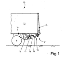
- Fig. 1 shows a vehicle, namely a truck 10.
- the truck 10 has a structure 11, which may be a so-called box body with a fully open back. The remaining walls of the structure may be formed closed.
- the back of the truck 10 is assigned a tail lift 12. Trained in the usual way tail lift 12 has a hoist 13, which on a chassis frame 14 of the truck 10th is arranged.
- the hoist 13 carries a loading platform 15, which in the in Fig. 1 shown closed position, the open back of the structure 11 completely closes.
- the hoist 13 has pivotally mounted on a transverse support tube 16 handlebar 17, which are pivotally connected to the loading platform 15.
- Pressure cylinder 18, in particular hydraulic cylinder, are used for pivoting the loading platform 15 about a horizontal axis of rotation.
- Further pressure cylinder 19, which are preferably also designed as a hydraulic cylinder, serve to raise and lower the loading platform 15.
- the loading platform 15 is thus mounted on the lifting mechanism 13 on the support tube 16, which in turn is associated with the chassis frame 14.
- the support tube 16 serving as a crossbeam has a preferably continuous cavity, so that lateral free ends 20 of the support tube 16 have openings 21. These openings 21 can each be closed by a specially designed sealing cap 22.
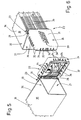
- the sealing cap 22 according to the invention consists of at least two parts, namely a first part for fixing the sealing cap 22 on the support tube 16 and a second part for closing the openings 21 in the region of the free ends 20 of the support tube 16.
- the first and the second part of the sealing cap 22nd are hinged together.
- the first part of the sealing cap 22 for attachment to the support tube 16 is referred to as a holding part 23.
- the second part of the sealing cap 22 for closing the openings 21 is referred to as cover 24.
- the lid 24 is pivotally connected in a lateral edge region with the holding part 23.
- a residual connection in particular a film hinge, is used for this purpose, which is designed in the manner of a line joint 25.
- the lid 24 is arranged in this way about the line joint 25 pivotally mounted on the holding part 23.
- the lid 24 can be pivoted about the hinge.
- the hinge-like connection can also be designed in other ways.
- the sealing cap 22 is formed from plastic, preferably a residual compound is used.
- the holding part 23 is fixed to a side surface 26 or side wall of the support tube 16.
- two fastening means 27 are used in the present case.
- the fastening means 27 may be releasable fastening means 27 such as screws or the like.
- rivet connections can also be used for fastening the holding part 23.
- adhesive bonds or the like come into question.
- the holding part 23 is arranged with the fastening means 27 directly at the free end 20 of the support tube 16, so that the holding part 23 and the free end 20 of the support tube 16 are arranged on the outside in alignment.
- the holding part 23 is approximately U-shaped in the embodiment shown, with a web 28 which extends completely over the side surface 26 of the support tube 16 and preferably rests against the outside of the support tube 16.
- two short flanges 29 are arranged or formed, respectively, which surround the support tube 16 at two opposite side surfaces 30.
- the holding part 23, the support tube 16 also enclose to a greater extent or completely.
- the pivotally mounted on the holding part 23 cover 24 consists of a top wall 31 and the edge thereof arranged collar walls 32, which together form a preferably circumferential collar.
- the cover 24 is adapted to the cross-sectional shape of the support tube 16 such that it closes the openings 21 in the region of the free ends 20 in a closed position.
- the collar walls 32 are for this purpose angled relative to the top wall 31, in the present embodiment by an angle of 90 °. In the closed position of the lid 24, the collar walls 32 bear against the outside on the side surfaces of the support tube 16. At least the collar walls 32 may be formed of a flexible plastic, so that a positive or sealing engagement on the outside of the support tube 16 is facilitated.
- a part of the collar is formed by the holding part 23.
- a recess 33 or notch is provided in the collar walls 32 of the lid 24, in which the holding part 23 is in the closed position of the lid 24 receiving.
- the collar or collar walls 32 are formed by the holding part 23.
- web-like projections 34 are further formed in the region of the collar walls 32, which can serve to stiffen the lid 24 and as a handle.
- a gripping tab 35 is additionally formed, which can likewise serve to grip the lid 24.
- a logo 39 of the manufacturer or an advertising imprint or the like is also applied, for example formed, in the exemplary embodiment shown.
- the lines 36 are used to connect the various control, display, control elements, hoists 23 and pressure cylinder 18, 19 with each other.
- the lines 36 lead to a control unit 37, which is arranged according to the invention in the support tube 16.
- control unit 37 may merely be a control box or distribution box, which may serve, for example, for wiring the individual components of the tail lift 12.
- control unit 37 may also include electronic and / or electrical components for controlling and / or regulating and / or displaying and / or controlling (all) functions of the tail lift 12.
- the control unit 37 is arranged on an inner side of the cover 24 or the cover wall 31, such that in a closed position of the cover 24 (FIG. Fig. 2 or 3) the control unit 37 is positioned in the support tube 16.
- the sealing cap 22 has a cable gland. This is formed in the region of the holding part 23.
- the web 28 of the holding part 23 has recesses 38 for this purpose.
- the recesses 38 are formed starting from a side surface of the web 28, as grooves or channels.
- the side surface of the web 28 is the surface facing the side surface 26 of the support tube 16.
- Fig. 7 shows, the lines 36 are laid parallel and spaced apart on the outside of the support tube 16.
- a separate recess 38 is provided in the holding part 23.
- several lines 36 can be passed through a single recess 38.
- the holding part 23 may be formed of a suitable, flexible plastic.
- a material with an increased flexibility may be present, so that not occupied by lines 36 recesses 38 can be sealed.
- special seals can be used.
- lines 36 extend through the recess 33 and notch in the collar walls 32 of the lid 24 and can be connected in this way to the control unit 37.
- the support tube 16 and the lid 24 have a matching, in the illustrated embodiment, substantially rectangular or square, cross-sectional shape.
- the sealing cap 22 according to the invention can also be adapted to other cross-sectional shapes of the support tube 16, for example to circular or oval cross-sections.
- the position of the hinge connection between the cover 24 and holding member 23 must be adjusted.
- the remainder of the connection or the like is arranged in the cover 24 and extends at a distance from the edge of the cover 24, so that it is pivotable against the support tube 16 for closing the opening 21.
Landscapes
- Engineering & Computer Science (AREA)
- Transportation (AREA)
- Mechanical Engineering (AREA)
- Seal Device For Vehicle (AREA)
- Gripping On Spindles (AREA)
- Paper (AREA)
- Vehicle Body Suspensions (AREA)
- Cooling, Air Intake And Gas Exhaust, And Fuel Tank Arrangements In Propulsion Units (AREA)
- Pressure Vessels And Lids Thereof (AREA)
- Loading And Unloading Of Fuel Tanks Or Ships (AREA)
- Closures For Containers (AREA)
- Flexible Shafts (AREA)
- Clamps And Clips (AREA)
Claims (12)
- Hayon élévateur destiné à être disposé sur un côté arrière d'un véhicule (10), comprenant un tube porteur (16) associé au véhicule (10) et servant à supporter une plate-forme de chargement (15), et comprenant des capuchons d'étanchéité pour fermer les extrémités ouvertes du tube porteur (16), caractérisé en ce qu'au moins un capuchon d'étanchéité (22) se compose d'au moins deux pièces connectées l'une à l'autre de manière articulée, notamment par charnière, une première pièce, notamment une pièce de fixation (23), pouvant être fixée sur le tube porteur (16) et présentant un passage pour au moins un câble (36) et la deuxième pièce, notamment un couvercle (24), étant réalisée pour fermer l'extrémité libre (20) du tube porteur (16) non couverte par la première pièce.
- Hayon élévateur selon la revendication 1, caractérisé en ce que la première pièce, notamment la pièce de fixation (23), peut être positionnée sur le tube porteur (16) au moins en partie en entourant ce dernier, notamment dans la région d'une extrémité libre (20) du tube porteur (16), la première pièce ou pièce de fixation (23) pouvant de préférence être fixée sur le tube porteur (16), notamment par vissage, collage ou rivetage.
- Hayon élévateur selon l'une quelconque des revendications précédentes, caractérisé en ce que la pièce de fixation (23) présente des évidements (38) et/ou des perçages pour permettre le passage des câbles (36), de préférence la pièce de fixation (23) est fabriquée au moins en partie en plastique pour fermer hermétiquement le passage de câbles, notamment seulement dans la région du passage de câbles.
- Hayon élévateur selon la revendication 3 ou l'une quelconque des revendications précédentes, caractérisé en ce que des évidements (38) sont disposés dans la région d'une surface latérale de la pièce de fixation (23) qui est tournée vers le tube porteur (16) lors de la fixation sur ce dernier.
- Hayon élévateur selon la revendication 1 ou l'une quelconque des revendications précédentes, caractérisé en ce que la deuxième pièce, notamment un couvercle (24), présente une forme adaptée à la forme du tube porteur, la deuxième pièce ou le couvercle (24) étant de préférence fixé(e) de manière pivotante sur la pièce de fixation (23) pour fermer une extrémité ouverte (20) du tube porteur (16).
- Hayon élévateur selon l'une quelconque des revendications précédentes, caractérisé en ce que le couvercle (24) pour la fermeture hermétique d'une extrémité ouverte (20) du tube porteur (16) est en plastique et/ou le couvercle (24), dans une position de fermeture, ferme du côté extérieur une extrémité ouverte (20) du tube porteur (16).
- Hayon élévateur selon l'une quelconque des revendications précédentes, caractérisé en ce que le couvercle (24) et la pièce de fixation (23) sont connectés l'un à l'autre par le biais d'une connexion résiduelle, notamment une charnière à film (25).
- Hayon élévateur selon l'une quelconque des revendications précédentes, caractérisé en ce que le couvercle (24) présente une paroi de couvercle (31) et un rebord périphérique façonné sur la paroi de couvercle (31), le rebord s'appliquant dans la position de fermeture de préférence complètement sur la périphérie du tube porteur (16), le rebord étant de préférence formé dans la position de fermeture du couvercle (24) au moins en partie par la pièce de fixation (23).
- Hayon élévateur selon l'une quelconque des revendications précédentes, caractérisé en ce que des composants électroniques, notamment pour commander des fonctions du hayon élévateur, sont disposés sur le couvercle (24) de telle sorte que les composants électroniques, lors du positionnement du couvercle (24) dans une position de fermeture pour recouvrir une extrémité ouverte (20) du tube porteur (16), soient disposés à l'intérieur du tube porteur (16).
- Hayon élévateur destiné à être disposé sur un côté arrière d'un véhicule (10), comprenant un tube porteur (16) associé au véhicule (10) et servant à supporter une plate-forme de chargement (15) selon l'une quelconque des revendications précédentes, caractérisé en ce qu'une unité de commande (37) est disposée dans le tube porteur (16).
- Hayon élévateur selon l'une quelconque des revendications précédentes, caractérisé en ce que l'unité de commande (37) est disposée dans la région d'extrémités libres (20) du tube porteur (16), de préférence est associée à un capuchon d'étanchéité (22) pour fermer des extrémités ouvertes (20) du tube porteur (16).
- Hayon élévateur selon l'une quelconque des revendications précédentes, caractérisé en ce que l'unité de commande (37) est disposée sur le capuchon d'étanchéité (22), notamment sur un couvercle (24) de celui-ci, de telle sorte que l'unité de commande (37) soit disposée à l'intérieur du tube porteur (16), dans une position de fermeture du couvercle (24) dans laquelle une extrémité libre (20) du tube porteur (16) associée au couvercle (24) est fermée par le capuchon d'étanchéité (22).
Applications Claiming Priority (2)
| Application Number | Priority Date | Filing Date | Title |
|---|---|---|---|
| DE20318124U | 2003-11-21 | ||
| DE20318124U DE20318124U1 (de) | 2003-11-21 | 2003-11-21 | Hubladebühne |
Publications (3)
| Publication Number | Publication Date |
|---|---|
| EP1533179A2 EP1533179A2 (fr) | 2005-05-25 |
| EP1533179A3 EP1533179A3 (fr) | 2007-02-14 |
| EP1533179B1 true EP1533179B1 (fr) | 2009-02-11 |
Family
ID=32010700
Family Applications (1)
| Application Number | Title | Priority Date | Filing Date |
|---|---|---|---|
| EP04025268A Expired - Lifetime EP1533179B1 (fr) | 2003-11-21 | 2004-10-23 | Hayon élévateur |
Country Status (3)
| Country | Link |
|---|---|
| EP (1) | EP1533179B1 (fr) |
| AT (1) | ATE422443T1 (fr) |
| DE (2) | DE20318124U1 (fr) |
Families Citing this family (3)
| Publication number | Priority date | Publication date | Assignee | Title |
|---|---|---|---|---|
| DE102006010262A1 (de) * | 2006-03-02 | 2007-09-13 | Gisela Weber | Montagesatz für eine Ladebordwand |
| DE102012013479A1 (de) * | 2012-07-09 | 2014-01-09 | Mbb Palfinger Gmbh | Hubladebühne |
| JP6378620B2 (ja) * | 2014-12-03 | 2018-08-22 | 極東開発工業株式会社 | パワーユニット装置及びパワーユニット装置を備えた荷受台昇降装置 |
Family Cites Families (5)
| Publication number | Priority date | Publication date | Assignee | Title |
|---|---|---|---|---|
| GB2040856A (en) * | 1979-01-23 | 1980-09-03 | Rich Services Inc Roy | Cable handling systems |
| DE3228765A1 (de) * | 1982-08-02 | 1984-02-02 | Emil Dautel GmbH, 7105 Leingarten | Hubladebuehne fuer lastfahrzeuge |
| BE1000012A6 (nl) * | 1987-02-03 | 1987-11-10 | Elskamp Hendrika Johanna Echtg | Inrichting voor het sturen van een laadplatform voor transportvoertuigen. |
| DE19500333C2 (de) * | 1995-01-07 | 1998-09-10 | Franz Henninghaus | Hydraulische Betätigungseinrichtung für Ladebordwände bei Fahrzeugen oder stationären Hubeinrichtungen |
| GB2312197B (en) * | 1996-04-17 | 1999-08-18 | Icl Systems Ab | Cable retraction mechanism |
-
2003
- 2003-11-21 DE DE20318124U patent/DE20318124U1/de not_active Expired - Lifetime
-
2004
- 2004-10-23 EP EP04025268A patent/EP1533179B1/fr not_active Expired - Lifetime
- 2004-10-23 DE DE502004008960T patent/DE502004008960D1/de not_active Expired - Lifetime
- 2004-10-23 AT AT04025268T patent/ATE422443T1/de active
Also Published As
| Publication number | Publication date |
|---|---|
| DE20318124U1 (de) | 2004-03-11 |
| ATE422443T1 (de) | 2009-02-15 |
| EP1533179A3 (fr) | 2007-02-14 |
| EP1533179A2 (fr) | 2005-05-25 |
| DE502004008960D1 (de) | 2009-03-26 |
Similar Documents
| Publication | Publication Date | Title |
|---|---|---|
| DE10313989B4 (de) | Kabeldurchführungsvorrichtung | |
| EP0937853B1 (fr) | Dispositif de commande pour une porte coulissante, en particulier pour véhicules | |
| EP1492967B1 (fr) | Robot comprenant un dispositif de guidage de lignes | |
| DE4337771C2 (de) | Hydraulischer Schwenkmotor | |
| DE1755643A1 (de) | Gelenkvorrichtung fuer Schwenktafeln,insbesondere Kraftfahrzeugtueren | |
| EP0838563A1 (fr) | Bras de distribution pour pompes à béton | |
| AT405748B (de) | Betätigungsanordnung für bewegliche teile an fahrzeugen | |
| DE19717041C1 (de) | Leitungsführung für ein Kraftfahrzeug | |
| EP1533179A2 (fr) | Hayon élévateur | |
| DE202015004305U1 (de) | Vorrichtung zum Öffnen und Schließen ein oder mehrerer Bugklappen, insbesondere für Schienenfahrzeuge | |
| EP0435172A1 (fr) | Dispositif pour la traversée d'une paroi et plaque de jonction pour celui-ci | |
| DE10142628A1 (de) | Verschluss- und Abdichtelement | |
| DE10034141A1 (de) | Kraftfahrzeug mit wenigstens einem klappbaren Karosserieteil | |
| DE19600260C1 (de) | Innenscharnier zur Unterbringung im Verschraubungskanal von Gehäusen | |
| DE9413475U1 (de) | Fahrtschreiber mit Mitteln zur geräteseitigen Befestigung eines den Geberleitungen zugeordneten Schutzrohres | |
| DE19508150C2 (de) | Elektrische Dose, insbesondere Verbindungsdose | |
| DE102007033169B4 (de) | Leitungsstrangübergang zwischen einem festen und einem beweglichen Karosserieteil an einem Fahrzeug | |
| DE3144725A1 (de) | "anordnung der innenbeleuchtung eines omnibusses an der dachinnenverkleidung des aufbaues" | |
| DE4413320A1 (de) | Anschlußglied für eine Energieführungskette | |
| EP0300210B1 (fr) | Fixation de tuyau | |
| DE10022448A1 (de) | Außenrückblickspiegel für Fahrzeuge, vorzugseise für Kraftfahrzeuge | |
| DE202006014963U1 (de) | Verschlusselement und Verschlussanordnung zum Verschließen einer Öffnung einer Kraftfahrzeugtür | |
| DE19845335A1 (de) | Geräteaufnahme für eine Unterflurgerätedose | |
| DE2438738C3 (de) | Einstellbare Bremsvorrichtung für ein Ausstellfenster in einem Fahrzeug | |
| EP1712117B1 (fr) | Epandeur agricole |
Legal Events
| Date | Code | Title | Description |
|---|---|---|---|
| PUAI | Public reference made under article 153(3) epc to a published international application that has entered the european phase |
Free format text: ORIGINAL CODE: 0009012 |
|
| AK | Designated contracting states |
Kind code of ref document: A2 Designated state(s): AT BE BG CH CY CZ DE DK EE ES FI FR GB GR HU IE IT LI LU MC NL PL PT RO SE SI SK TR |
|
| AX | Request for extension of the european patent |
Extension state: AL HR LT LV MK |
|
| PUAL | Search report despatched |
Free format text: ORIGINAL CODE: 0009013 |
|
| AK | Designated contracting states |
Kind code of ref document: A3 Designated state(s): AT BE BG CH CY CZ DE DK EE ES FI FR GB GR HU IE IT LI LU MC NL PL PT RO SE SI SK TR |
|
| AX | Request for extension of the european patent |
Extension state: AL HR LT LV MK |
|
| 17P | Request for examination filed |
Effective date: 20070810 |
|
| AKX | Designation fees paid |
Designated state(s): AT BE BG CH CY CZ DE DK EE ES FI FR GB GR HU IE IT LI LU MC NL PL PT RO SE SI SK TR |
|
| GRAP | Despatch of communication of intention to grant a patent |
Free format text: ORIGINAL CODE: EPIDOSNIGR1 |
|
| GRAS | Grant fee paid |
Free format text: ORIGINAL CODE: EPIDOSNIGR3 |
|
| RAP1 | Party data changed (applicant data changed or rights of an application transferred) |
Owner name: MBB PALFINGER GMBH |
|
| GRAA | (expected) grant |
Free format text: ORIGINAL CODE: 0009210 |
|
| AK | Designated contracting states |
Kind code of ref document: B1 Designated state(s): AT BE BG CH CY CZ DE DK EE ES FI FR GB GR HU IE IT LI LU MC NL PL PT RO SE SI SK TR |
|
| REG | Reference to a national code |
Ref country code: GB Ref legal event code: FG4D Free format text: NOT ENGLISH |
|
| REG | Reference to a national code |
Ref country code: CH Ref legal event code: EP |
|
| REG | Reference to a national code |
Ref country code: IE Ref legal event code: FG4D Free format text: LANGUAGE OF EP DOCUMENT: GERMAN |
|
| REF | Corresponds to: |
Ref document number: 502004008960 Country of ref document: DE Date of ref document: 20090326 Kind code of ref document: P |
|
| PG25 | Lapsed in a contracting state [announced via postgrant information from national office to epo] |
Ref country code: FI Free format text: LAPSE BECAUSE OF FAILURE TO SUBMIT A TRANSLATION OF THE DESCRIPTION OR TO PAY THE FEE WITHIN THE PRESCRIBED TIME-LIMIT Effective date: 20090211 Ref country code: ES Free format text: LAPSE BECAUSE OF FAILURE TO SUBMIT A TRANSLATION OF THE DESCRIPTION OR TO PAY THE FEE WITHIN THE PRESCRIBED TIME-LIMIT Effective date: 20090522 Ref country code: SI Free format text: LAPSE BECAUSE OF FAILURE TO SUBMIT A TRANSLATION OF THE DESCRIPTION OR TO PAY THE FEE WITHIN THE PRESCRIBED TIME-LIMIT Effective date: 20090211 Ref country code: NL Free format text: LAPSE BECAUSE OF FAILURE TO SUBMIT A TRANSLATION OF THE DESCRIPTION OR TO PAY THE FEE WITHIN THE PRESCRIBED TIME-LIMIT Effective date: 20090211 |
|
| NLV1 | Nl: lapsed or annulled due to failure to fulfill the requirements of art. 29p and 29m of the patents act | ||
| PG25 | Lapsed in a contracting state [announced via postgrant information from national office to epo] |
Ref country code: PL Free format text: LAPSE BECAUSE OF FAILURE TO SUBMIT A TRANSLATION OF THE DESCRIPTION OR TO PAY THE FEE WITHIN THE PRESCRIBED TIME-LIMIT Effective date: 20090211 Ref country code: SE Free format text: LAPSE BECAUSE OF FAILURE TO SUBMIT A TRANSLATION OF THE DESCRIPTION OR TO PAY THE FEE WITHIN THE PRESCRIBED TIME-LIMIT Effective date: 20090511 |
|
| REG | Reference to a national code |
Ref country code: IE Ref legal event code: FD4D |
|
| PG25 | Lapsed in a contracting state [announced via postgrant information from national office to epo] |
Ref country code: DK Free format text: LAPSE BECAUSE OF FAILURE TO SUBMIT A TRANSLATION OF THE DESCRIPTION OR TO PAY THE FEE WITHIN THE PRESCRIBED TIME-LIMIT Effective date: 20090211 Ref country code: PT Free format text: LAPSE BECAUSE OF FAILURE TO SUBMIT A TRANSLATION OF THE DESCRIPTION OR TO PAY THE FEE WITHIN THE PRESCRIBED TIME-LIMIT Effective date: 20090713 Ref country code: IE Free format text: LAPSE BECAUSE OF FAILURE TO SUBMIT A TRANSLATION OF THE DESCRIPTION OR TO PAY THE FEE WITHIN THE PRESCRIBED TIME-LIMIT Effective date: 20090211 Ref country code: CZ Free format text: LAPSE BECAUSE OF FAILURE TO SUBMIT A TRANSLATION OF THE DESCRIPTION OR TO PAY THE FEE WITHIN THE PRESCRIBED TIME-LIMIT Effective date: 20090211 Ref country code: EE Free format text: LAPSE BECAUSE OF FAILURE TO SUBMIT A TRANSLATION OF THE DESCRIPTION OR TO PAY THE FEE WITHIN THE PRESCRIBED TIME-LIMIT Effective date: 20090211 |
|
| PG25 | Lapsed in a contracting state [announced via postgrant information from national office to epo] |
Ref country code: RO Free format text: LAPSE BECAUSE OF FAILURE TO SUBMIT A TRANSLATION OF THE DESCRIPTION OR TO PAY THE FEE WITHIN THE PRESCRIBED TIME-LIMIT Effective date: 20090211 Ref country code: SK Free format text: LAPSE BECAUSE OF FAILURE TO SUBMIT A TRANSLATION OF THE DESCRIPTION OR TO PAY THE FEE WITHIN THE PRESCRIBED TIME-LIMIT Effective date: 20090211 |
|
| PLBE | No opposition filed within time limit |
Free format text: ORIGINAL CODE: 0009261 |
|
| STAA | Information on the status of an ep patent application or granted ep patent |
Free format text: STATUS: NO OPPOSITION FILED WITHIN TIME LIMIT |
|
| 26N | No opposition filed |
Effective date: 20091112 |
|
| PG25 | Lapsed in a contracting state [announced via postgrant information from national office to epo] |
Ref country code: BG Free format text: LAPSE BECAUSE OF FAILURE TO SUBMIT A TRANSLATION OF THE DESCRIPTION OR TO PAY THE FEE WITHIN THE PRESCRIBED TIME-LIMIT Effective date: 20090511 |
|
| BERE | Be: lapsed |
Owner name: MBB PALFINGER G.M.B.H. Effective date: 20091031 |
|
| PG25 | Lapsed in a contracting state [announced via postgrant information from national office to epo] |
Ref country code: MC Free format text: LAPSE BECAUSE OF NON-PAYMENT OF DUE FEES Effective date: 20091031 |
|
| REG | Reference to a national code |
Ref country code: CH Ref legal event code: PL |
|
| PG25 | Lapsed in a contracting state [announced via postgrant information from national office to epo] |
Ref country code: LI Free format text: LAPSE BECAUSE OF NON-PAYMENT OF DUE FEES Effective date: 20091031 Ref country code: BE Free format text: LAPSE BECAUSE OF NON-PAYMENT OF DUE FEES Effective date: 20091031 Ref country code: CH Free format text: LAPSE BECAUSE OF NON-PAYMENT OF DUE FEES Effective date: 20091031 Ref country code: GR Free format text: LAPSE BECAUSE OF FAILURE TO SUBMIT A TRANSLATION OF THE DESCRIPTION OR TO PAY THE FEE WITHIN THE PRESCRIBED TIME-LIMIT Effective date: 20090512 |
|
| PG25 | Lapsed in a contracting state [announced via postgrant information from national office to epo] |
Ref country code: IT Free format text: LAPSE BECAUSE OF FAILURE TO SUBMIT A TRANSLATION OF THE DESCRIPTION OR TO PAY THE FEE WITHIN THE PRESCRIBED TIME-LIMIT Effective date: 20090211 |
|
| PG25 | Lapsed in a contracting state [announced via postgrant information from national office to epo] |
Ref country code: LU Free format text: LAPSE BECAUSE OF NON-PAYMENT OF DUE FEES Effective date: 20091023 |
|
| PG25 | Lapsed in a contracting state [announced via postgrant information from national office to epo] |
Ref country code: HU Free format text: LAPSE BECAUSE OF FAILURE TO SUBMIT A TRANSLATION OF THE DESCRIPTION OR TO PAY THE FEE WITHIN THE PRESCRIBED TIME-LIMIT Effective date: 20090812 |
|
| PG25 | Lapsed in a contracting state [announced via postgrant information from national office to epo] |
Ref country code: TR Free format text: LAPSE BECAUSE OF FAILURE TO SUBMIT A TRANSLATION OF THE DESCRIPTION OR TO PAY THE FEE WITHIN THE PRESCRIBED TIME-LIMIT Effective date: 20090211 |
|
| PG25 | Lapsed in a contracting state [announced via postgrant information from national office to epo] |
Ref country code: CY Free format text: LAPSE BECAUSE OF FAILURE TO SUBMIT A TRANSLATION OF THE DESCRIPTION OR TO PAY THE FEE WITHIN THE PRESCRIBED TIME-LIMIT Effective date: 20090211 |
|
| PGFP | Annual fee paid to national office [announced via postgrant information from national office to epo] |
Ref country code: AT Payment date: 20131028 Year of fee payment: 10 |
|
| REG | Reference to a national code |
Ref country code: AT Ref legal event code: MM01 Ref document number: 422443 Country of ref document: AT Kind code of ref document: T Effective date: 20141023 |
|
| PG25 | Lapsed in a contracting state [announced via postgrant information from national office to epo] |
Ref country code: AT Free format text: LAPSE BECAUSE OF NON-PAYMENT OF DUE FEES Effective date: 20141023 |
|
| REG | Reference to a national code |
Ref country code: FR Ref legal event code: PLFP Year of fee payment: 12 |
|
| REG | Reference to a national code |
Ref country code: FR Ref legal event code: PLFP Year of fee payment: 13 |
|
| REG | Reference to a national code |
Ref country code: DE Ref legal event code: R082 Ref document number: 502004008960 Country of ref document: DE Representative=s name: MEISSNER BOLTE PATENTANWAELTE RECHTSANWAELTE P, DE Ref country code: DE Ref legal event code: R081 Ref document number: 502004008960 Country of ref document: DE Owner name: PALFINGER TAIL LIFTS GMBH, DE Free format text: FORMER OWNER: MBB PALFINGER GMBH, 27777 GANDERKESEE, DE |
|
| REG | Reference to a national code |
Ref country code: FR Ref legal event code: PLFP Year of fee payment: 14 |
|
| REG | Reference to a national code |
Ref country code: FR Ref legal event code: PLFP Year of fee payment: 15 |
|
| PGFP | Annual fee paid to national office [announced via postgrant information from national office to epo] |
Ref country code: GB Payment date: 20210930 Year of fee payment: 18 |
|
| PGFP | Annual fee paid to national office [announced via postgrant information from national office to epo] |
Ref country code: DE Payment date: 20210929 Year of fee payment: 18 |
|
| PGFP | Annual fee paid to national office [announced via postgrant information from national office to epo] |
Ref country code: FR Payment date: 20211018 Year of fee payment: 18 |
|
| REG | Reference to a national code |
Ref country code: DE Ref legal event code: R119 Ref document number: 502004008960 Country of ref document: DE |
|
| GBPC | Gb: european patent ceased through non-payment of renewal fee |
Effective date: 20221023 |
|
| PG25 | Lapsed in a contracting state [announced via postgrant information from national office to epo] |
Ref country code: FR Free format text: LAPSE BECAUSE OF NON-PAYMENT OF DUE FEES Effective date: 20221031 Ref country code: DE Free format text: LAPSE BECAUSE OF NON-PAYMENT OF DUE FEES Effective date: 20230503 |
|
| PG25 | Lapsed in a contracting state [announced via postgrant information from national office to epo] |
Ref country code: GB Free format text: LAPSE BECAUSE OF NON-PAYMENT OF DUE FEES Effective date: 20221023 |