EP1532913B1 - Dispositif d'amortissement de sièges de toilettes et/ou de couvercle de toilettes - Google Patents
Dispositif d'amortissement de sièges de toilettes et/ou de couvercle de toilettes Download PDFInfo
- Publication number
- EP1532913B1 EP1532913B1 EP04027382A EP04027382A EP1532913B1 EP 1532913 B1 EP1532913 B1 EP 1532913B1 EP 04027382 A EP04027382 A EP 04027382A EP 04027382 A EP04027382 A EP 04027382A EP 1532913 B1 EP1532913 B1 EP 1532913B1
- Authority
- EP
- European Patent Office
- Prior art keywords
- sleeve
- toilet
- damper
- toilet seat
- end piece
- Prior art date
- Legal status (The legal status is an assumption and is not a legal conclusion. Google has not performed a legal analysis and makes no representation as to the accuracy of the status listed.)
- Not-in-force
Links
Images


Classifications
-
- A—HUMAN NECESSITIES
- A47—FURNITURE; DOMESTIC ARTICLES OR APPLIANCES; COFFEE MILLS; SPICE MILLS; SUCTION CLEANERS IN GENERAL
- A47K—SANITARY EQUIPMENT NOT OTHERWISE PROVIDED FOR; TOILET ACCESSORIES
- A47K13/00—Seats or covers for all kinds of closets
- A47K13/10—Devices for raising and lowering, e.g. tilting or lifting mechanisms; Collapsible or rotating seats or covers
Definitions
- the invention relates to a device for damping a toilet seat or a toilet lid.
- the prior art offers a variety of damping devices.
- the DE 34 37 138 C2 discloses a damping device that is integrated directly into the rear end of a toilet seat and a toilet lid.
- the damping device is designed as a rotary damper and works with wings that displace a viscous fluid.
- the flow resistance causes a damping of the pivoting movement of the toilet seat or cover.
- dampers are already available in very small sizes.
- the diameter of commercially available dampers can be for example only 1 cm. Nevertheless, they offer sufficient cushioning and stability.
- the dampers are in the sanitary technology used in the production of toilet seat cover combinations as purchased parts.
- the toilet seat and cover combination according to the DE 100 51 805 A1 uses such a separate damper.
- the toilet seat has at its rear end to an integrally formed receptacle in which the damper is completely absorbed. On one side it protrudes into another receptacle of the toilet lid; on its other side, an adapter piece connects, which in turn protrudes from the receptacle and is in communication with a toilet bowl associated mounting pin.
- the known arrangement is very compact.
- the toilet seat and the toilet lid are mounted directly on the damper and the adapter.
- the damper and in particular the pivot of the damper are heavily loaded, especially when an actuation of the toilet lid, since the toilet lid is supported solely by the pin. This can lead to damage to the damper, to the escape of the damping fluid or even to a break of the pin and thus complete destruction of the damper.
- the danger is particularly great when closing in addition to the weight of the toilet lid (or toilet seat) a closing force, for example, by pressing down, added.
- the invention has for its object to provide a damping arrangement which is compact and moreover has an improved service life.
- the invention combines several advantages over conventional damper arrangements.
- a major advantage is the stability of the construction with minimal space requirements. This advantage is created by the damper at least partially surrounding sleeve. Occurring during closing transverse forces do not act - as in conventional solutions - directly on the sensitive pin of the damper, but are directed into the sleeve, and from there via the tail (and usually a mounting pin) in the toilet bowl.
- the damper itself remains largely unloaded in the direction transverse to the axis of rotation. A long life is the result.
- a further advantage of the invention lies in the ease of handling, in particular when the damper, the sleeve and the end piece can be joined together in one unit and the unit can be inserted into a receptacle in a toilet seat and / or a toilet lid, as appropriate.
- the combination of damper, sleeve and End piece can be made available to the end user pre-assembled. A mating of individual components on site can be omitted.
- the sleeve is preferably made of metal, for example stainless steel, or made of hard plastic.
- the sleeve has in its outer periphery a groove into which engages a circlip in the installed state, which serves to secure the sleeve in a receptacle of the toilet seat and / or toilet lid.
- a circlip in the installed state, which serves to secure the sleeve in a receptacle of the toilet seat and / or toilet lid.
- the circlip is not visible when installed. He sits, for example, in a recess in the toilet seat or cover, preferably directly at the joint between the toilet seat and toilet lid.
- the sleeve has a slot in its circumferential wall, through which a fastening pin engages in the end piece for securing the toilet lid or the toilet seat to the toilet bowl.
- the slot extends in the circumferential direction and prevents plug-in mounting pin slipping out of the tail of the sleeve.
- the end region of the device according to the invention is free in the fully assembled state and is accordingly visible in certain positions of the toilet seat or cover.
- the tail is inserted into the sleeve.
- This provides a particularly compact and aesthetically pleasing design, especially when the outer diameter of the end of the tail is adapted to the outer diameter of the sleeve.
- the tail will then be sleeve-like at least in one section. In both cases, a pin inserted through the slot can fix the end piece in the sleeve.
- Conventional dampers for damping rotary motion typically have at least one wing connected to the pivot which, upon rotation of the pivot, urges viscous fluid from one chamber to another chamber.
- the angle within which the pivot is movable is set, for example, to 110 °. If the specified working range is exceeded, the damper can be destroyed.
- the slot limits the opening and / or the closing movement of the toilet lid or the toilet seat. This eliminates the risk that the damper will be "over-tightened” and destroyed.
- the slot provides a stop that stops the movement of the toilet seat or the toilet lid before reaching the critical angular position of the damper.
- a structurally favorable solution is characterized in that for fixing to the mounting pin in the tail a screw is arranged, which can be reached through the slot.
- the screw can be a grub screw. In an end position of the toilet seat or cover, the screw is covered by the outer wall of the sleeve. In the other end position - preferably the open position - the screw is accessible.
- the sleeve expediently has on its outer circumference at least one profiled region which is in positive engagement with an associated region of the toilet seat or toilet lid.
- a development of the invention which is favorable in terms of good handleability is characterized in that the profiled area comprises at least one groove or a web or is formed as a flattening and that the associated area of the toilet seat or toilet lid acts as a web or groove or as Survey is formed. If the damping arrangement is not preassembled, for example, the damper and the sleeve is first inserted for mounting the entire device and the sleeve is "closed" by the end piece.
- the sleeve is then inserted together with the damper and the end piece as a compact unit in a integrally formed with the toilet seat or cover receptacle, wherein the grooves and webs ensure correct positioning of the unit in the circumferential direction. Furthermore, by the groove / webs a simple rotationally fixed connection can be created. Both the tail and the damper are easy and without the risk of misalignment mountable. The same applies, of course, when first the sleeve and then the damper is inserted.
- the arrangement according to the invention allows a pre-assembly as described above, with only the entire assembly needing to be inserted into the receptacle (s) later for final assembly.
- an O-ring may be provided between the tail and the inner wall of the sleeve.
- the O-ring prevents an already inserted end unintentionally released from the sleeve. Nevertheless, it offers only so much resistance that the tail can be easily removed to replace the damper.
- the invention can be used for damping, for example, only a lid.
- a common field of application is the simultaneous damping of toilet seat and toilet lid.
- a right-side and a left-side damper are required.
- the groove or the web of a sleeve offset from the groove or the web of the other sleeve It can be selected in each case a different angular distance.
- damping device is to be assigned to which side. Incidentally, a different cross-sectional configuration or width of the groove / webs is conceivable to uniquely determine the assignment.
- the correct positioning of the damping device in the circumferential direction plays an important role. It is suggested for a clear definition of the position that the Outer circumference of the sleeve is covered with at least two grooves or webs, which divide the outer periphery in different sized angle ranges. If, for example, two grooves are formed in the outer circumference, then the angular ranges should not be the same size, ie (idealized) 180 °, since otherwise two orientation possibilities of the damping device would be present.
- the tail protrudes into a sleeve receiving area of the toilet seat or the toilet lid.
- the sleeve receiving portion may be integrally formed at the rear end of the toilet seat or lid as described above.
- the tail needs to stand out only a small portion of the tab. Also, a stable arrangement is created by the largest possible attack area between the tail and the sleeve. The sometimes considerable lateral forces under load can thus be well absorbed.
- the sleeve can in principle be varied. It has to take up the end piece (turnable) on one side and lock on its other side the pin of the damper or its opposite end.
- a particularly simple design of the sleeve is characterized in that one end of the sleeve has a frontal end a recess which provides an opening to the interior of the sleeve and serves to receive one end of the damper.
- Commercially available dampers often have flattened ends, so that one will choose, for example, a recess running perpendicular to the damper axis, which is particularly easy to produce from the outside.
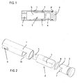
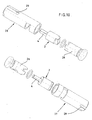
- the inventive device for damping a toilet seat or a toilet lid has according to FIG. 1 a first sleeve 1, a damper 2 received in the sleeve and a first end piece 3.
- the damper comprises a pin portion 4 and a cylinder portion 5 which is flattened at its end opposite the pin portion.
- the end piece 3 has a bore 6 into which a toilet bowl assigned (not shown) mounting pin can be inserted for attaching the device to a toilet bowl.
- a toilet bowl assigned (not shown) mounting pin can be inserted for attaching the device to a toilet bowl.
- the damper 3 At its side facing the damper 3 carries the tailpiece two web-like projections 7 which engage around the flattened portion of the cylinder 5 and thus holds the cylinder portion in the circumferential direction.
- an O-ring 8 is arranged, which fixes the end piece in the sleeve and prevents unwanted sliding out. As a rule, the O-ring 8 will be arranged in a groove 3 associated with the end piece.
- FIG. 2 shows the damping device after FIG. 1 in a perspective exploded view.
- the damper 2 is first inserted into the sleeve 1. He arrives with its pivot 4 in engagement with a formed in the sleeve complementary receiving portion 9, which is designed as a radial slot, which creates an opening to the interior of the sleeve.
- the pin 4 is thus always connected rotationally fixed to the sleeve 1.
- the end piece 3 is inserted together with the O-ring 8 in the sleeve 1, in such a way that the two web-like projections 7 engage around the flattened portion of the cylinder 5.
- an insertion of the end piece 3 together with already pre-assembled damper 2 in the sleeve 1 is possible. In any case, the assembly of the device according to the invention is very easy.
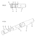
- FIGS. 3 and 4 show a second embodiment of the damping device according to the invention.
- the second embodiment has an end piece 11, the two webs 12 now comprise the pin 4 of the damper 2.
- the damper 2 is accommodated in a sleeve 13 which has a recess 14 in its end region, through which, when the damper 2 is plugged in, the flattened portion of the damper is non-rotatably connected to the sleeve 13.
- the cylinder portion 5 of the damper 2 rotates while the pin 4 is held by the end piece 11.
- FIG. 5 shows the first embodiment as a left-side damping device and the second embodiment as a right-side damping device.
- the tail with the cylinder portion 5 is engaged, while in the right-hand version of the pin 4 is encompassed by the webs 12 of the tail.
- Only schematically indicated are two integrally formed with a (not shown) toilet seat receptacles 14, 15 and two (also not shown) toilet cover associated receptacles 16, 17. Both the seat and the lid are in the closed position.
- the receptacle 17 assigned to the cover is in engagement with the sleeve 1.
- the sleeve 1 (and with the sleeve 1 also the pin 4) rotates.
- the cylinder section 5 the damper 2 remains stationary.
- the seat associated with the receptacle 15 slides in a pivoting of the seat on the sleeve 1 from.
- the receptacle 14 assigned to the seat is non-rotatably connected to the sleeve 13. If the seat is pivoted, the sleeve 13 rotates and takes the cylinder portion 5 of the damper, while the pin is held by the end piece 11.
- the lid receptacle 16 slides on pivoting of the lid on the sleeve 13 (the lid is, however, as described in the section previously damped on the left-side arrangement).
- a great advantage of the invention is that the damper used 2 - and in particular their pin 4 - are charged only in the direction of rotation.
- the z. T. considerable lateral forces are absorbed by the sleeve 1, 13 and passed over the end piece 3, 11 in the toilet bowl or ceramic.
- the life of the damper is significantly increased over comparable conventional designs.
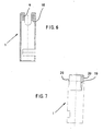
- FIGS. 6 and 7 show the sleeve 1 of the first embodiment in isolation.
- the damper rests against a stop 18 (see FIG FIG. 6 ), wherein the pin of the damper engages in the formed as a radial slot receiving portion 9 of the sleeve 1, which creates a breakthrough to the interior of the sleeve.
- the sleeve 1 has on its outer side a groove 19 which allows an accurate positioning of the sleeve - and thus of the damper.
- the groove 19 engages an associated in one of the receptacles 15 or 17 trained web. It can also be provided several grooves / webs. Although the grooves / webs with suitable training for transfer provide the torque required positive rotational engagement, but their task is primarily in the positioning of the sleeve.
- the actual engagement for power transmission creates a flattening 20, which is formed by the formed as a radial slot receiving portion 9. In the flat 20 engages a (not shown) the toilet seat or toilet cover associated web.
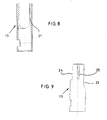
- FIGS. 8 and 9 show the sleeve of the second embodiment in isolation.
- the damper (not shown) is located on a stop 21 (see FIG. 8 ), wherein the flattened portion of the cylinder portion of the damper engages in the formed as a radial slot receiving portion of the sleeve 13, which creates an opening to the interior of the sleeve.
- On the outside of the sleeve one or more grooves 22 are formed, engage in the associated formed in one of the receptacles 14 or 16 webs. If the grooves 19 and 21 are distributed differently over the outer circumference of the sleeve, a safeguard against insertion of the sleeve in the wrong side can be avoided.
- a different cross-sectional shape or width of the groove and webs can have the same effect.
- the actual power transmission takes place via a flattening 23 and optionally via an opposite flattening 24 into which a web 25 of the toilet seat (see the right-side damper arrangement in FIG. 5 ) or a web of the toilet lid engages.
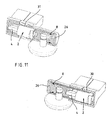
- FIG. 10 shows a further pair of damping devices according to the invention in an exploded perspective view, which is adapted to another form of damper 2.
- the left-side damping device arranged in the figure above and the right-side damping device have identical end pieces 26.
- the two sleeves 27 and 28 are also formed with sleeve ends open on both sides, wherein the sleeve 27 receives the pin 4 opposite portion of the damper, while the sleeve 28 defines the pin 4.
- grooves 29 are formed, which with webs 30 (see FIG. 11 ) are engaged. It is steamed the toilet lid. The recording associated with the toilet ring slides on a pivoting movement on the sleeve.
- FIG. 11 shows both damping devices mounted.
- FIG. 12 Referring to the in a sectional view of an embodiment similar to that of FIG. 1 is shown. Between an end piece 32 and a sleeve 33 of the damper 2 is received, wherein two webs 341 engage around the flattened portion of the cylinder 5. The sleeve 33 is engaged with the pin 4 of the damper 2 and thus creates a rotationally fixed connection. In the outer wall of the sleeve 33, a groove 34 is formed, in which a (not shown) retaining ring is inserted, which is a sliding out of the unit 33, damper 2 and end piece 32 from the receptacle of the (not shown) toilet seat or Toilet lids prevented. The retaining ring is placed in a recess in the toilet seat or in the toilet lid, preferably in the region of the joint.
- FIGS. 13 to 15 is for fixing the tail on a mounting pin a screw 35 is provided, which is screwed radially into the end piece. From the FIGS. 14 and 15 It is clear that the screw is accessible even when the end piece, via a slot 36 which limits the rotational movement of the sleeve 33 when the fastening pin is inserted.
- the screw 35 is screwed so far into the tailpiece for attachment to the mounting pin that the sleeve can slide freely on the tail.
- FIGS. 16 to 19 show a the embodiment according to FIGS. 12 to 15 configured embodiment, but in the present case a right-side damping device.
- the device according to the invention can be completely integrated in the receptacle.
- the arrangement can be made so that only the end of the tail is visible.
- the end piece may be directly formed with a pin and e.g. be connected via a bayonet-type closure with the sleeve.
- the mounting hole shown corresponds to the rule.
- the device according to the invention can be used both as a right-side and as a left-side damping device and is not limited to the illustrated shape of the receptacles of the seat and lid.
Claims (15)
- Dispositif pour vaporiser un siège de toilettes ou un couvercle de toilettes, avec- un vaporisateur (2), qui présente une première extrémité et une seconde extrémité pouvant tourner par rapport à la première extrémité,- un manchon (1 ; 13 ; 33) pour recevoir le vaporisateur (2), lequel vaporisateur est en prise, par sa première ou sa seconde extrémité, avec le manchon de manière solidaire en rotation, et- une partie d'extrémité (3 ; 11 ; 32), qui est raccordée à rotation au manchon (1 ; 13 ; 33) et est en prise de manière solidaire en rotation avec l'autre extrémité du vaporisateur (2),- dans lequel la partie d'extrémité (3 ; 11 ; 32) peut être reliée à une cuvette de toilettes affectée au siège de toilettes et/ou au couvercle de toilettes et- le siège de toilettes ou le couvercle de toilettes peut être relié au manchon (1 ; 13 ; 33) de manière solidaire en rotation.
- Dispositif selon la revendication 1, caractérisé en ce que le vaporisateur, le manchon (1 ; 13 ; 33) et la partie d'extrémité (3 ; 11 ; 32) peuvent être assemblés pour former une unité et l'unité peut être emboîtée dans un logement d'un siège de toilettes et/ou d'un couvercle de toilettes.
- Dispositif selon la revendication 1 ou 2, caractérisé en ce que le manchon (1 ; 13 ; 33) présente une rainure (34) sur sa périphérie externe et en ce qu'un anneau de sécurité, qui sert à bloquer le manchon dans un logement du siège de toilettes et/ou du couvercle de toilettes, s'engage à l'état encastré dans la rainure.
- Dispositif selon l'une quelconque des revendications 1 à 3, caractérisé en ce que le manchon (1 ; 13 ; 33) présente dans sa paroi périphérique une fente (10 ; 36), à travers laquelle s'engage un tenon de fixation dans la partie d'extrémité (3 ; 11 ; 32) pour fixer le couvercle de toilettes ou le siège de toilettes sur la cuvette de toilettes.
- Dispositif selon la revendication 4, caractérisé en ce que la fente (10 ; 36) limite le mouvement d'ouverture et/ou de fermeture du couvercle de toilettes ou du siège de toilettes.
- Dispositif selon la revendication 4 ou 5, caractérisé en ce que la partie d'extrémité (3 ; 11 ; 32) peut être fixée sur le tenon de fixation.
- Dispositif selon la revendication 6, caractérisé en ce que, pour la fixation sur le tenon de fixation dans la partie d'extrémité (3 ; 11 ; 32), on agence une vis (35), qui peut être atteinte à travers la fente (10 ; 36).
- Dispositif selon l'une quelconque des revendications 1 à 7, caractérisé en ce que le manchon (1 ; 13 ; 33) présente, sur sa périphérie externe, au moins une zone profilée, qui est en prise par adaptation de forme avec une zone correspondante du siège de toilettes ou du couvercle de toilettes.
- Dispositif selon la revendication 8, caractérisé en ce que la zone profilée comprend au moins une rainure (19 ; 22) ou une nervure ou se présente sous la forme d'un méplat (20 ; 23 ; 24) et en ce que la zone correspondante du siège de toilettes ou du couvercle de toilettes se présente sous la forme d'une nervure ou d'une rainure ou sous la forme d'une surélévation (25).
- Dispositif selon la revendication 9, caractérisé en ce que, lors de l'utilisation d'un vaporisateur du côté droit ou du côté gauche, les rainures (19) ou les nervures du premier manchon (1) sont agencées de manière décalée par rapport aux rainures (22) ou aux nervures de l'autre manchon (13).
- Dispositif selon l'une quelconque des revendications 8 à 10, caractérisé en ce que le manchon présente au moins deux rainures (19 ; 22) ou nervures, qui subdivisent la périphérie externe du manchon (1 ; 13 ; 33) en deux zones angulaires différentes.
- Dispositif selon l'une quelconque des revendications 1 à 11, caractérisé en ce que la partie d'extrémité (3 ; 11 ; 32) s'enfonce jusque dans une zone réceptrice du manchon du siège de toilettes ou du couvercle de toilettes.
- Dispositif selon l'une quelconque des revendications 1 à 12, caractérisé en ce qu'une extrémité du manchon (1 ; 13 ; 32) présente, sur son côté frontal, un évidement (9 ; 14), qui crée une ouverture vers l'intérieur du manchon et qui sert à recevoir une extrémité (4) du vaporisateur (2).
- Dispositif selon l'une quelconque des revendications 1 à 13, caractérisé en ce que l'on prévoit un anneau torique (8) entre la partie d'extrémité (3 ; 11 ; 32) et la paroi interne du manchon.
- Combinaison de siège-couvercle de toilettes avec au moins un dispositif de vaporisation selon l'une quelconque des revendications 1 à 14.
Applications Claiming Priority (2)
| Application Number | Priority Date | Filing Date | Title |
|---|---|---|---|
| DE10353944A DE10353944B4 (de) | 2003-11-18 | 2003-11-18 | Einrichtung zum Dämpfen eines WC-Sitzes oder eines WC-Deckels |
| DE10353944 | 2003-11-18 |
Publications (3)
| Publication Number | Publication Date |
|---|---|
| EP1532913A2 EP1532913A2 (fr) | 2005-05-25 |
| EP1532913A3 EP1532913A3 (fr) | 2006-04-19 |
| EP1532913B1 true EP1532913B1 (fr) | 2008-06-04 |
Family
ID=34428792
Family Applications (1)
| Application Number | Title | Priority Date | Filing Date |
|---|---|---|---|
| EP04027382A Not-in-force EP1532913B1 (fr) | 2003-11-18 | 2004-11-18 | Dispositif d'amortissement de sièges de toilettes et/ou de couvercle de toilettes |
Country Status (3)
| Country | Link |
|---|---|
| EP (1) | EP1532913B1 (fr) |
| AT (1) | ATE397407T1 (fr) |
| DE (2) | DE10353944B4 (fr) |
Families Citing this family (5)
| Publication number | Priority date | Publication date | Assignee | Title |
|---|---|---|---|---|
| DE102004029419B4 (de) * | 2004-06-18 | 2011-04-28 | Hamberger Industriewerke Gmbh | WC-Sitzgelenk und WC-Sitzgarnitur |
| WO2008031254A1 (fr) * | 2006-08-16 | 2008-03-20 | Pinhua Gong | Support de fixation pour abattant de cuvette de w.-c. |
| ITMI20071193A1 (it) * | 2007-06-13 | 2008-12-14 | Cavagna & Sipex Internat S R L | Dispositivo frenante interponibile tra elementi reciprocamente ruotabili. |
| WO2012092930A2 (fr) | 2011-01-03 | 2012-07-12 | Pressalit A/S | Agencement de charnière de toilettes |
| DE102019105939B4 (de) * | 2018-10-08 | 2022-06-30 | Hamberger Industriewerke Gmbh | Rotationsdämpfer und WC-Sitzgarnitur |
Family Cites Families (5)
| Publication number | Priority date | Publication date | Assignee | Title |
|---|---|---|---|---|
| DE3437138C2 (de) * | 1984-10-10 | 1986-10-30 | Pag Presswerk Ag, 4300 Essen | Toilettenabdeckung mit Dämpfungselementen |
| DE10051805B4 (de) * | 2000-10-18 | 2005-04-14 | Hamberger Industriewerke Gmbh | WC-Sitzgelenk |
| JP2003176845A (ja) * | 2001-12-12 | 2003-06-27 | Sankyo Seiki Mfg Co Ltd | ダンパー装置 |
| DE20215330U1 (de) * | 2002-04-23 | 2002-12-19 | Asem Industrieberatung Und Ver | Befestigungsvorrichtung für die Absenkung einer Toilettenabdeckung mit Schnellbefestigung |
| DE10324172A1 (de) * | 2002-05-27 | 2003-12-11 | Mkw Iot Metall Kunststoff Und | Gelenk |
-
2003
- 2003-11-18 DE DE10353944A patent/DE10353944B4/de not_active Expired - Fee Related
-
2004
- 2004-11-18 EP EP04027382A patent/EP1532913B1/fr not_active Not-in-force
- 2004-11-18 AT AT04027382T patent/ATE397407T1/de not_active IP Right Cessation
- 2004-11-18 DE DE502004007312T patent/DE502004007312D1/de active Active
Also Published As
| Publication number | Publication date |
|---|---|
| ATE397407T1 (de) | 2008-06-15 |
| DE10353944A1 (de) | 2005-06-23 |
| EP1532913A3 (fr) | 2006-04-19 |
| EP1532913A2 (fr) | 2005-05-25 |
| DE10353944B4 (de) | 2007-08-09 |
| DE502004007312D1 (de) | 2008-07-17 |
Similar Documents
| Publication | Publication Date | Title |
|---|---|---|
| EP1290303B1 (fr) | Serrure a barres pour systeme de fermeture | |
| EP2286048B1 (fr) | Dispositif amortisseur pour portes de meubles | |
| EP3615749B1 (fr) | Ferrure pour fênetre ou porte | |
| DE10333925A1 (de) | Möbelscharnier mit Öffnungsautomatik, insbesondere für Möbeltüren | |
| DE102011051553B4 (de) | Beschlag für Fenster oder Türen | |
| EP2147179B1 (fr) | Amortisseur à butée | |
| EP3336284B1 (fr) | Corps de butée pour poignée d'actionnement, poignée d'actionnement et porte | |
| DE102008025265A1 (de) | Faltdeckel | |
| CH644666A5 (de) | Scharnier. | |
| WO2000014371A1 (fr) | Charniere a visser comportant une position d'arret | |
| DE2916242A1 (de) | Sicherheitsanordnung fuer tueren, fenster o.dgl. | |
| EP1532913B1 (fr) | Dispositif d'amortissement de sièges de toilettes et/ou de couvercle de toilettes | |
| EP2873787A2 (fr) | Maniement d'actionnement | |
| EP1659250B1 (fr) | Fenêtre, porte ou analogue avec un renvoi de coin | |
| EP0228527B1 (fr) | Ferrure pour portes et fenêtres | |
| DE102007003789A1 (de) | Sicherungselement | |
| EP1967111A2 (fr) | Dispositif d'amortissement | |
| DE19932443C2 (de) | Scharnier | |
| EP3363969B1 (fr) | Poignée d'actionnement | |
| EP0036141B1 (fr) | Dispositif d'arrêt actionné par une clé | |
| EP1599650B1 (fr) | Dispositif de fermeture pour portes d'appareils de cuisines industrielles | |
| EP0861953B1 (fr) | Poignée de manoeuvre | |
| DE102007010930A1 (de) | Dämpfungseinrichtung | |
| EP2284342A2 (fr) | Charnière avec surface d'appui encochée | |
| DE202007003368U1 (de) | Dämpfungseinrichtung |
Legal Events
| Date | Code | Title | Description |
|---|---|---|---|
| PUAI | Public reference made under article 153(3) epc to a published international application that has entered the european phase |
Free format text: ORIGINAL CODE: 0009012 |
|
| AK | Designated contracting states |
Kind code of ref document: A2 Designated state(s): AT BE BG CH CY CZ DE DK EE ES FI FR GB GR HU IE IS IT LI LU MC NL PL PT RO SE SI SK TR |
|
| AX | Request for extension of the european patent |
Extension state: AL HR LT LV MK YU |
|
| PUAL | Search report despatched |
Free format text: ORIGINAL CODE: 0009013 |
|
| AK | Designated contracting states |
Kind code of ref document: A3 Designated state(s): AT BE BG CH CY CZ DE DK EE ES FI FR GB GR HU IE IS IT LI LU MC NL PL PT RO SE SI SK TR |
|
| AX | Request for extension of the european patent |
Extension state: AL HR LT LV MK YU |
|
| 17P | Request for examination filed |
Effective date: 20060904 |
|
| AKX | Designation fees paid |
Designated state(s): AT BE BG CH CY CZ DE DK EE ES FI FR GB GR HU IE IS IT LI LU MC NL PL PT RO SE SI SK TR |
|
| GRAP | Despatch of communication of intention to grant a patent |
Free format text: ORIGINAL CODE: EPIDOSNIGR1 |
|
| GRAS | Grant fee paid |
Free format text: ORIGINAL CODE: EPIDOSNIGR3 |
|
| RAP1 | Party data changed (applicant data changed or rights of an application transferred) |
Owner name: PAGETTE GMBH |
|
| GRAA | (expected) grant |
Free format text: ORIGINAL CODE: 0009210 |
|
| AK | Designated contracting states |
Kind code of ref document: B1 Designated state(s): AT BE BG CH CY CZ DE DK EE ES FI FR GB GR HU IE IS IT LI LU MC NL PL PT RO SE SI SK TR |
|
| REG | Reference to a national code |
Ref country code: GB Ref legal event code: FG4D Free format text: NOT ENGLISH |
|
| REG | Reference to a national code |
Ref country code: CH Ref legal event code: EP |
|
| REF | Corresponds to: |
Ref document number: 502004007312 Country of ref document: DE Date of ref document: 20080717 Kind code of ref document: P |
|
| REG | Reference to a national code |
Ref country code: IE Ref legal event code: FG4D Free format text: LANGUAGE OF EP DOCUMENT: GERMAN |
|
| PG25 | Lapsed in a contracting state [announced via postgrant information from national office to epo] |
Ref country code: ES Free format text: LAPSE BECAUSE OF FAILURE TO SUBMIT A TRANSLATION OF THE DESCRIPTION OR TO PAY THE FEE WITHIN THE PRESCRIBED TIME-LIMIT Effective date: 20080915 Ref country code: FI Free format text: LAPSE BECAUSE OF FAILURE TO SUBMIT A TRANSLATION OF THE DESCRIPTION OR TO PAY THE FEE WITHIN THE PRESCRIBED TIME-LIMIT Effective date: 20080604 Ref country code: SI Free format text: LAPSE BECAUSE OF FAILURE TO SUBMIT A TRANSLATION OF THE DESCRIPTION OR TO PAY THE FEE WITHIN THE PRESCRIBED TIME-LIMIT Effective date: 20080604 |
|
| PG25 | Lapsed in a contracting state [announced via postgrant information from national office to epo] |
Ref country code: PL Free format text: LAPSE BECAUSE OF FAILURE TO SUBMIT A TRANSLATION OF THE DESCRIPTION OR TO PAY THE FEE WITHIN THE PRESCRIBED TIME-LIMIT Effective date: 20080604 |
|
| NLT1 | Nl: modifications of names registered in virtue of documents presented to the patent office pursuant to art. 16 a, paragraph 1 |
Owner name: TOTO GERMANY GMBH |
|
| REG | Reference to a national code |
Ref country code: IE Ref legal event code: FD4D |
|
| PG25 | Lapsed in a contracting state [announced via postgrant information from national office to epo] |
Ref country code: IS Free format text: LAPSE BECAUSE OF FAILURE TO SUBMIT A TRANSLATION OF THE DESCRIPTION OR TO PAY THE FEE WITHIN THE PRESCRIBED TIME-LIMIT Effective date: 20081004 Ref country code: CZ Free format text: LAPSE BECAUSE OF FAILURE TO SUBMIT A TRANSLATION OF THE DESCRIPTION OR TO PAY THE FEE WITHIN THE PRESCRIBED TIME-LIMIT Effective date: 20080604 Ref country code: IE Free format text: LAPSE BECAUSE OF FAILURE TO SUBMIT A TRANSLATION OF THE DESCRIPTION OR TO PAY THE FEE WITHIN THE PRESCRIBED TIME-LIMIT Effective date: 20080604 Ref country code: SE Free format text: LAPSE BECAUSE OF FAILURE TO SUBMIT A TRANSLATION OF THE DESCRIPTION OR TO PAY THE FEE WITHIN THE PRESCRIBED TIME-LIMIT Effective date: 20080904 Ref country code: PT Free format text: LAPSE BECAUSE OF FAILURE TO SUBMIT A TRANSLATION OF THE DESCRIPTION OR TO PAY THE FEE WITHIN THE PRESCRIBED TIME-LIMIT Effective date: 20081104 |
|
| RAP2 | Party data changed (patent owner data changed or rights of a patent transferred) |
Owner name: TOTO GERMANY GMBH |
|
| PG25 | Lapsed in a contracting state [announced via postgrant information from national office to epo] |
Ref country code: SK Free format text: LAPSE BECAUSE OF FAILURE TO SUBMIT A TRANSLATION OF THE DESCRIPTION OR TO PAY THE FEE WITHIN THE PRESCRIBED TIME-LIMIT Effective date: 20080604 Ref country code: RO Free format text: LAPSE BECAUSE OF FAILURE TO SUBMIT A TRANSLATION OF THE DESCRIPTION OR TO PAY THE FEE WITHIN THE PRESCRIBED TIME-LIMIT Effective date: 20080604 |
|
| PLBE | No opposition filed within time limit |
Free format text: ORIGINAL CODE: 0009261 |
|
| STAA | Information on the status of an ep patent application or granted ep patent |
Free format text: STATUS: NO OPPOSITION FILED WITHIN TIME LIMIT |
|
| PG25 | Lapsed in a contracting state [announced via postgrant information from national office to epo] |
Ref country code: BG Free format text: LAPSE BECAUSE OF FAILURE TO SUBMIT A TRANSLATION OF THE DESCRIPTION OR TO PAY THE FEE WITHIN THE PRESCRIBED TIME-LIMIT Effective date: 20080904 Ref country code: DK Free format text: LAPSE BECAUSE OF FAILURE TO SUBMIT A TRANSLATION OF THE DESCRIPTION OR TO PAY THE FEE WITHIN THE PRESCRIBED TIME-LIMIT Effective date: 20080604 Ref country code: EE Free format text: LAPSE BECAUSE OF FAILURE TO SUBMIT A TRANSLATION OF THE DESCRIPTION OR TO PAY THE FEE WITHIN THE PRESCRIBED TIME-LIMIT Effective date: 20080604 |
|
| NLT2 | Nl: modifications (of names), taken from the european patent patent bulletin |
Owner name: TOTO GERMANY GMBH Effective date: 20090218 |
|
| 26N | No opposition filed |
Effective date: 20090305 |
|
| REG | Reference to a national code |
Ref country code: FR Ref legal event code: CD |
|
| BERE | Be: lapsed |
Owner name: PAGETTE G.M.B.H. Effective date: 20081130 |
|
| PG25 | Lapsed in a contracting state [announced via postgrant information from national office to epo] |
Ref country code: MC Free format text: LAPSE BECAUSE OF NON-PAYMENT OF DUE FEES Effective date: 20081130 |
|
| REG | Reference to a national code |
Ref country code: CH Ref legal event code: PL |
|
| PG25 | Lapsed in a contracting state [announced via postgrant information from national office to epo] |
Ref country code: BE Free format text: LAPSE BECAUSE OF NON-PAYMENT OF DUE FEES Effective date: 20081130 |
|
| PG25 | Lapsed in a contracting state [announced via postgrant information from national office to epo] |
Ref country code: LI Free format text: LAPSE BECAUSE OF NON-PAYMENT OF DUE FEES Effective date: 20081130 Ref country code: CH Free format text: LAPSE BECAUSE OF NON-PAYMENT OF DUE FEES Effective date: 20081130 |
|
| PG25 | Lapsed in a contracting state [announced via postgrant information from national office to epo] |
Ref country code: AT Free format text: LAPSE BECAUSE OF NON-PAYMENT OF DUE FEES Effective date: 20081118 |
|
| PG25 | Lapsed in a contracting state [announced via postgrant information from national office to epo] |
Ref country code: CY Free format text: LAPSE BECAUSE OF FAILURE TO SUBMIT A TRANSLATION OF THE DESCRIPTION OR TO PAY THE FEE WITHIN THE PRESCRIBED TIME-LIMIT Effective date: 20080604 Ref country code: LU Free format text: LAPSE BECAUSE OF NON-PAYMENT OF DUE FEES Effective date: 20081118 Ref country code: HU Free format text: LAPSE BECAUSE OF FAILURE TO SUBMIT A TRANSLATION OF THE DESCRIPTION OR TO PAY THE FEE WITHIN THE PRESCRIBED TIME-LIMIT Effective date: 20081205 |
|
| PG25 | Lapsed in a contracting state [announced via postgrant information from national office to epo] |
Ref country code: TR Free format text: LAPSE BECAUSE OF FAILURE TO SUBMIT A TRANSLATION OF THE DESCRIPTION OR TO PAY THE FEE WITHIN THE PRESCRIBED TIME-LIMIT Effective date: 20080604 |
|
| PG25 | Lapsed in a contracting state [announced via postgrant information from national office to epo] |
Ref country code: GR Free format text: LAPSE BECAUSE OF FAILURE TO SUBMIT A TRANSLATION OF THE DESCRIPTION OR TO PAY THE FEE WITHIN THE PRESCRIBED TIME-LIMIT Effective date: 20080905 |
|
| PGFP | Annual fee paid to national office [announced via postgrant information from national office to epo] |
Ref country code: FR Payment date: 20101130 Year of fee payment: 7 |
|
| PGFP | Annual fee paid to national office [announced via postgrant information from national office to epo] |
Ref country code: IT Payment date: 20101125 Year of fee payment: 7 Ref country code: GB Payment date: 20101118 Year of fee payment: 7 |
|
| GBPC | Gb: european patent ceased through non-payment of renewal fee |
Effective date: 20111118 |
|
| REG | Reference to a national code |
Ref country code: FR Ref legal event code: ST Effective date: 20120731 |
|
| PG25 | Lapsed in a contracting state [announced via postgrant information from national office to epo] |
Ref country code: IT Free format text: LAPSE BECAUSE OF NON-PAYMENT OF DUE FEES Effective date: 20111118 |
|
| PG25 | Lapsed in a contracting state [announced via postgrant information from national office to epo] |
Ref country code: GB Free format text: LAPSE BECAUSE OF NON-PAYMENT OF DUE FEES Effective date: 20111118 |
|
| PG25 | Lapsed in a contracting state [announced via postgrant information from national office to epo] |
Ref country code: FR Free format text: LAPSE BECAUSE OF NON-PAYMENT OF DUE FEES Effective date: 20111130 |
|
| PGFP | Annual fee paid to national office [announced via postgrant information from national office to epo] |
Ref country code: DE Payment date: 20151130 Year of fee payment: 12 |
|
| PGFP | Annual fee paid to national office [announced via postgrant information from national office to epo] |
Ref country code: NL Payment date: 20151118 Year of fee payment: 12 |
|
| REG | Reference to a national code |
Ref country code: DE Ref legal event code: R119 Ref document number: 502004007312 Country of ref document: DE |
|
| REG | Reference to a national code |
Ref country code: NL Ref legal event code: MM Effective date: 20161201 |
|
| PG25 | Lapsed in a contracting state [announced via postgrant information from national office to epo] |
Ref country code: NL Free format text: LAPSE BECAUSE OF NON-PAYMENT OF DUE FEES Effective date: 20161201 |
|
| PG25 | Lapsed in a contracting state [announced via postgrant information from national office to epo] |
Ref country code: DE Free format text: LAPSE BECAUSE OF NON-PAYMENT OF DUE FEES Effective date: 20170601 |