EP1532913B1 - Device for damping toilet seats and/or toilet covers - Google Patents
Device for damping toilet seats and/or toilet covers Download PDFInfo
- Publication number
- EP1532913B1 EP1532913B1 EP04027382A EP04027382A EP1532913B1 EP 1532913 B1 EP1532913 B1 EP 1532913B1 EP 04027382 A EP04027382 A EP 04027382A EP 04027382 A EP04027382 A EP 04027382A EP 1532913 B1 EP1532913 B1 EP 1532913B1
- Authority
- EP
- European Patent Office
- Prior art keywords
- sleeve
- toilet
- damper
- toilet seat
- end piece
- Prior art date
- Legal status (The legal status is an assumption and is not a legal conclusion. Google has not performed a legal analysis and makes no representation as to the accuracy of the status listed.)
- Not-in-force
Links
Images


Classifications
-
- A—HUMAN NECESSITIES
- A47—FURNITURE; DOMESTIC ARTICLES OR APPLIANCES; COFFEE MILLS; SPICE MILLS; SUCTION CLEANERS IN GENERAL
- A47K—SANITARY EQUIPMENT NOT OTHERWISE PROVIDED FOR; TOILET ACCESSORIES
- A47K13/00—Seats or covers for all kinds of closets
- A47K13/10—Devices for raising and lowering, e.g. tilting or lifting mechanisms; Collapsible or rotating seats or covers
Definitions
- the invention relates to a device for damping a toilet seat or a toilet lid.
- the prior art offers a variety of damping devices.
- the DE 34 37 138 C2 discloses a damping device that is integrated directly into the rear end of a toilet seat and a toilet lid.
- the damping device is designed as a rotary damper and works with wings that displace a viscous fluid.
- the flow resistance causes a damping of the pivoting movement of the toilet seat or cover.
- dampers are already available in very small sizes.
- the diameter of commercially available dampers can be for example only 1 cm. Nevertheless, they offer sufficient cushioning and stability.
- the dampers are in the sanitary technology used in the production of toilet seat cover combinations as purchased parts.
- the toilet seat and cover combination according to the DE 100 51 805 A1 uses such a separate damper.
- the toilet seat has at its rear end to an integrally formed receptacle in which the damper is completely absorbed. On one side it protrudes into another receptacle of the toilet lid; on its other side, an adapter piece connects, which in turn protrudes from the receptacle and is in communication with a toilet bowl associated mounting pin.
- the known arrangement is very compact.
- the toilet seat and the toilet lid are mounted directly on the damper and the adapter.
- the damper and in particular the pivot of the damper are heavily loaded, especially when an actuation of the toilet lid, since the toilet lid is supported solely by the pin. This can lead to damage to the damper, to the escape of the damping fluid or even to a break of the pin and thus complete destruction of the damper.
- the danger is particularly great when closing in addition to the weight of the toilet lid (or toilet seat) a closing force, for example, by pressing down, added.
- the invention has for its object to provide a damping arrangement which is compact and moreover has an improved service life.
- the invention combines several advantages over conventional damper arrangements.
- a major advantage is the stability of the construction with minimal space requirements. This advantage is created by the damper at least partially surrounding sleeve. Occurring during closing transverse forces do not act - as in conventional solutions - directly on the sensitive pin of the damper, but are directed into the sleeve, and from there via the tail (and usually a mounting pin) in the toilet bowl.
- the damper itself remains largely unloaded in the direction transverse to the axis of rotation. A long life is the result.
- a further advantage of the invention lies in the ease of handling, in particular when the damper, the sleeve and the end piece can be joined together in one unit and the unit can be inserted into a receptacle in a toilet seat and / or a toilet lid, as appropriate.
- the combination of damper, sleeve and End piece can be made available to the end user pre-assembled. A mating of individual components on site can be omitted.
- the sleeve is preferably made of metal, for example stainless steel, or made of hard plastic.
- the sleeve has in its outer periphery a groove into which engages a circlip in the installed state, which serves to secure the sleeve in a receptacle of the toilet seat and / or toilet lid.
- a circlip in the installed state, which serves to secure the sleeve in a receptacle of the toilet seat and / or toilet lid.
- the circlip is not visible when installed. He sits, for example, in a recess in the toilet seat or cover, preferably directly at the joint between the toilet seat and toilet lid.
- the sleeve has a slot in its circumferential wall, through which a fastening pin engages in the end piece for securing the toilet lid or the toilet seat to the toilet bowl.
- the slot extends in the circumferential direction and prevents plug-in mounting pin slipping out of the tail of the sleeve.
- the end region of the device according to the invention is free in the fully assembled state and is accordingly visible in certain positions of the toilet seat or cover.
- the tail is inserted into the sleeve.
- This provides a particularly compact and aesthetically pleasing design, especially when the outer diameter of the end of the tail is adapted to the outer diameter of the sleeve.
- the tail will then be sleeve-like at least in one section. In both cases, a pin inserted through the slot can fix the end piece in the sleeve.
- Conventional dampers for damping rotary motion typically have at least one wing connected to the pivot which, upon rotation of the pivot, urges viscous fluid from one chamber to another chamber.
- the angle within which the pivot is movable is set, for example, to 110 °. If the specified working range is exceeded, the damper can be destroyed.
- the slot limits the opening and / or the closing movement of the toilet lid or the toilet seat. This eliminates the risk that the damper will be "over-tightened” and destroyed.
- the slot provides a stop that stops the movement of the toilet seat or the toilet lid before reaching the critical angular position of the damper.
- a structurally favorable solution is characterized in that for fixing to the mounting pin in the tail a screw is arranged, which can be reached through the slot.
- the screw can be a grub screw. In an end position of the toilet seat or cover, the screw is covered by the outer wall of the sleeve. In the other end position - preferably the open position - the screw is accessible.
- the sleeve expediently has on its outer circumference at least one profiled region which is in positive engagement with an associated region of the toilet seat or toilet lid.
- a development of the invention which is favorable in terms of good handleability is characterized in that the profiled area comprises at least one groove or a web or is formed as a flattening and that the associated area of the toilet seat or toilet lid acts as a web or groove or as Survey is formed. If the damping arrangement is not preassembled, for example, the damper and the sleeve is first inserted for mounting the entire device and the sleeve is "closed" by the end piece.
- the sleeve is then inserted together with the damper and the end piece as a compact unit in a integrally formed with the toilet seat or cover receptacle, wherein the grooves and webs ensure correct positioning of the unit in the circumferential direction. Furthermore, by the groove / webs a simple rotationally fixed connection can be created. Both the tail and the damper are easy and without the risk of misalignment mountable. The same applies, of course, when first the sleeve and then the damper is inserted.
- the arrangement according to the invention allows a pre-assembly as described above, with only the entire assembly needing to be inserted into the receptacle (s) later for final assembly.
- an O-ring may be provided between the tail and the inner wall of the sleeve.
- the O-ring prevents an already inserted end unintentionally released from the sleeve. Nevertheless, it offers only so much resistance that the tail can be easily removed to replace the damper.
- the invention can be used for damping, for example, only a lid.
- a common field of application is the simultaneous damping of toilet seat and toilet lid.
- a right-side and a left-side damper are required.
- the groove or the web of a sleeve offset from the groove or the web of the other sleeve It can be selected in each case a different angular distance.
- damping device is to be assigned to which side. Incidentally, a different cross-sectional configuration or width of the groove / webs is conceivable to uniquely determine the assignment.
- the correct positioning of the damping device in the circumferential direction plays an important role. It is suggested for a clear definition of the position that the Outer circumference of the sleeve is covered with at least two grooves or webs, which divide the outer periphery in different sized angle ranges. If, for example, two grooves are formed in the outer circumference, then the angular ranges should not be the same size, ie (idealized) 180 °, since otherwise two orientation possibilities of the damping device would be present.
- the tail protrudes into a sleeve receiving area of the toilet seat or the toilet lid.
- the sleeve receiving portion may be integrally formed at the rear end of the toilet seat or lid as described above.
- the tail needs to stand out only a small portion of the tab. Also, a stable arrangement is created by the largest possible attack area between the tail and the sleeve. The sometimes considerable lateral forces under load can thus be well absorbed.
- the sleeve can in principle be varied. It has to take up the end piece (turnable) on one side and lock on its other side the pin of the damper or its opposite end.
- a particularly simple design of the sleeve is characterized in that one end of the sleeve has a frontal end a recess which provides an opening to the interior of the sleeve and serves to receive one end of the damper.
- Commercially available dampers often have flattened ends, so that one will choose, for example, a recess running perpendicular to the damper axis, which is particularly easy to produce from the outside.
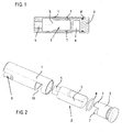
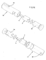
- the inventive device for damping a toilet seat or a toilet lid has according to FIG. 1 a first sleeve 1, a damper 2 received in the sleeve and a first end piece 3.
- the damper comprises a pin portion 4 and a cylinder portion 5 which is flattened at its end opposite the pin portion.
- the end piece 3 has a bore 6 into which a toilet bowl assigned (not shown) mounting pin can be inserted for attaching the device to a toilet bowl.
- a toilet bowl assigned (not shown) mounting pin can be inserted for attaching the device to a toilet bowl.
- the damper 3 At its side facing the damper 3 carries the tailpiece two web-like projections 7 which engage around the flattened portion of the cylinder 5 and thus holds the cylinder portion in the circumferential direction.
- an O-ring 8 is arranged, which fixes the end piece in the sleeve and prevents unwanted sliding out. As a rule, the O-ring 8 will be arranged in a groove 3 associated with the end piece.
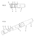
- FIG. 2 shows the damping device after FIG. 1 in a perspective exploded view.
- the damper 2 is first inserted into the sleeve 1. He arrives with its pivot 4 in engagement with a formed in the sleeve complementary receiving portion 9, which is designed as a radial slot, which creates an opening to the interior of the sleeve.
- the pin 4 is thus always connected rotationally fixed to the sleeve 1.
- the end piece 3 is inserted together with the O-ring 8 in the sleeve 1, in such a way that the two web-like projections 7 engage around the flattened portion of the cylinder 5.
- an insertion of the end piece 3 together with already pre-assembled damper 2 in the sleeve 1 is possible. In any case, the assembly of the device according to the invention is very easy.
- FIGS. 3 and 4 show a second embodiment of the damping device according to the invention.
- the second embodiment has an end piece 11, the two webs 12 now comprise the pin 4 of the damper 2.
- the damper 2 is accommodated in a sleeve 13 which has a recess 14 in its end region, through which, when the damper 2 is plugged in, the flattened portion of the damper is non-rotatably connected to the sleeve 13.
- the cylinder portion 5 of the damper 2 rotates while the pin 4 is held by the end piece 11.
- FIG. 5 shows the first embodiment as a left-side damping device and the second embodiment as a right-side damping device.
- the tail with the cylinder portion 5 is engaged, while in the right-hand version of the pin 4 is encompassed by the webs 12 of the tail.
- Only schematically indicated are two integrally formed with a (not shown) toilet seat receptacles 14, 15 and two (also not shown) toilet cover associated receptacles 16, 17. Both the seat and the lid are in the closed position.
- the receptacle 17 assigned to the cover is in engagement with the sleeve 1.
- the sleeve 1 (and with the sleeve 1 also the pin 4) rotates.
- the cylinder section 5 the damper 2 remains stationary.
- the seat associated with the receptacle 15 slides in a pivoting of the seat on the sleeve 1 from.
- the receptacle 14 assigned to the seat is non-rotatably connected to the sleeve 13. If the seat is pivoted, the sleeve 13 rotates and takes the cylinder portion 5 of the damper, while the pin is held by the end piece 11.
- the lid receptacle 16 slides on pivoting of the lid on the sleeve 13 (the lid is, however, as described in the section previously damped on the left-side arrangement).
- a great advantage of the invention is that the damper used 2 - and in particular their pin 4 - are charged only in the direction of rotation.
- the z. T. considerable lateral forces are absorbed by the sleeve 1, 13 and passed over the end piece 3, 11 in the toilet bowl or ceramic.
- the life of the damper is significantly increased over comparable conventional designs.
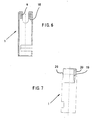
- FIGS. 6 and 7 show the sleeve 1 of the first embodiment in isolation.
- the damper rests against a stop 18 (see FIG FIG. 6 ), wherein the pin of the damper engages in the formed as a radial slot receiving portion 9 of the sleeve 1, which creates a breakthrough to the interior of the sleeve.
- the sleeve 1 has on its outer side a groove 19 which allows an accurate positioning of the sleeve - and thus of the damper.
- the groove 19 engages an associated in one of the receptacles 15 or 17 trained web. It can also be provided several grooves / webs. Although the grooves / webs with suitable training for transfer provide the torque required positive rotational engagement, but their task is primarily in the positioning of the sleeve.
- the actual engagement for power transmission creates a flattening 20, which is formed by the formed as a radial slot receiving portion 9. In the flat 20 engages a (not shown) the toilet seat or toilet cover associated web.
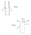
- FIGS. 8 and 9 show the sleeve of the second embodiment in isolation.
- the damper (not shown) is located on a stop 21 (see FIG. 8 ), wherein the flattened portion of the cylinder portion of the damper engages in the formed as a radial slot receiving portion of the sleeve 13, which creates an opening to the interior of the sleeve.
- On the outside of the sleeve one or more grooves 22 are formed, engage in the associated formed in one of the receptacles 14 or 16 webs. If the grooves 19 and 21 are distributed differently over the outer circumference of the sleeve, a safeguard against insertion of the sleeve in the wrong side can be avoided.
- a different cross-sectional shape or width of the groove and webs can have the same effect.
- the actual power transmission takes place via a flattening 23 and optionally via an opposite flattening 24 into which a web 25 of the toilet seat (see the right-side damper arrangement in FIG. 5 ) or a web of the toilet lid engages.
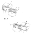
- FIG. 10 shows a further pair of damping devices according to the invention in an exploded perspective view, which is adapted to another form of damper 2.
- the left-side damping device arranged in the figure above and the right-side damping device have identical end pieces 26.
- the two sleeves 27 and 28 are also formed with sleeve ends open on both sides, wherein the sleeve 27 receives the pin 4 opposite portion of the damper, while the sleeve 28 defines the pin 4.
- grooves 29 are formed, which with webs 30 (see FIG. 11 ) are engaged. It is steamed the toilet lid. The recording associated with the toilet ring slides on a pivoting movement on the sleeve.
- FIG. 11 shows both damping devices mounted.
- FIG. 12 Referring to the in a sectional view of an embodiment similar to that of FIG. 1 is shown. Between an end piece 32 and a sleeve 33 of the damper 2 is received, wherein two webs 341 engage around the flattened portion of the cylinder 5. The sleeve 33 is engaged with the pin 4 of the damper 2 and thus creates a rotationally fixed connection. In the outer wall of the sleeve 33, a groove 34 is formed, in which a (not shown) retaining ring is inserted, which is a sliding out of the unit 33, damper 2 and end piece 32 from the receptacle of the (not shown) toilet seat or Toilet lids prevented. The retaining ring is placed in a recess in the toilet seat or in the toilet lid, preferably in the region of the joint.
- FIGS. 13 to 15 is for fixing the tail on a mounting pin a screw 35 is provided, which is screwed radially into the end piece. From the FIGS. 14 and 15 It is clear that the screw is accessible even when the end piece, via a slot 36 which limits the rotational movement of the sleeve 33 when the fastening pin is inserted.
- the screw 35 is screwed so far into the tailpiece for attachment to the mounting pin that the sleeve can slide freely on the tail.
- FIGS. 16 to 19 show a the embodiment according to FIGS. 12 to 15 configured embodiment, but in the present case a right-side damping device.
- the device according to the invention can be completely integrated in the receptacle.
- the arrangement can be made so that only the end of the tail is visible.
- the end piece may be directly formed with a pin and e.g. be connected via a bayonet-type closure with the sleeve.
- the mounting hole shown corresponds to the rule.
- the device according to the invention can be used both as a right-side and as a left-side damping device and is not limited to the illustrated shape of the receptacles of the seat and lid.
Landscapes
- Health & Medical Sciences (AREA)
- Public Health (AREA)
- Toilet Supplies (AREA)
- Fluid-Damping Devices (AREA)
Abstract
Description
Die Erfindung betrifft eine Einrichtung zum Dämpfen eines WC-Sitzes oder eines WC-Deckels.The invention relates to a device for damping a toilet seat or a toilet lid.
Derartige Einrichtungen sind seit längerem bekannt. Sie verhindern, dass ein WC-Sitz oder -Deckel beim Schließen lautstark aufsetzt. Bei vielen Konstruktionen ist lediglich ein kurzes Einleiten des Schließvorgangs erforderlich, und der WC-Sitz oder -Deckel senkt sich anschließend den restlichen Weg langsam ab, bis er sanft aufsetzt.Such devices have been known for some time. They prevent a toilet seat or lid from clanging loudly when closing. In many constructions, only a brief initiation of the closing operation is required, and the toilet seat or lid then slowly lowers the rest of the way until it gently touches down.
Der Stand der Technik bietet ein Vielfalt von Dämpfungseinrichtungen. Die
Heute werden Rotationsdämpfer bereits in sehr kleinen Größen angeboten. Der Durchmesser handelsüblicher Dämpfer kann beispielsweise nur 1 cm betragen. Dennoch bieten sie ausreichende Dämpfung und Stabilität. Die Dämpfer werden in der Sanitärtechnik bei der Herstellung von WC-Sitz-Deckel-Kombinationen als Zukaufteile eingesetzt.Today, rotary dampers are already available in very small sizes. The diameter of commercially available dampers can be for example only 1 cm. Nevertheless, they offer sufficient cushioning and stability. The dampers are in the sanitary technology used in the production of toilet seat cover combinations as purchased parts.
Die WC-Sitz-Deckel-Kombination gemäß der
Die bekannte Anordnung baut sehr kompakt. Der WC-Sitz und der WC-Deckel sind direkt auf dem Dämpfer und dem Adapter gelagert. Der Dämpfer und insbesondere der Drehzapfen des Dämpfers werden jedoch vor allem bei einer Betätigung des WC-Deckels stark belastet, da der WC-Deckel ausschließlich von dem Zapfen getragen wird. Dies kann zu einer Beschädigung des Dämpfers, zum Austritt der Dämpfungsflüssigkeit oder gar zu einem Abbrechen des Zapfens und damit vollständiger Zerstörung des Dämpfers führen. Die Gefahr ist dann besonders groß, wenn beim Schließen zusätzlich zu dem Eigengewicht des WC-Deckels (oder WC-Sitzes) eine Schließkraft, beispielsweise durch Herunterdrücken, hinzukommt.The known arrangement is very compact. The toilet seat and the toilet lid are mounted directly on the damper and the adapter. However, the damper and in particular the pivot of the damper are heavily loaded, especially when an actuation of the toilet lid, since the toilet lid is supported solely by the pin. This can lead to damage to the damper, to the escape of the damping fluid or even to a break of the pin and thus complete destruction of the damper. The danger is particularly great when closing in addition to the weight of the toilet lid (or toilet seat) a closing force, for example, by pressing down, added.
Der Erfindung liegt die Aufgabe zugrunde, eine Dämpfungsanordnung zu schaffen, die kompakt ist und darüber hinaus eine verbesserte Standzeit aufweist.The invention has for its object to provide a damping arrangement which is compact and moreover has an improved service life.
Erfindungsgemäß wird diese Aufgabe gelöst durch eine Einrichtung zum Dämpfen eines WC-Sitzes oder eines WC-Deckels, mit
- einem Dämpfer, der ein erstes und ein relativ zu dem ersten Ende drehbares zweites Ende aufweist,
- einer Hülse zur Aufnahme des Dämpfers, wobei der Dämpfer mit seinem ersten oder seinem zweiten Ende drehfest in Eingriff mit der Hülse steht,
- einem Endstück, das drehbar mit der Hülse verbunden ist und drehfest mit dem anderen Ende des Dämpfers in Eingriff steht,
- wobei das Endstück mit einem dem WC-Sitz und/oder dem WC-Deckel zugeordneten WC-Becken verbindbar ist und
- wobei der WC-Sitz oder der WC-Deckel drehfest mit der Hülse verbindbar ist.
- a damper having first and second ends rotatable relative to the first end,
- a sleeve for receiving the damper, wherein the damper with its first or its second end is rotationally fixed in engagement with the sleeve,
- an end piece which is rotatably connected to the sleeve and rotatably engaged with the other end of the damper,
- wherein the tail with a toilet seat and / or the toilet lid associated toilet bowl is connected and
- wherein the toilet seat or the toilet lid is rotatably connected to the sleeve.
Die Erfindung vereint gegenüber herkömmlichen Dämpferanordnungen mehrere Vorteile. Ein wesentlicher Vorteil besteht in der Stabilität der Konstruktion bei gleichzeitig minimalem Platzbedarf. Geschaffen wird dieser Vorteil durch die den Dämpfer zumindest teilweise umgebende Hülse. Beim Schließvorgang auftretende Querkräfte wirken nicht - wie bei herkömmlichen Lösungen - unmittelbar auf den empfindlichen Zapfen des Dämpfers, sondern werden in die Hülse geleitet, und von dort über das Endstück (und in aller Regel einen Befestigungszapfen) in das WC-Becken. Der Dämpfer selbst bleibt in der Richtung quer zur Drehachse weitestgehend unbelastet. Ein hohe Lebensdauer ist die Folge.
Ein weiterer Vorteil der Erfindung liegt in der einfachen Handhabung, und zwar insbesondere dann, wenn der Dämpfer, die Hülse und das Endstück zu einer Einheit zusammenfügbar und die Einheit in eine Aufnahme in einem WC-Sitz und/oder einem WC-Deckel einsteckbar ist, wie es zweckmäßigerweise vorgesehen ist. Die Kombination aus Dämpfer, Hülse und Endstück kann dem Endverbraucher vormontiert zur Verfügung gestellt werden. Ein Zusammenstecken einzelner Bauelemente vor Ort kann entfallen.The invention combines several advantages over conventional damper arrangements. A major advantage is the stability of the construction with minimal space requirements. This advantage is created by the damper at least partially surrounding sleeve. Occurring during closing transverse forces do not act - as in conventional solutions - directly on the sensitive pin of the damper, but are directed into the sleeve, and from there via the tail (and usually a mounting pin) in the toilet bowl. The damper itself remains largely unloaded in the direction transverse to the axis of rotation. A long life is the result.
A further advantage of the invention lies in the ease of handling, in particular when the damper, the sleeve and the end piece can be joined together in one unit and the unit can be inserted into a receptacle in a toilet seat and / or a toilet lid, as appropriate. The combination of damper, sleeve and End piece can be made available to the end user pre-assembled. A mating of individual components on site can be omitted.
Die Hülse ist vorzugsweise aus Metall, beispielsweise aus Edelstahl, oder aus Hartkunststoff hergestellt.The sleeve is preferably made of metal, for example stainless steel, or made of hard plastic.
Vorteilhafterweise weist die Hülse in ihrem Außerumfang eine Nut auf, in die im eingebauten Zustand ein Sicherungsring eingreift, der zur Sicherung der Hülse in einer Aufnahme des WC-Sitzes und/oder WC-Deckels dient. Damit wird die Gefahr unterbunden, dass die Hülse oder die gesamte Dämpfereinheit aus dem WC-Sitz bzw. -Deckel herausgleitet. Der Sicherungsring ist im eingebauten Zustand nicht sichtbar. Er sitzt beispielsweise in einer Aussparung im WC-Sitz oder -Deckel, vorzugsweise unmittelbar an der Stoßstelle zwischen WC-Sitz und WC-Deckel.Advantageously, the sleeve has in its outer periphery a groove into which engages a circlip in the installed state, which serves to secure the sleeve in a receptacle of the toilet seat and / or toilet lid. This prevents the risk that the sleeve or the entire damper unit slides out of the toilet seat or lid. The circlip is not visible when installed. He sits, for example, in a recess in the toilet seat or cover, preferably directly at the joint between the toilet seat and toilet lid.
In wesentlicher Weiterbildung der Erfindung wird vorgeschlagen, dass die Hülse in ihrer Umfangswandung einen Schlitz aufweist, durch den hindurch zur Befestigung des WC-Deckels oder des WC-Sitzes an das WC-Becken ein Befestigungszapfen in das Endstück greift. Der Schlitz erstreckt sich in Umfangsrichtung und verhindert bei eingestecktem Befestigungszapfen ein Herausgleiten des Endstücks aus der Hülse. Bei der Vormontage der Dämpferanordnung kann der Befestigungszapfen (ggf. einschließlich Befestigungsanordnung für das WC-Becken) mit der Dämpfungseinrichtung verbunden werden, was die spätere Endmontage vor Ort nochmals erleichtert und vor allem die Anzahl "loser" Teile reduziert.In an essential embodiment of the invention, it is proposed that the sleeve has a slot in its circumferential wall, through which a fastening pin engages in the end piece for securing the toilet lid or the toilet seat to the toilet bowl. The slot extends in the circumferential direction and prevents plug-in mounting pin slipping out of the tail of the sleeve. In the pre-assembly of the damper assembly of the mounting pin (possibly including mounting arrangement for the toilet bowl) can be connected to the damping device, which facilitates the subsequent final assembly on site again and especially reduces the number of "loose" parts.
Der Endbereich der erfindungsgemäßen Einrichtung liegt in vollständig montiertem Zustand frei und ist demgemäß in bestimmten Stellungen des WC-Sitzes oder -Deckels sichtbar. Vorzugsweise ist daher das Endstück in die Hülse eingesteckt. Dies schafft eine besonders kompakte und ästhetisch ansprechende Bauform, und zwar insbesondere dann, wenn der Außendurchmesser des Endes des Endstücks an den Außendurchmesser der Hülse angepasst ist. Es sei jedoch darauf hingewiesen, dass auch Bauformen denkbar sind, bei denen das Endstück die Hülse übergreift. Das Endstück wird dann mindestens in einem Abschnitt hülsenartig ausgebildet sein. In beiden Fällen kann ein durch den Schlitz hindurchgesteckter Zapfen das Endstück in der Hülse fixieren.The end region of the device according to the invention is free in the fully assembled state and is accordingly visible in certain positions of the toilet seat or cover. Preferably, therefore, the tail is inserted into the sleeve. This provides a particularly compact and aesthetically pleasing design, especially when the outer diameter of the end of the tail is adapted to the outer diameter of the sleeve. It should be noted, however, that designs are conceivable in which the end piece engages over the sleeve. The tail will then be sleeve-like at least in one section. In both cases, a pin inserted through the slot can fix the end piece in the sleeve.
Übliche Dämpfer zum Dämpfen einer Drehbewegung weisen in der Regel mindestens einen mit dem Drehzapfen verbundenen Flügel auf, der beim Drehen des Drehzapfens eine viskose Flüssigkeit von einer Kammer in eine andere Kammer drängt. Konstruktionsbedingt ist der Winkel, innerhalb dessen der Drehzapfen bewegbar ist, begrenzt. Bei Verwendung von zwei diametral gegenüberliegenden Flügeln ist der Winkelbereich beispielsweise auf 110° festgelegt. Wird der festgelegte Arbeitsbereich überschritten, kann der Dämpfer zerstört werden. Bei WC's ist die Gefahr besonders groß, da die Anschläge in der Öffnungsstellung von Deckel und Sitz von WC-Einbau zu WC-Einbau variieren kann und die Hebelwirkung gerade bei einem WC-Sitz oder -Deckel erheblich ist. Vorzugsweise begrenzt daher der Schlitz die Öffnungsund/oder die Schließbewegung des WC-Deckels oder des WC-Sitzes. Damit wird die Gefahr ausgeschlossen, dass der Dämpfer "überdreht" und zerstört wird. Der Schlitz schafft einen Anschlag, der die Bewegung des WC-Sitzes oder des WC-Deckels vor Erreichen der kritischen Winkelstellung des Dämpfers stoppt.Conventional dampers for damping rotary motion typically have at least one wing connected to the pivot which, upon rotation of the pivot, urges viscous fluid from one chamber to another chamber. By design, the angle within which the pivot is movable limited. When using two diametrically opposed wings, the angular range is set, for example, to 110 °. If the specified working range is exceeded, the damper can be destroyed. In WC's, the danger is particularly great, since the attacks in the open position of the lid and seat of toilet installation can vary to toilet installation and the leverage is significant, especially in a toilet seat or cover. Preferably, therefore, the slot limits the opening and / or the closing movement of the toilet lid or the toilet seat. This eliminates the risk that the damper will be "over-tightened" and destroyed. The slot provides a stop that stops the movement of the toilet seat or the toilet lid before reaching the critical angular position of the damper.
Grundsätzlich kann es von Vorteil sein, das Endstück zusätzlich an dem Befestigungszapfen zu sichern. Ein konstruktiv günstige Lösung zeichnet sich dadurch aus, dass zur Festlegung an dem Befestigungszapfen im Endstück eine Schraube angeordnet ist, die durch den Schlitz hindurch erreichbar ist. Bei der Schraube kann es sich um eine Madenschraube handeln. In einer Endstellung des WC-Sitzes bzw. -Deckels ist die Schraube von der Außenwandung der Hülse verdeckt. In der anderen Endstellung - vorzugsweise der geöffneten Stellung - ist die Schraube zugänglich.In principle, it may be advantageous to additionally secure the end piece to the fastening pin. A structurally favorable solution is characterized in that for fixing to the mounting pin in the tail a screw is arranged, which can be reached through the slot. The screw can be a grub screw. In an end position of the toilet seat or cover, the screw is covered by the outer wall of the sleeve. In the other end position - preferably the open position - the screw is accessible.
Die Hülse weist auf ihrem Außenumfang zweckmäßigerweise mindestens einen profilierten Bereich auf, der mit einem zugehörigen Bereich des WC-Sitzes oder WC-Deckels in formschlüssigem Eingriff steht. Eine in Hinblick auf eine gute Handhabbarkeit günstige Weiterbildung der Erfindung ist dadurch gekennzeichnet, dass der profilierte Bereich mindestens eine Nut oder einen Steg umfasst oder als Abflachung ausgebildet ist und dass der zugehörige Bereich des WC-Sitzes oder WC-Deckels als Steg oder Nut oder als Erhebung ausgebildet ist. Ist die Dämpfungsanordnung noch nicht vormontiert, wird zur Montage der Gesamteinrichtung beispielsweise zunächst der Dämpfer und die Hülse eingesteckt und die Hülse durch das Endstück "verschlossen". Die Hülse wird anschließend mitsamt dem Dämpfer und dem Endstück als kompakte Einheit in eine integral mit dem WC-Sitz oder -Deckel ausgebildete Aufnahme eingeführt, wobei die Nuten und Stege für eine korrekte Positionierung der Einheit in Umfangsrichtung sorgen. Ferner kann durch die Nute/Stege eine einfache drehfeste Verbindung geschaffen werden. Sowohl das Endstück als auch der Dämpfer sind einfach und ohne die Gefahr einer Fehlstellung montierbar. Gleiches gilt selbstverständlich, wenn zuerst die Hülse und nachfolgend der Dämpfer eingesteckt wird. Alternativ zu der Montage vor Ort gestattet die erfindungsgemäße Anordnung wie zuvor beschrieben eine Vormontage, wobei später zur Endmontage lediglich die Gesamtanordnung in die Aufnahme(n) eingesteckt werden brauchen.The sleeve expediently has on its outer circumference at least one profiled region which is in positive engagement with an associated region of the toilet seat or toilet lid. A development of the invention which is favorable in terms of good handleability is characterized in that the profiled area comprises at least one groove or a web or is formed as a flattening and that the associated area of the toilet seat or toilet lid acts as a web or groove or as Survey is formed. If the damping arrangement is not preassembled, for example, the damper and the sleeve is first inserted for mounting the entire device and the sleeve is "closed" by the end piece. The sleeve is then inserted together with the damper and the end piece as a compact unit in a integrally formed with the toilet seat or cover receptacle, wherein the grooves and webs ensure correct positioning of the unit in the circumferential direction. Furthermore, by the groove / webs a simple rotationally fixed connection can be created. Both the tail and the damper are easy and without the risk of misalignment mountable. The same applies, of course, when first the sleeve and then the damper is inserted. As an alternative to on-site assembly, the arrangement according to the invention allows a pre-assembly as described above, with only the entire assembly needing to be inserted into the receptacle (s) later for final assembly.
Zwischen dem Endstück und der Innenwandung der Hülse kann ein O-Ring vorgesehen sein. Der O-Ring verhindert, dass sich ein bereits eingesetztes Endstück ungewollt wieder aus der Hülse löst. Gleichwohl bietet er nur so großen Widerstand, dass das Endstück zur Auswechslung des Dämpfers problemlos abgenommen werden kann.Between the tail and the inner wall of the sleeve, an O-ring may be provided. The O-ring prevents an already inserted end unintentionally released from the sleeve. Nevertheless, it offers only so much resistance that the tail can be easily removed to replace the damper.
Die Erfindung kann zur Dämpfung beispielsweise nur eines Deckels eingesetzt werden. Wie bereits zuvor angedeutet, liegt ein häufiges Anwendungsgebiet jedoch in der gleichzeitigen Dämpfung von WC-Sitz und WC-Deckel. Hierzu sind ein rechtsseitiger und ein linksseitiger Dämpfer erforderlich. Zur Erhöhung der Sicherheit bei der Montage der erfindungsgemäßen Einrichtung ist vorgesehen, dass die Nut oder der Steg der einen Hülse versetzt zu der Nut oder dem Steg der anderen Hülse liegen. Es kann jeweils ein unterschiedlicher Winkelabstand gewählt werden. So ist eindeutig festgelegt, welche Dämpfungseinrichtung welcher Seite zuzuordnen ist. Im übrigen ist auch eine unterschiedliche Querschnittsgestaltung oder Breite der Nute/Stege denkbar, um die Zuordnung eindeutig festzulegen.The invention can be used for damping, for example, only a lid. As previously indicated, however, a common field of application is the simultaneous damping of toilet seat and toilet lid. For this purpose, a right-side and a left-side damper are required. To increase the safety during assembly of the device according to the invention it is provided that the groove or the web of a sleeve offset from the groove or the web of the other sleeve. It can be selected in each case a different angular distance. Thus, it is clearly defined which damping device is to be assigned to which side. Incidentally, a different cross-sectional configuration or width of the groove / webs is conceivable to uniquely determine the assignment.
Bei der Montage der Dämpfungseinrichtung in der Aufnahmelasche des WC-Sitzes oder WC-Deckels spielt die richtige Positionierung der Dämpfungseinrichtung in Umfangsrichtung eine wichtige Rolle. Es wird für eine eindeutige Festlegung der Position vorgeschlagen, dass der Außenumfang der Hülse mit mindestens zwei Nute oder Stege belegt ist, die den Außenumfang in unterschiedlich große Winkelbereiche aufteilen. Sind im Außenumfang beispielsweise zwei Nute ausgebildet, so sollen die Winkelbereiche nicht gleich groß, also (idealisiert) 180°, sein, da sonst zwei Orientierungsmöglichkeiten der Dämpfungseinrichtung gegeben wären.When mounting the damping device in the receiving lug of the toilet seat or toilet lid, the correct positioning of the damping device in the circumferential direction plays an important role. It is suggested for a clear definition of the position that the Outer circumference of the sleeve is covered with at least two grooves or webs, which divide the outer periphery in different sized angle ranges. If, for example, two grooves are formed in the outer circumference, then the angular ranges should not be the same size, ie (idealized) 180 °, since otherwise two orientation possibilities of the damping device would be present.
Aus Stabilitätsgründen kann es vorteilhaft sein, wenn das Endstück bis in einen Hülsenaufnahmebereich des WC-Sitzes oder des WC-Deckels hineinragt. Der Hülsenaufnahmebereich kann wie zuvor beschrieben integral am rückwärtigen Ende des WC-Sitzes oder -Deckels angeformt sein. Das Endstück braucht nur einen kleinen Abschnitt aus der Lasche herauszustehen. Ebenfalls eine stabile Anordnung wird durch einen möglichst großen Angriffsbereich zwischen dem Endstück und der Hülse geschaffen. Die bei Belastung zum Teil erheblichen Querkräfte können somit gut aufgenommen werden.For stability reasons, it may be advantageous if the tail protrudes into a sleeve receiving area of the toilet seat or the toilet lid. The sleeve receiving portion may be integrally formed at the rear end of the toilet seat or lid as described above. The tail needs to stand out only a small portion of the tab. Also, a stable arrangement is created by the largest possible attack area between the tail and the sleeve. The sometimes considerable lateral forces under load can thus be well absorbed.
Die Hülse kann grundsätzlich vielfältig ausgebildet sein. Sie muss auf ihrer einen Seite das Endstück (drehbar) aufnehmen und auf ihrer anderen Seite den Zapfen des Dämpfers oder sein entgegengesetztes Ende arretieren. Eine besonders einfache Gestaltung der Hülse zeichnet sich dadurch aus, dass ein Ende der Hülse stirnseitig eine Aussparung aufweist, die einen Durchbruch zum Inneren der Hülse schafft und zur Aufnahme eines Endes des Dämpfers dient. Handelsübliche Dämpfer weisen häufig abgeflachte Enden auf, so dass man für die Aussparung beispielsweise eine senkrecht zur Dämpferachse verlaufende Ausnehmung wählen wird, die von außen besonders leicht herzustellen ist.The sleeve can in principle be varied. It has to take up the end piece (turnable) on one side and lock on its other side the pin of the damper or its opposite end. A particularly simple design of the sleeve is characterized in that one end of the sleeve has a frontal end a recess which provides an opening to the interior of the sleeve and serves to receive one end of the damper. Commercially available dampers often have flattened ends, so that one will choose, for example, a recess running perpendicular to the damper axis, which is particularly easy to produce from the outside.
Im folgenden wird die Erfindung anhand eines bevorzugten Ausführungsbeispiels unter Bezugnahme auf die beigefügte Zeichnung näher erläutert. Die Zeichnung zeigt in:
-
Figur 1 -
Figur 2Figur 1 ; -
Figur 3 -
Figur 4Figur 3 ; -
Figur 5 -
Figur 6 -
Figur 7Figur 6 ; -
Figur 8 -
Figur 9Figur 8 ; -
Figur 10 -
Figur 11Figur 10 in eingebautem Zustand; -
Figur 12 -
Figur 13Ausführungsbeispiel gemäß Figur 12 in einer perspektivischen auseinandergezogenen Ansicht; -
Figur 14Ausführungsbeispiel gemäß Figur 12 in zusammengesetztem Zustand; -
Figur 15Figur 12 -
Figur 16 -
Figur 17Ausführungsbeispiel gemäß Figur 16 in einer perspektivischen auseinandergezogenen Ansicht; -
Figur 18Ausführungsbeispiel gemäß Figur 16 in zusammengesetztem Zustand; -
Figur 19Figur 16
-
FIG. 1 a schematic representation of a partial cross-sectional view of a first embodiment according to the invention of a damping device, in this case a left-side damping device; -
FIG. 2 in a schematic representation of a perspective exploded view of the embodiment according toFIG. 1 ; -
FIG. 3 a schematic representation of a partial cross-sectional view of a second embodiment according to the invention of a damping device, in this case a right-side damping device; -
FIG. 4 in a schematic representation of a perspective exploded view of the embodiment according toFIG. 3 ; -
FIG. 5 in a schematic representation of a partially sectioned perspective view of the first and second embodiments according to the invention in the installed state; -
FIG. 6 a cross-sectional view of a first sleeve in isolation; -
FIG. 7 a side view of the sleeve afterFIG. 6 ; -
FIG. 8 a cross-sectional view of a second sleeve in isolation; -
FIG. 9 a side view of the sleeve afterFIG. 8 ; -
FIG. 10 a schematic representation of a perspective view of another right and left side embodiment; and -
FIG. 11 the left and the right side embodiment afterFIG. 10 in installed condition; -
FIG. 12 a schematic representation of a partial cross-sectional view of another embodiment, in this case a left-side damping device; -
FIG. 13 the embodiment according toFIG. 12 in a perspective exploded view; -
FIG. 14 the embodiment according toFIG. 12 in assembled condition; -
FIG. 15 a cross-sectional view according to line XV-XV inFIG. 12 ; -
FIG. 16 a schematic representation of a partial cross-sectional view of another embodiment, in this case a right-side damping device; -
FIG. 17 the embodiment according toFIG. 16 in a perspective exploded view; -
FIG. 18 the embodiment according toFIG. 16 in assembled condition; -
FIG. 19 a cross-sectional view according to line XIX-XIX inFIG. 16 ;
Die erfindungsgemäße Einrichtung zum Dämpfen eines WC-Sitzes oder eines WC-Deckels weist gemäß
Das Endstück 3 weist eine Bohrung 6 auf, in die zur Befestigung der Einrichtung an einer WC-Schüssel ein dem WC-Becken zugeordneter (nicht gezeigter) Befestigungszapfen einsteckbar ist. An seiner dem Dämpfer 3 zugewandten Seite trägt das Endstück zwei stegartige Ansätze 7, die den abgeflachten Abschnitt des Zylinders 5 umgreifen und den Zylinderabschnitt somit in Umfangsrichtung hält. Zwischen der Hülse 1 und dem Endstück 3 ist ein O-Ring 8 angeordnet, der das Endstück in der Hülse fixiert und ein ungewolltes Herausgleiten verhindert. In aller Regel wird man den O-Ring 8 in einer dem Endstück 3 zugeordneten Nut anordnen.The
Zum besseren Verständnis der Funktionsweise der Dämpfungseinrichtung sei bereits an dieser Stelle darauf hingewiesen, dass im eingebauten Zustand ein WC-Sitz oder ein WC-Deckel in Eingriff mit der Hülse 1 steht. Wird der (hier nicht gezeigte) WC-Deckel oder -Sitz geschwenkt, dreht sich die Hülse 1 - und damit auch der Drehzapfen 4 - während das mit einer Keramik verbundene Endstück 3 feststeht und den Zylinderabschnitt 5 des Dämpfers 2 in Position hält. Die Schwenkbewegung des Sitzes oder Deckels wird durch einen in der Hülse ausgebildeten Schlitz 10 in der Umfangswandung der Hülse 1 begrenzt, wie es im folgenden noch näher erläutert wird.For a better understanding of the operation of the damping device should already be noted at this point that when installed a toilet seat or a toilet cover is in engagement with the
Bei der linksseitigen Anordnung steht die dem Deckel zugeordnete Aufnahme 17 in Eingriff mit der Hülse 1. Wird also der Deckel geschwenkt, dreht sich die Hülse 1 (und mit der Hülse 1 auch der Zapfen 4) mit. Der Zylinderabschnitt 5 des Dämpfers 2 bleibt ortsfest. Die dem Sitz zugeordnete Aufnahme 15 gleitet bei einem Schwenken des Sitzes auf der Hülse 1 ab.In the case of the left-side arrangement, the
Bei der rechtsseitigen Anordnung ist die dem Sitz zugeordnete Aufnahme 14 drehfest mit der Hülse 13 verbunden. Wird der Sitz geschwenkt, dreht sich die Hülse 13 und nimmt den Zylinderabschnitt 5 des Dämpfers mit, während der Zapfen durch das Endstück 11 gehalten wird. Die Deckel-Aufnahme 16 gleitet beim Schwenken des Deckels auf der Hülse 13 ab (der Deckel wird jedoch, wie im Abschnitt zuvor beschrieben, über die linksseitige Anordnung gedämpft).In the right-hand arrangement, the
Ein großer Vorteil der Erfindung besteht darin, dass die eingesetzten Dämpfer 2 - und insbesondere deren Zapfen 4 - nur in Drehrichtung belastet werden. Die z. T. erheblichen Querkräfte werden von der Hülse 1, 13 aufgenommen und über das Endstück 3, 11 in die WC-Schüssel oder Keramik geleitet. Die Lebensdauer der Dämpfer ist gegenüber vergleichbaren herkömmlichen Konstruktionen deutlich erhöht.A great advantage of the invention is that the damper used 2 - and in particular their pin 4 - are charged only in the direction of rotation. The z. T. considerable lateral forces are absorbed by the
Die
Die Hülse 1 weist auf ihrer Außenseite eine Nut 19 auf, die eine genaue Positionierung der Hülse - und damit des Dämpfers - gestattet. In die Nut 19 greift ein zugehöriger in einer der Aufnahmen 15 oder 17 ausgebildeter Steg ein. Es können auch mehrere Nute/Stege vorgesehen sein. Zwar können die Nute/Stege bei geeigneter Ausbildung den zur Übertragung des Drehmoments erforderlichen formschlüssigen Dreh-Eingriff zur Verfügung stellen, jedoch liegt ihre Aufgabe in erster Linie in der Positionierung der Hülse. Den eigentlichen Eingriff zur Kraftübertragung schafft eine Abflachung 20, die durch den als radialer Schlitz ausgebildeten Aufnahmeabschnitt 9 gebildet ist. In die Abflachung 20 greift ein (nicht gezeigter) dem WC-Sitz oder WC-Deckel zugeordneter Steg ein.The
Die
Die in der Figur oben angeordnete linksseitige Dämpfungseinrichtung und die rechtsseitige Dämpfungseinrichtung weisen identische Endstücke 26 auf. Die beiden Hülsen 27 und 28 sind ebenfalls mit beidseitig offenen Hülsenenden ausgebildet, wobei die Hülse 27 den dem Zapfen 4 gegenüberliegenden Abschnitt des Dämpfers aufnimmt, während die Hülse 28 den Zapfen 4 festlegt. In der Außenwandung der Hülse 27 sind Nute 29 ausgebildet, die mit Stegen 30 (siehe
Umgekehrt wird bei der oberen Anordnung der WC-Sitz gedämpft. Hier stehen Nute 29 mit dem WC-Sitz zugeordneten Stegen 31 (siehe
Es wird auf
Wie es am besten aus den
Die
Im Rahmen der Erfindung sind durchaus Abwandlungen möglich. Beispielsweise kann aus Stabilitätsgründen die erfindungsgemäße Einrichtung vollständig in der Aufnahme integriert sein. Die Anordnung kann so getroffen werden, dass lediglich das Ende des Endstücks sichtbar ist. Auch kann das Endstück direkt mit einem Zapfen ausgebildet sein und z.B. über einen bajonettartigen Verschluss mit der Hülse verbunden werden. Die gezeigte Aufnahmebohrung entspricht jedoch dem Regelfall. Im übrigen kann die erfindungsgemäße Einrichtung sowohl als rechts- als auch als linksseitige Dämpfungseinrichtung eingesetzt werden und ist nicht auf die dargestellte Form der Aufnahmen des Sitzes und Deckels beschränkt.In the context of the invention modifications are possible. For example, for stability reasons, the device according to the invention can be completely integrated in the receptacle. The arrangement can be made so that only the end of the tail is visible. Also, the end piece may be directly formed with a pin and e.g. be connected via a bayonet-type closure with the sleeve. However, the mounting hole shown corresponds to the rule. Moreover, the device according to the invention can be used both as a right-side and as a left-side damping device and is not limited to the illustrated shape of the receptacles of the seat and lid.
Claims (15)
- A device for damping a toilet seat or a toilet cover, including- a damper (2), which has a first end and a second end which is rotatable relative to the first end,- a sleeve (1;13;33) for receiving the damper (2), the first or second end of the damper being in rotationally fixed engagement with the sleeve, and- an end piece (3;11;32), which is rotatably connected to the sleeve (1;13;33) and is in rotationally fixed engagement with the other end of the damper (2),- wherein the end piece (3;11;32) is connectable to a toilet bowl associated with the toilet seat and/or the toilet cover and- wherein the toilet seat or the toilet cover is rotationally fixedly connectable to the sleeve (1;13;33).
- A device as claimed in claim 1, characterised in that the damper, the sleeve (1;13;33) and the end piece (3;11;32) are connectable to form a unit and the unit is insertable into a recess in a toilet seat and/or a toilet cover.
- A device as claimed in claim 1 or 2, characterised in that the sleeve (1;13;33) has a groove (34) in its outer periphery and that, in the installed state, a retaining ring engages in the groove, which serves to secure the sleeve in a recess in the toilet seat and/or toiler cover.
- A device as claimed in one of claims 1 - 3, characterised in that the sleeve (1;13;33) has a slot (10;36) in its peripheral wall, through which a fastening peg engages in the end piece (3;11;32) in order to fasten the toilet cover or the toilet seat to the toilet bowl.
- A device as claimed in claim 4, characterised in that the slot (10;36) limits the opening and/or closing movement of the toilet cover or the toilet seat.
- A device as claimed in claim 4 or 5, characterised in that the end piece (3;11;32) may be secured to the fastening peg.
- A device as claimed in claim 6, characterised in that for the purpose of securing to the fastening peg, a screw (35) is arranged in the end piece (3;11;32), which is accessible through the slot (10;36).
- A device as claimed in one of claims 1-7, characterised in that the sleeve (1;13;33) has at least one profiled region on its outer periphery, which is in positive engagement with an associated region of the toilet seat or toilet cover.
- A device as claimed in claim 8, characterised in that the profiled region includes at least one groove (19;22) or a web or is a flattened region (20;23;24) and that the associated region of the toilet seat or toilet cover is constructed in the form of a web or a groove or as a raised area (25).
- A device as claimed in claim 9, characterised in that when using a damper on the right hand side and on the left hand side, the grooves (19) or webs of the one sleeve (1) are arranged offset from the grooves (22) or webs of the other sleeve (13).
- A device as claimed in one of claims 8-10, characterised in that the sleeves have at least two grooves (19;22) or webs, which divide the outer periphery of the sleeve (1;13;33) into two different angular regions.
- A device as claimed in one of claims 1 - 11, characterised in that the end piece (3;11;32) extends into a sleeve receiving region of the toilet seat or the toilet cover.
- A device as claimed in one of claims 1-12, characterised in that one end of the sleeve (1;13;32) has a cut-out (9;14) at the end, which creates an opening to the interior of the sleeve and serves to receive one end (4) of the damper (2).
- A device as claimed in one of claims 1-13, characterised in that an O-ring (8) is provided between the end piece (3;11;32) and the inner wall of the sleeve.
- A toilet seat/cover combination with at least one dampening device as claimed in one of claims 1-14.
Applications Claiming Priority (2)
| Application Number | Priority Date | Filing Date | Title |
|---|---|---|---|
| DE10353944A DE10353944B4 (en) | 2003-11-18 | 2003-11-18 | Device for damping a toilet seat or a toilet lid |
| DE10353944 | 2003-11-18 |
Publications (3)
| Publication Number | Publication Date |
|---|---|
| EP1532913A2 EP1532913A2 (en) | 2005-05-25 |
| EP1532913A3 EP1532913A3 (en) | 2006-04-19 |
| EP1532913B1 true EP1532913B1 (en) | 2008-06-04 |
Family
ID=34428792
Family Applications (1)
| Application Number | Title | Priority Date | Filing Date |
|---|---|---|---|
| EP04027382A Not-in-force EP1532913B1 (en) | 2003-11-18 | 2004-11-18 | Device for damping toilet seats and/or toilet covers |
Country Status (3)
| Country | Link |
|---|---|
| EP (1) | EP1532913B1 (en) |
| AT (1) | ATE397407T1 (en) |
| DE (2) | DE10353944B4 (en) |
Families Citing this family (5)
| Publication number | Priority date | Publication date | Assignee | Title |
|---|---|---|---|---|
| DE102004029419B4 (en) * | 2004-06-18 | 2011-04-28 | Hamberger Industriewerke Gmbh | Toilet seat hinge and toilet seat set |
| DE112006004229B4 (en) * | 2006-08-16 | 2018-07-05 | Bestter (Xiamen) Technology Inc. | A mounting bracket for the lid and seat of a toilet bowl |
| ITMI20071193A1 (en) | 2007-06-13 | 2008-12-14 | Cavagna & Sipex Internat S R L | BRAKING DEVICE INTERPONIBLE BETWEEN MUTUALLY ROTATING ELEMENTS. |
| CA2823566A1 (en) | 2011-01-03 | 2012-07-12 | Pressalit A/S | Toilet hinge arrangement |
| DE102019105939B4 (en) * | 2018-10-08 | 2022-06-30 | Hamberger Industriewerke Gmbh | Rotary damper and toilet seat set |
Family Cites Families (5)
| Publication number | Priority date | Publication date | Assignee | Title |
|---|---|---|---|---|
| DE3437138C2 (en) * | 1984-10-10 | 1986-10-30 | Pag Presswerk Ag, 4300 Essen | Toilet cover with damping elements |
| DE10051805B4 (en) * | 2000-10-18 | 2005-04-14 | Hamberger Industriewerke Gmbh | Toilet seat hinge |
| JP2003176845A (en) * | 2001-12-12 | 2003-06-27 | Sankyo Seiki Mfg Co Ltd | Damper device |
| DE20215330U1 (en) * | 2002-04-23 | 2002-12-19 | ASEM Industrieberatung und Vermittlung GmbH, 41352 Korschenbroich | Fastening device for lowering a toilet cover with quick fastening |
| DE10324172A1 (en) * | 2002-05-27 | 2003-12-11 | Mkw Iot Metall Kunststoff Und | Joint for rotational movement of sanitary element on sanitary object has damping device with first part installed rotationally fixed in recess in fastening device and second part installed rotationally fixed in recess in mounting |
-
2003
- 2003-11-18 DE DE10353944A patent/DE10353944B4/en not_active Expired - Fee Related
-
2004
- 2004-11-18 DE DE502004007312T patent/DE502004007312D1/en active Active
- 2004-11-18 AT AT04027382T patent/ATE397407T1/en not_active IP Right Cessation
- 2004-11-18 EP EP04027382A patent/EP1532913B1/en not_active Not-in-force
Also Published As
| Publication number | Publication date |
|---|---|
| DE10353944A1 (en) | 2005-06-23 |
| DE502004007312D1 (en) | 2008-07-17 |
| DE10353944B4 (en) | 2007-08-09 |
| ATE397407T1 (en) | 2008-06-15 |
| EP1532913A3 (en) | 2006-04-19 |
| EP1532913A2 (en) | 2005-05-25 |
Similar Documents
| Publication | Publication Date | Title |
|---|---|---|
| EP1290303B1 (en) | Bar lock for a locking system | |
| EP3615749B1 (en) | Window and/or door fitting | |
| DE102011051553B4 (en) | Hardware for windows or doors | |
| DE10333925A1 (en) | Furniture hinge with automatic opening, especially for furniture doors | |
| DE102008025265A1 (en) | folding cover | |
| DE102007022269A1 (en) | stop damper | |
| EP1109983B1 (en) | Screw-on hinge with blocked position | |
| CH644666A5 (en) | HINGE. | |
| DE2916242A1 (en) | SAFETY ARRANGEMENT FOR DOORS, WINDOWS OR DGL. | |
| EP1532913B1 (en) | Device for damping toilet seats and/or toilet covers | |
| EP2873787A2 (en) | Actuation handle | |
| EP1659250B1 (en) | Window, door or the like with a corner transmission | |
| DE102007003789A1 (en) | fuse element | |
| DE19932443C2 (en) | hinge | |
| EP1967111A2 (en) | Dampening device | |
| EP3363969B1 (en) | Actuation handle | |
| EP0036141B1 (en) | Lock device for casement fastener, bar shutters and the like | |
| EP0861953B1 (en) | Operating handle | |
| DE102007010930B4 (en) | attenuator | |
| DE202007003368U1 (en) | Damping device for seat or cover of WCs, has damper which comprises first section and second section rotating with reference to first section whereby damper is received in housing | |
| EP1736624A2 (en) | Transmission for an anti panic handle or bar | |
| DE10049328B4 (en) | Actuator attachment for a valve and associated kit | |
| DE102004041723B3 (en) | hinge switch | |
| DE19601119C2 (en) | Rotary actuator with cover sleeve | |
| DE9314325U1 (en) | Wing hinge |
Legal Events
| Date | Code | Title | Description |
|---|---|---|---|
| PUAI | Public reference made under article 153(3) epc to a published international application that has entered the european phase |
Free format text: ORIGINAL CODE: 0009012 |
|
| AK | Designated contracting states |
Kind code of ref document: A2 Designated state(s): AT BE BG CH CY CZ DE DK EE ES FI FR GB GR HU IE IS IT LI LU MC NL PL PT RO SE SI SK TR |
|
| AX | Request for extension of the european patent |
Extension state: AL HR LT LV MK YU |
|
| PUAL | Search report despatched |
Free format text: ORIGINAL CODE: 0009013 |
|
| AK | Designated contracting states |
Kind code of ref document: A3 Designated state(s): AT BE BG CH CY CZ DE DK EE ES FI FR GB GR HU IE IS IT LI LU MC NL PL PT RO SE SI SK TR |
|
| AX | Request for extension of the european patent |
Extension state: AL HR LT LV MK YU |
|
| 17P | Request for examination filed |
Effective date: 20060904 |
|
| AKX | Designation fees paid |
Designated state(s): AT BE BG CH CY CZ DE DK EE ES FI FR GB GR HU IE IS IT LI LU MC NL PL PT RO SE SI SK TR |
|
| GRAP | Despatch of communication of intention to grant a patent |
Free format text: ORIGINAL CODE: EPIDOSNIGR1 |
|
| GRAS | Grant fee paid |
Free format text: ORIGINAL CODE: EPIDOSNIGR3 |
|
| RAP1 | Party data changed (applicant data changed or rights of an application transferred) |
Owner name: PAGETTE GMBH |
|
| GRAA | (expected) grant |
Free format text: ORIGINAL CODE: 0009210 |
|
| AK | Designated contracting states |
Kind code of ref document: B1 Designated state(s): AT BE BG CH CY CZ DE DK EE ES FI FR GB GR HU IE IS IT LI LU MC NL PL PT RO SE SI SK TR |
|
| REG | Reference to a national code |
Ref country code: GB Ref legal event code: FG4D Free format text: NOT ENGLISH |
|
| REG | Reference to a national code |
Ref country code: CH Ref legal event code: EP |
|
| REF | Corresponds to: |
Ref document number: 502004007312 Country of ref document: DE Date of ref document: 20080717 Kind code of ref document: P |
|
| REG | Reference to a national code |
Ref country code: IE Ref legal event code: FG4D Free format text: LANGUAGE OF EP DOCUMENT: GERMAN |
|
| PG25 | Lapsed in a contracting state [announced via postgrant information from national office to epo] |
Ref country code: ES Free format text: LAPSE BECAUSE OF FAILURE TO SUBMIT A TRANSLATION OF THE DESCRIPTION OR TO PAY THE FEE WITHIN THE PRESCRIBED TIME-LIMIT Effective date: 20080915 Ref country code: FI Free format text: LAPSE BECAUSE OF FAILURE TO SUBMIT A TRANSLATION OF THE DESCRIPTION OR TO PAY THE FEE WITHIN THE PRESCRIBED TIME-LIMIT Effective date: 20080604 Ref country code: SI Free format text: LAPSE BECAUSE OF FAILURE TO SUBMIT A TRANSLATION OF THE DESCRIPTION OR TO PAY THE FEE WITHIN THE PRESCRIBED TIME-LIMIT Effective date: 20080604 |
|
| PG25 | Lapsed in a contracting state [announced via postgrant information from national office to epo] |
Ref country code: PL Free format text: LAPSE BECAUSE OF FAILURE TO SUBMIT A TRANSLATION OF THE DESCRIPTION OR TO PAY THE FEE WITHIN THE PRESCRIBED TIME-LIMIT Effective date: 20080604 |
|
| NLT1 | Nl: modifications of names registered in virtue of documents presented to the patent office pursuant to art. 16 a, paragraph 1 |
Owner name: TOTO GERMANY GMBH |
|
| REG | Reference to a national code |
Ref country code: IE Ref legal event code: FD4D |
|
| PG25 | Lapsed in a contracting state [announced via postgrant information from national office to epo] |
Ref country code: IS Free format text: LAPSE BECAUSE OF FAILURE TO SUBMIT A TRANSLATION OF THE DESCRIPTION OR TO PAY THE FEE WITHIN THE PRESCRIBED TIME-LIMIT Effective date: 20081004 Ref country code: CZ Free format text: LAPSE BECAUSE OF FAILURE TO SUBMIT A TRANSLATION OF THE DESCRIPTION OR TO PAY THE FEE WITHIN THE PRESCRIBED TIME-LIMIT Effective date: 20080604 Ref country code: IE Free format text: LAPSE BECAUSE OF FAILURE TO SUBMIT A TRANSLATION OF THE DESCRIPTION OR TO PAY THE FEE WITHIN THE PRESCRIBED TIME-LIMIT Effective date: 20080604 Ref country code: SE Free format text: LAPSE BECAUSE OF FAILURE TO SUBMIT A TRANSLATION OF THE DESCRIPTION OR TO PAY THE FEE WITHIN THE PRESCRIBED TIME-LIMIT Effective date: 20080904 Ref country code: PT Free format text: LAPSE BECAUSE OF FAILURE TO SUBMIT A TRANSLATION OF THE DESCRIPTION OR TO PAY THE FEE WITHIN THE PRESCRIBED TIME-LIMIT Effective date: 20081104 |
|
| RAP2 | Party data changed (patent owner data changed or rights of a patent transferred) |
Owner name: TOTO GERMANY GMBH |
|
| PG25 | Lapsed in a contracting state [announced via postgrant information from national office to epo] |
Ref country code: SK Free format text: LAPSE BECAUSE OF FAILURE TO SUBMIT A TRANSLATION OF THE DESCRIPTION OR TO PAY THE FEE WITHIN THE PRESCRIBED TIME-LIMIT Effective date: 20080604 Ref country code: RO Free format text: LAPSE BECAUSE OF FAILURE TO SUBMIT A TRANSLATION OF THE DESCRIPTION OR TO PAY THE FEE WITHIN THE PRESCRIBED TIME-LIMIT Effective date: 20080604 |
|
| PLBE | No opposition filed within time limit |
Free format text: ORIGINAL CODE: 0009261 |
|
| STAA | Information on the status of an ep patent application or granted ep patent |
Free format text: STATUS: NO OPPOSITION FILED WITHIN TIME LIMIT |
|
| PG25 | Lapsed in a contracting state [announced via postgrant information from national office to epo] |
Ref country code: BG Free format text: LAPSE BECAUSE OF FAILURE TO SUBMIT A TRANSLATION OF THE DESCRIPTION OR TO PAY THE FEE WITHIN THE PRESCRIBED TIME-LIMIT Effective date: 20080904 Ref country code: DK Free format text: LAPSE BECAUSE OF FAILURE TO SUBMIT A TRANSLATION OF THE DESCRIPTION OR TO PAY THE FEE WITHIN THE PRESCRIBED TIME-LIMIT Effective date: 20080604 Ref country code: EE Free format text: LAPSE BECAUSE OF FAILURE TO SUBMIT A TRANSLATION OF THE DESCRIPTION OR TO PAY THE FEE WITHIN THE PRESCRIBED TIME-LIMIT Effective date: 20080604 |
|
| NLT2 | Nl: modifications (of names), taken from the european patent patent bulletin |
Owner name: TOTO GERMANY GMBH Effective date: 20090218 |
|
| 26N | No opposition filed |
Effective date: 20090305 |
|
| REG | Reference to a national code |
Ref country code: FR Ref legal event code: CD |
|
| BERE | Be: lapsed |
Owner name: PAGETTE G.M.B.H. Effective date: 20081130 |
|
| PG25 | Lapsed in a contracting state [announced via postgrant information from national office to epo] |
Ref country code: MC Free format text: LAPSE BECAUSE OF NON-PAYMENT OF DUE FEES Effective date: 20081130 |
|
| REG | Reference to a national code |
Ref country code: CH Ref legal event code: PL |
|
| PG25 | Lapsed in a contracting state [announced via postgrant information from national office to epo] |
Ref country code: BE Free format text: LAPSE BECAUSE OF NON-PAYMENT OF DUE FEES Effective date: 20081130 |
|
| PG25 | Lapsed in a contracting state [announced via postgrant information from national office to epo] |
Ref country code: LI Free format text: LAPSE BECAUSE OF NON-PAYMENT OF DUE FEES Effective date: 20081130 Ref country code: CH Free format text: LAPSE BECAUSE OF NON-PAYMENT OF DUE FEES Effective date: 20081130 |
|
| PG25 | Lapsed in a contracting state [announced via postgrant information from national office to epo] |
Ref country code: AT Free format text: LAPSE BECAUSE OF NON-PAYMENT OF DUE FEES Effective date: 20081118 |
|
| PG25 | Lapsed in a contracting state [announced via postgrant information from national office to epo] |
Ref country code: CY Free format text: LAPSE BECAUSE OF FAILURE TO SUBMIT A TRANSLATION OF THE DESCRIPTION OR TO PAY THE FEE WITHIN THE PRESCRIBED TIME-LIMIT Effective date: 20080604 Ref country code: LU Free format text: LAPSE BECAUSE OF NON-PAYMENT OF DUE FEES Effective date: 20081118 Ref country code: HU Free format text: LAPSE BECAUSE OF FAILURE TO SUBMIT A TRANSLATION OF THE DESCRIPTION OR TO PAY THE FEE WITHIN THE PRESCRIBED TIME-LIMIT Effective date: 20081205 |
|
| PG25 | Lapsed in a contracting state [announced via postgrant information from national office to epo] |
Ref country code: TR Free format text: LAPSE BECAUSE OF FAILURE TO SUBMIT A TRANSLATION OF THE DESCRIPTION OR TO PAY THE FEE WITHIN THE PRESCRIBED TIME-LIMIT Effective date: 20080604 |
|
| PG25 | Lapsed in a contracting state [announced via postgrant information from national office to epo] |
Ref country code: GR Free format text: LAPSE BECAUSE OF FAILURE TO SUBMIT A TRANSLATION OF THE DESCRIPTION OR TO PAY THE FEE WITHIN THE PRESCRIBED TIME-LIMIT Effective date: 20080905 |
|
| PGFP | Annual fee paid to national office [announced via postgrant information from national office to epo] |
Ref country code: FR Payment date: 20101130 Year of fee payment: 7 |
|
| PGFP | Annual fee paid to national office [announced via postgrant information from national office to epo] |
Ref country code: IT Payment date: 20101125 Year of fee payment: 7 Ref country code: GB Payment date: 20101118 Year of fee payment: 7 |
|
| GBPC | Gb: european patent ceased through non-payment of renewal fee |
Effective date: 20111118 |
|
| REG | Reference to a national code |
Ref country code: FR Ref legal event code: ST Effective date: 20120731 |
|
| PG25 | Lapsed in a contracting state [announced via postgrant information from national office to epo] |
Ref country code: IT Free format text: LAPSE BECAUSE OF NON-PAYMENT OF DUE FEES Effective date: 20111118 |
|
| PG25 | Lapsed in a contracting state [announced via postgrant information from national office to epo] |
Ref country code: GB Free format text: LAPSE BECAUSE OF NON-PAYMENT OF DUE FEES Effective date: 20111118 |
|
| PG25 | Lapsed in a contracting state [announced via postgrant information from national office to epo] |
Ref country code: FR Free format text: LAPSE BECAUSE OF NON-PAYMENT OF DUE FEES Effective date: 20111130 |
|
| PGFP | Annual fee paid to national office [announced via postgrant information from national office to epo] |
Ref country code: DE Payment date: 20151130 Year of fee payment: 12 |
|
| PGFP | Annual fee paid to national office [announced via postgrant information from national office to epo] |
Ref country code: NL Payment date: 20151118 Year of fee payment: 12 |
|
| REG | Reference to a national code |
Ref country code: DE Ref legal event code: R119 Ref document number: 502004007312 Country of ref document: DE |
|
| REG | Reference to a national code |
Ref country code: NL Ref legal event code: MM Effective date: 20161201 |
|
| PG25 | Lapsed in a contracting state [announced via postgrant information from national office to epo] |
Ref country code: NL Free format text: LAPSE BECAUSE OF NON-PAYMENT OF DUE FEES Effective date: 20161201 |
|
| PG25 | Lapsed in a contracting state [announced via postgrant information from national office to epo] |
Ref country code: DE Free format text: LAPSE BECAUSE OF NON-PAYMENT OF DUE FEES Effective date: 20170601 |