EP2873787A2 - Maniement d'actionnement - Google Patents
Maniement d'actionnement Download PDFInfo
- Publication number
- EP2873787A2 EP2873787A2 EP20140180618 EP14180618A EP2873787A2 EP 2873787 A2 EP2873787 A2 EP 2873787A2 EP 20140180618 EP20140180618 EP 20140180618 EP 14180618 A EP14180618 A EP 14180618A EP 2873787 A2 EP2873787 A2 EP 2873787A2
- Authority
- EP
- European Patent Office
- Prior art keywords
- handle
- actuating
- locking
- window
- actuating handle
- Prior art date
- Legal status (The legal status is an assumption and is not a legal conclusion. Google has not performed a legal analysis and makes no representation as to the accuracy of the status listed.)
- Granted
Links
- 230000007246 mechanism Effects 0.000 claims abstract description 14
- 238000013461 design Methods 0.000 abstract description 10
- 230000008901 benefit Effects 0.000 description 7
- 230000002349 favourable effect Effects 0.000 description 6
- 238000009434 installation Methods 0.000 description 6
- 210000001331 nose Anatomy 0.000 description 5
- 238000011161 development Methods 0.000 description 4
- 210000002414 leg Anatomy 0.000 description 4
- 238000004519 manufacturing process Methods 0.000 description 4
- 230000002093 peripheral effect Effects 0.000 description 4
- 238000003860 storage Methods 0.000 description 4
- 230000005540 biological transmission Effects 0.000 description 3
- 230000006835 compression Effects 0.000 description 3
- 238000007906 compression Methods 0.000 description 3
- 230000000007 visual effect Effects 0.000 description 3
- 230000000295 complement effect Effects 0.000 description 2
- 238000010276 construction Methods 0.000 description 2
- 238000005553 drilling Methods 0.000 description 2
- 230000003287 optical effect Effects 0.000 description 2
- 238000013459 approach Methods 0.000 description 1
- 230000015572 biosynthetic process Effects 0.000 description 1
- 230000000903 blocking effect Effects 0.000 description 1
- 230000001419 dependent effect Effects 0.000 description 1
- 230000000694 effects Effects 0.000 description 1
- 210000003746 feather Anatomy 0.000 description 1
- 238000003780 insertion Methods 0.000 description 1
- 230000037431 insertion Effects 0.000 description 1
- 238000000034 method Methods 0.000 description 1
- 238000003801 milling Methods 0.000 description 1
- 230000008092 positive effect Effects 0.000 description 1
- 230000009467 reduction Effects 0.000 description 1
- 230000007480 spreading Effects 0.000 description 1
- 238000003892 spreading Methods 0.000 description 1
- 238000010408 sweeping Methods 0.000 description 1
- 210000000689 upper leg Anatomy 0.000 description 1
Images


Classifications
-
- E—FIXED CONSTRUCTIONS
- E05—LOCKS; KEYS; WINDOW OR DOOR FITTINGS; SAFES
- E05B—LOCKS; ACCESSORIES THEREFOR; HANDCUFFS
- E05B3/00—Fastening knobs or handles to lock or latch parts
- E05B3/06—Fastening knobs or handles to lock or latch parts by means arranged in or on the rose or escutcheon
-
- E—FIXED CONSTRUCTIONS
- E05—LOCKS; KEYS; WINDOW OR DOOR FITTINGS; SAFES
- E05B—LOCKS; ACCESSORIES THEREFOR; HANDCUFFS
- E05B1/00—Knobs or handles for wings; Knobs, handles, or press buttons for locks or latches on wings
-
- E—FIXED CONSTRUCTIONS
- E05—LOCKS; KEYS; WINDOW OR DOOR FITTINGS; SAFES
- E05B—LOCKS; ACCESSORIES THEREFOR; HANDCUFFS
- E05B13/00—Devices preventing the key or the handle or both from being used
- E05B13/002—Devices preventing the key or the handle or both from being used locking the handle
- E05B13/004—Devices preventing the key or the handle or both from being used locking the handle by locking the spindle, follower, or the like
-
- E—FIXED CONSTRUCTIONS
- E05—LOCKS; KEYS; WINDOW OR DOOR FITTINGS; SAFES
- E05B—LOCKS; ACCESSORIES THEREFOR; HANDCUFFS
- E05B65/00—Locks or fastenings for special use
- E05B65/0014—Locks or fastenings for special use to prevent opening by children
-
- E—FIXED CONSTRUCTIONS
- E05—LOCKS; KEYS; WINDOW OR DOOR FITTINGS; SAFES
- E05B—LOCKS; ACCESSORIES THEREFOR; HANDCUFFS
- E05B15/00—Other details of locks; Parts for engagement by bolts of fastening devices
- E05B15/0053—Other details of locks; Parts for engagement by bolts of fastening devices means providing a stable, i.e. indexed, position of lock parts
- E05B15/006—Spring-biased ball or roller entering a notch
Definitions
- the invention relates to an actuating handle for a window or a door according to the preamble of claim 1.
- DE 299 22 496 U1 discloses an actuating handle with a stopper body and a handle.
- a socket is provided, which is supported on the inside of the stop body and which is axially and rotatably connected to a stop body projecting through the neck of the neck.
- the stop body is in the installed state on the stop surface of a window or a door.
- Such a fitting is for example in EP 1 528 194 A1 described.
- This has a rotatably connected to the handle neck of the handle driver, which passes through a stop body and a console into a gearbox in it.
- at least one spring-loaded slide is slidably guided, which engages with a nose on a rotatably connected to the handle neck disc.
- a connected to the slide actuator is mounted, in the movement of the slider is moved against a spring force.
- the (locking) nose comes out of a groove of the disc and the handle can be operated.
- the disadvantage here is that the child safety device is arranged as a separate assembly sandwiched between the stopper body and the stop surface of the window. This creates a technically complex structure that can hardly meet the aforementioned aesthetic requirements due to the relatively large height.
- the invention is therefore an object of the invention to overcome these and other disadvantages of the prior art and to provide an actuating handle for a window or door available, which is constructed inexpensively by simple means and even a high aesthetic requirements is met by a minimalist design ,
- the aim is also the formation of a fitting protection (child safety), which affects the appearance of the actuating handle only insignificantly.
- the actuating handle should also be designed so that it can be mounted easily and with little expenditure of time and is characterized by a permanently high load capacity.
- the actuating handle according to the invention is thus extremely simple, easy to manufacture and quick to assemble. Due to the compact construction of the stop body, it can be sunk completely in the window or door frame, at least with the lower part. Thus, the optical height of the fitting / the actuating handle is significantly reduced overall, d. H. the height of the actuating handle above the window is reduced to a minimum.
- the fitting can meet even high aesthetic requirements. It is particularly advantageous if the upper part at least partially rests flat on the stop surface of the window or door and thereby provides support while the lower part is sunk in the window or door sash. At the same time thereby provided in the stop surface recess is reliably covered. For fixing the stopper body on or in the window or door, for example screws can be used.
- an additional component or an additional assembly e.g. a fitting protection in the form of a child safety device, can be used quickly and conveniently.
- a fitting backup can be easily and reliably secured between the upper and lower part, because the lower part and the upper part are non-positively, positively and / or frictionally and releasably connected to each other. Additional mounting or mounting means are not necessary.
- the locking disk preferably on peripherally formed locking recesses, in particular two, preferably four locking recesses are provided.
- the locking recesses are particularly preferably arranged in pairs diametrically opposite one another.
- the locking recesses of the locking disk are axially parallel grooves. However, you can also provide the detent recesses in the axial direction.
- the handle neck is secured in the axial direction L by means of the locking disk in or on the stop body, for example by the locking disk is fixed as a fixing on the polygon.
- the locking disk can be pressed onto the polygon or secured by means of a clamping or locking element.
- the locking disk and / or the fixing element is non-positively, positively, frictionally and / or materially connected to the polygon. It is particularly favorable when the latching disc and / or the fixing element are designed such that sliding of the latching disc and / or the fixing element onto the polygon can be effected in a first direction R1 and removal of the latching disc and / or the fixing element from the polygon an opposite second direction R2 is locked.
- the fixing element is annular, with an inner opening, which has spring elements formed on its inner circumference, which are designed and aligned such that these when removing the fixing element from the polygon in the direction R2 with the polygon, especially with its side surfaces or edges, engage.
- a permanently stable securing the handle neck is effected in or on the stopper body.
- a particularly compact design can be achieved in that the fixing element is formed on or in the locking disk, wherein the fixing element is particularly preferably a serrated ring.
- a further embodiment of the invention provides that the upper part of the stopper body has a base body which is provided with an opening which rotatably receives the handle neck of the handle.
- the base body is preferably designed as an elongated flat part or as a plate.
- a development of the invention provides that on the main body of the upper part in the region of the opening, a neck portion is formed, which rotatably receives the handle neck of the handle.
- the neck portion on the one hand, the storage and positioning of a cover plate on the upper part is simplified.
- the neck portion is preferably designed so that it provides a reliable guide for the handle neck and can be arranged in a complementarily formed recess of the handle neck.
- the neck portion can also act as a kind of guide in the assembly of the handle. This contributes to a simple and rapid assembly of the actuating handle.
- the lower part of the stopper body has a base body which is provided with an opening which rotatably receives the polygon.
- the main body is preferably formed as an elongate flat part, wherein the longitudinal and transverse extent of the main body of the lower part corresponds approximately to that of the main body of the upper part.
- a preferred embodiment of the invention provides that the base body of the lower part forms a support or support surface for the locking disk.
- the support or support surface is similar in shape or identical in shape to the locking disk.
- a further embodiment provides that the base body of the lower part in the region of the support or support surface has a free space for receiving the locking disk. It is particularly favorable if the free space has at least one lateral boundary which prevents the locking disk from slipping.
- At least one locking element is formed, which is engageable in the excellent rotational positions of the handle with at least one latching recess of the locking disk in engagement.
- at least one locking element is provided on or in the base body of the lower part, which engages in excellent rotational positions of the handle with a latching recess of the locking disk in engagement.
- the locking element is loaded radially to the axis of rotation of the handle of a force.
- the force is a spring force.
- the latching element can, for example, as a latching nose, as a latching hook or the like. be educated. Preference is given to using a spring leg, which carries on its side facing the locking disk a radially directed to the axis of rotation of the handle locking projection. But you can also form the locking element as a separate element, for example as a detent ball which is slidably mounted in a longitudinal slot in the base body of the lower part in the radial direction to the axis of rotation of the handle and is pressed for example by a compression spring permanently against the locking disc.
- Yet another development of the invention provides that on the base body of the lower part in the region of the central opening, a shaft is formed which rotatably receives the polygon. This is particularly advantageous when a particularly long polygon is used.
- the lower part has a first connecting element and that the upper part has a second connecting element, wherein the connecting elements of lower part and upper part force, form and / or frictionally engaged with each other can be brought. It is particularly advantageous if the first connecting element and the second connecting element form a plug-socket pair.
- first connecting element and the second connecting element can be locked together.
- locking or clamping elements are preferably provided in the upper part, which engage in corresponding locking recesses of the lower part.
- the lower part latching or clamping elements which engage in corresponding locking recesses of the upper part.
- the first connecting element is formed on the base body of the lower part.
- the connecting element is preferably designed so that at least the underside of the base of the connecting element and the underside of the support or support surface of the lower part lie in a plane.
- the second connecting element is formed on the main body of the upper part. It is particularly advantageous if at least one latching hook is provided on the underside of the main body of the upper part, which is arranged on a spreading and can be positively and / or positively engaged with a complementary formed connecting element of the lower part. Alternatively or additionally, a collar may be arranged on the underside of the main body of the upper part, so that the upper and lower parts are brought into engagement with one another in an alternative or supplementary manner by frictional engagement.
- a further embodiment provides that the main body of lower part and upper part each have a passage opening for receiving a fastening screw. It is particularly advantageous if the connecting elements form the passage openings.
- the connecting elements are preferably formed substantially cylindrical.
- a particularly important embodiment of the invention provides that between the lower part and the upper part a fitting protection is arranged. This serves to secure the handle of the actuating handle against unauthorized or unintentional use.
- the fitting protection is designed as a child safety device, ie as a device which blocks the handle in a certain position, eg the closed position, and must first be actuated before the handle can be turned into another position.
- the fitting securing device has at least one locking element which fixes the handle in at least one excellent rotational position and which can be released from its locking by at least one actuating element counter to a restoring force, each locking element being attached to a stop surface of the window or door movable slide is formed and axially fixed to the handle neck of the handle and rotatably connected locking disc engages, wherein the slider is slidably mounted in a console and actuated against the restoring force on the actuator, wherein the locking disc of the actuating handle and the locking disc of the fitting concentric to the axis of rotation of the handle neck are arranged.
- the fitting protection can be present in this or another design as a prefabricated unit, which further simplifies handling and installation.
- the fitting protection can be arranged either later or at short notice before installation of the actuating handle on site between the upper and lower part.
- the fitting protection itself can optionally be designed as a compact pre-assembled component or the components can be assembled on site. Furthermore, it is possible with little time and effort to retrofit the fitting in an existing window or door fitting.
- the fitting securing passage openings for the reception and implementation of the connecting elements of the upper part and lower part of the stopper body has. This makes it possible that the upper part and lower part with the interposition of the fitting protection continue to be locked together easily. It is also important that the locking disc of the actuating handle and the locking disc of the fitting fuse are arranged concentrically to the axis of rotation of the handle neck. Only this way is a trouble-free merging of the actuating handle and the fitting protection possible and the functionality of the extended fitting securing system guaranteed.
- the fitting protection has a cover plate with an opening in the region of the locking disk and locking disk.
- a particularly compact and cost-effective design is obtained when the cover plate forms the upper part. It is particularly advantageous that the number of components is further reduced, which is associated with a cost savings. Furthermore, the overall height of the actuating handle is further reduced with fitting protection, which further has a positive effect on the overall visual impression.
- the invention provides a window with a window frame and with an actuating handle according to one of the aforementioned embodiments, wherein in the window frame, a first recess is formed, which accommodates at least the lower part of the actuating handle completely.
- the window provides that the base terminates flush with the surface of the (window) frame. It is particularly favorable if the upper part is at least partially, e.g. with the peripheral edge of its body, flat on the stop surface of the frame and thereby provides a support. For fixing the stopper body on the window, for example screws can be used.
- the contour of the recess in the window frame corresponds to the contour of the lower part.
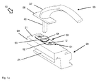
- actuating handle 10 is provided for the operation of a (not fully shown) window 20 having a frame or wings 22 and a known (not shown) transmission mechanism.
- the frame 22 has in the region of a stop surface 21 for the actuating handle 10, a first recess 23 which receives the actuating handle 10 at least partially, and a second recess 24 for the transmission mechanism.
- the first recess 23 and the second recess 24 are connected to each other via a perpendicular to the stop surface 21 extending bore 25.
- the actuating handle 10 has a handle 30 with a handle main part 31 and a handle neck 32, the front side has a flat end face 35 and a recess 34 introduced therein.
- a polygon 40 is fixed, preferably a square pin, which projects through the bore 25 in the frame 22 for actuating the integrated in the window 20 gear mechanism.
- a stopper 50 which is at least partially inserted into the first recess 23 of the frame 22 and secured by screws 12 to the window 20 and the frame 22, has an opening 64 centrally rotatably receiving the handle neck 32 of the handle 30. Over the opening 64, a cylindrical neck portion 65 is formed, which forms a pivot bearing for the handle neck 32 together with the opening 64.
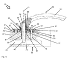
- the handle 30 On the polygon 40 is rotatably seated a locking disk 80 which rests with a side surface 81 on the end face 35 of the handle neck 32.
- the axial fixing of the handle 30 on the stopper body 50 is effected by a fixing element 90, which at the same time also secures the detent disk 80 axially on the polygon 40.
- the handle 30 is permanently stable and precisely rotatably mounted in the stopper body 50 and fixed in the axial direction L.
- the locking disk 80 has a center to the polygonal cross-section 40 in the same shape recess 82. It also has circumferentially formed locking recesses 84 which cooperate with locking elements 74 in the stopper body 50 and the handle 30 in excellent rotational positions, in particular in functional positions of the gear mechanism of the window 20, lock relative to the stopper body 50.
- two locking elements 74 are provided, which are arranged opposite one another in the stopper body 50.
- four locking recesses 84 are formed at intervals of 90 °.
- the fixing element 90 is preferably a serrated ring having inwardly directed serrations (not shown) in its central recess (not shown). These are designed and aligned such that the insertion of the polygon 40 in the serrated ring 90 in a first direction R1 is effected and locked in the opposite direction R2, i. the prongs slide during the assembly of the handle 30 in the direction of R1 along the side surfaces of the polygon 40 along.
- the teeth of the serrated ring 90 force, form and / or frictionally engage in the side surfaces of the polygon 40, so that Pulling out of the polygon 40 from the serrated ring 90 and thus a withdrawal of the handle 30 is effectively prevented by the stopper body 50 in the direction R2.
- the fixing element 90 is non-positively and / or positively connected to the locking disk 80.
- Fig. 1c shows - in the locking disc 80 concentric with the square recess 82 a (unspecified) recess provided, in which the fixing element 90 is inserted.
- a (not shown) against rotation is formed between the locking disc 80 and the fixing element 90.
- the latter is important so that the fixing element 90 and the locking disc 80 do not rotate each other when the handle 30 is actuated.
- the locking disc 80 and the fixing member 90 also preferably form a preassembled unit that can be handled and assembled quickly and easily.
- the fixing element 90 is bonded cohesively with the locking disk.
- the fixing element 90 and the locking disk 80 can also be formed in one piece.
- the handle neck 32 is secured by means of the locking disk 80 in or on the stopper body 50 by the locking disk 80 itself via an integrated fixing element 90 is positively, positively, and / or frictionally connected to the polygon 40.
- the locking disc 80 and / or the fixing element 90 can be integrally connected to the polygon 40.
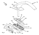
- a pivotable cover plate 58 is arranged above the stopper body 50. This is for this purpose provided with a (not designated) central recess. This allows the stopper body 50 and the screws 12 after installation of the actuating handle 10th are completely obscured at the window 20, resulting in an overall pleasing visual appearance.
- the stopper body 50 of the actuating handle 10 is - in particular the Fig. 1b shows - split. He has a lower part 51 and an upper part 61, which - depending on the embodiment - force, form and / or frictionally connected to each other. If necessary, lower part 51 and upper part 61 can also be releasably connected to one another.
- the lower part 51 has a base body 52, which is formed by three sections 511, 512, 513.
- Each section 511, 512, 513 is substantially circular in plan view, wherein the sections 511, 512, 513 in the edge regions overlap like circles, so that the overall shape of the lower part 51 in the plan view approximately corresponds to an elongated oval, the is constricted laterally in two places.
- the two outer sections 511, 513 are formed higher than the middle section 512, which essentially forms a flat disc with a support or support surface 72 for the locking disc 80.
- the outer diameter of the central portion 512 and the outer diameter of the locking disk 80 are about the same size.
- the total height of locking disk 80 and middle section 512 corresponds - as in Fig.
- each spring bar 73 extends transversely to the longitudinal axis of the main body 52 and transversely to the axial direction L.
- each spring web 73 carries on its middle section 512 and the locking disk 80 side facing one of the locking elements 74, which cooperate with the peripheral locking recesses 84 of the locking disc 80. It can be seen that the spring webs 73 and the latching elements 74 designed as projecting latching noses lie diametrically opposite each other and are preferably formed integrally with the main body 51.
- the central portion 512 of the body 52 is centrally provided with an opening 54 which is concentric with the bore 25 in the frame 22 and the polygon 40 rotatably receives.
- a shaft 55 is formed, which with slight movement play in the bore 25 in the frame 22 between the first recess 23 and the second recess 24 extends into it.
- the entire base body 52 and thus the lower part 51 of the stopper body 50 is inserted into the first recess 23 of the frame 22, wherein the side surface 81 of the locking disc 80 and the tops of the outer portions 511, 513 as an approximately flat surface is substantially flush complete with the stop surface 21 of the frame 22.
- the main body 51 can also rest on the (not further described) bottom of the first recess 23.
- the outer contour of the lower part 51 is adapted to the inner contour of the recess 23, which is preferably formed by three bores 26 arranged next to one another and partially overlapping. These can be - as well as the bore 25 - easily and efficiently bring into the frame 22, which has a favorable effect on the production costs of the window 20. In any case, no special tools or complex milling process are necessary to produce the recess 23.
- the lower part 51 formed by the three sections 511, 512, 513 can be manufactured simply and efficiently as a one-piece plastic part, together with the spring webs 73 and the shaft 55. It is completely sunk in the frame 22, which is extremely favorable for the visual appearance of the actuating handle 10 effects.
- the upper part 61 of the stopper body 50 has a base body 62 in the form of a flat plate, which is slightly larger in length and width than the main body 52 of the lower part 51.
- the recess 64 is formed centrally, the handle neck 32 of the handle 30th rotatably accommodates.
- the cylindrical neck portion 65 Over the recess 64 is the cylindrical neck portion 65, which is preferably integral with the base body 62 and forms together with the recess 64, the pivot bearing for the handle neck 32.
- the upper part 61 of the stopper body 50 lies flat on the lower part 51 of the stopper body 50, in particular, the base body 62 lies flat on the flat surface formed by the side surface 81 of the locking disk 80 and the upper sides of the outer portions 511, 513.
- the upper part 61 is after assembly of the stopper body 50 in the frame 22 with a peripheral edge on the stop surface 21 of the frame 22, so that the stopper body 50 finds an optimal support on the window 20 and the optical height of the actuating handle 10 to a minimum is reduced.
- the lower part 51 In order to connect the lower part 51 and the upper part 61 of the stopper body with each other, the lower part 51 at least a first connecting element 53, while the Upper part 61 is provided with at least one second connecting element 63. Both connecting elements 53, 63 are in pairs force, form and / or frictionally engageable with each other.
- the lower part 51 is provided with two first connecting elements 53, which are formed as cylindrical bushes. This is particularly advantageous because a simple and cost-effective production of the lower part 51 is possible.
- the first connecting elements or bushes 53 are formed in the outer sections 511, 513 of the main body 52. They are symmetrical to the middle section 512 and to the opening 54.
- Each second connecting element 63 on the upper part 61 is formed complementary to the respective first connecting element 53 of the lower part 51.
- the second connection element 63 is e.g. around a cylindrical collar whose outer diameter is slightly larger than the inner diameter of a cylindrical bushing of the first connecting element 53, whereby the lower part 51 and the upper part 61 can be positively and frictionally engaged with each other.
- Each collar 63 is located below a passage opening 67 in the main body 62 of the upper part 61, wherein the two passage openings 67 are arranged symmetrically to the opening 64 and the neck portion 65 of the upper part 61.
- first and second connecting elements 53, 63 advantageously form two plug-socket pairs, which connect the lower part 51 and the upper part 61 fixedly but detachably.
- a further advantage is that the connecting elements 53, 63 of the lower part 51 and upper part 61 together with the through holes 57, 67 receive the screws 12 which are provided for fixing the stopper body 50 on the frame 22 of the window 20. In the assembled position of the stopper body 50, the screws 12 therefore additionally secure the connection between the lower part 51 and the upper part 61.
- the lower part 51 and the upper part 61 of the stopper body 50 are designed such that they Detaching disc 80 between them, especially if this rests between the outer portions 511, 513 of the base body 52 on the support surface 72 of the central portion 512 and is covered by the plate-shaped base body 62 of the upper part 61.
- the fixing member 90 on the polygon 40 axially secured and supported by the central portion 512 locking disk 80 is supported with its side surface 81 on the underside of the upper part 61 and on the end face 35 of the handle neck 32. This results in a very stable storage for the handle 30 on the stopper body 50 and an extremely stable Installation situation of the actuating handle 10, which easily withstands even extremely high and permanent loads.
- the locking disk 80 with the integrated therein serrated ring 90 is inserted into the lower part 51 and positioned between the spring webs 73. Subsequently, the upper part 61 is placed on the lower part 51, wherein the connecting elements 53, 63 intermesh. If the upper part 61 flat on the outer portions 511, 513 of the lower part 51 and the side surface 81 of the locking disc 80, the latter is stable and securely mounted on the support surface.
- the stopper body 50 is preassembled as described above, this is inserted into the first recess 23 of the frame 22 and fixed with the screws 12 therein. The latter enforce the connecting elements 53, 63 and at the same time fix the upper part 61 on the support surface 21 of the frame 22. Thereafter, the cover plate 58 is placed with its central recess on the neck portion 65 of the upper part 61, then the handle 30 with the handle neck in the 32nd pre-assembled polygon 40 to assemble.
- the serrated ring 90 ensures a permanently reliable axial fixation of the handle 30 on the stop body 50.
- a fitting fuse 100 is arranged.
- a fitting is used for example as a child safety, because the operation of the handle 30 is dependent on the correct and complete operation of the fitting fuse 100, ie only when the fitting fuse 100 is properly operated, a rotation of the handle 30 in another functional position is possible.
- the handle 30 and the stopper body 50 with lower part 51 and upper part 61 are designed as described above. In that regard, like reference numerals always refer to the same components.
- the fitting fuse 100 has a comparison with the cover 58 pleasantkontur Sammlunge, relatively flat console 105, are mounted longitudinally displaceable in the two locking elements 101. These are to set the handle 30 in an excellent rotational position, with a non-rotatably seated on the polygon 40 locking disk 104 into engagement. To release the lock can the locking elements 101 against a spring force on externally accessible actuators 102 disengage from the locking disc 104, so that the handle 30 can be actuated to open or close the window 20 (see Fig. 2a and 2 B ).
- the substantially rectangular console 105 has a flat bottom with a (not visible) center hole and two elongated side walls 115. At its two narrow sides, the console 105 is formed open. Symmetrical to the center hole and aligned on a longitudinal axis are two in each case penetrated by a through hole 109 ring bushes 119, which serve to pass through the connecting elements 63 of the upper part 61 and thus for carrying out the screws 12.
- the ring bushings 119 preferably have the same height as the side walls 115.
- two flat slides 103 are mounted side by side and in opposite directions sliding, which are designed substantially L-shaped, each with an elongated side part and a transverse elbow.
- a locking element 101 is formed centrally to the longitudinal axis, and as a nose or bevel out of the surface of the slide out.
- the locking elements 101 are for fixing the handle 30 with the non-rotatably mounted on the polygon 40 locking disk 104 is engaged, which has two mutually opposite recesses. Their shape is opposite to the locking elements 101 of the slide.
- the locking disc 104 has a square hole 114 for positive reception of the polygon 40, which is further preferably designed as a square pin.
- two springs 120 are provided (see also Fig. 3 ), which are respectively supported on a side part and a curved portion of the slider. Both have flat support surfaces, which are perpendicular to the longitudinal axis of the console 105.
- the actuators 102 are thus always in a stable position, the locking elements 101 of each slider 103 are engaged in a recess of the locking disc 104, so that the handle 30 is not rotated and the window 20 can not be opened.
- the locking elements 101 secure the slides 103 within the console 105.
- the actuating elements 102 are provided, which are approximately U-shaped and parallel to the longitudinal axis of the Console formed 105 thighs in the open narrow sides of the console 105 are used. Two leg pieces connecting bow pieces 112 project as a handle out of the console 105. These overlap the cross pieces of the slide 103 positively, while the U-legs rest flat on the sliders 103.
- one leg of the actuating elements 102 is provided with an elongate recess 121. In these recesses 121, the springs 120 are used so that they receive a precise guide. At the same time the actuators 102 are secured against falling out in the longitudinal direction.
- the outer shape of the curved pieces 112 of the actuating elements 102 is preferably adapted to the outer contour of the console 105, so that the fitting fuse 100 and thus the actuating handle 10 'receives an overall uniform and aesthetically pleasing appearance.
- the actuating elements 102 are pushed into the bracket 105 on both sides, then the arched portions 112 projecting outwards slide the slides 103 substantially synchronously inwards over the transverse pieces.
- the springs 120 are compressed between the support surfaces and the locking elements 101 are lifted out of the locking disk 104.
- the handle 30 can now rotate freely, so that its polygon 40, the locking disk 80 and the transmission mechanism in the window 20 can rotate. Letting the actuators 102 and the arched pieces 112 go, the locking elements 101 can slide along the circumference of the locking disc 104 until the opposite recesses approach and the locking elements 101 coincide at the same time, as a result of which the handle rotation is again locked.
- a cover plate 106 is provided, which can be latched with lateral latching edges in the side walls 115 of the console 105.
- the latter is provided on the edge side with corresponding locking grooves.
- a central opening 107 in the cover plate 106 is concentric with the center hole in the console 105 and also concentric with the opening 64 in the top 61. With two other side openings the cover plate 106 is fitted to the ring bushings 119, which the stability of the console 105 and thus the Fuse 100 further enlarged.
- An advantage of the described fitting fuse 100 is that it is point-symmetrical with respect to the axis of rotation of the handle 30. All components are also identically designed so that they can be interchanged. This causes a significant reduction in manufacturing and storage costs.
- a blocking or locking is provided every 180 °.
- the locking disc 104 can be provided with three or four circumferential recesses, so that the handle 30 on the window 20 is latched every 90 ° with the securing mechanism 100. This consists of a total of a few components, which are all formed very flat and thus hardly affect the appearance of the recessed in the window frame 22 actuating handle 10 '. Also, the elbows 112 of the actuators 102 protrude only slightly from the console 105, which has a favorable effect on the appearance. In addition, no sweeping movements are necessary for the operation.
- the fitting fuse 100 also forms a preassembled unit that can not only be prefabricated quickly and inexpensively. It can rather be installed quickly and conveniently between the lower part 51 and the upper part 61 of the stopper body 50.
- 63 latching elements 66 are formed in the form of expansion legs on the underside of the connecting elements, which come into engagement with the connecting elements 53 of the lower part 51.
- the connecting elements 53 have corresponding counter-latches 56 for this purpose.
- Fig. 2b 2 shows two hollow cylindrical cams 129 are formed on the underside of the bracket 105 in the region of the two through holes 109, which engage in the base body 52 of the lower part 51 in the region of the counter-latches 56.
- the fitting fuse 100 and the lower part 51 are positively and frictionally engaged with each other, so that an always accurate and stable positioning of the fitting fuse 100 is guaranteed.
- the cams 129 secure the counter-latches 56, so that the upper part 61 is always firmly connected to the lower part 51.
- the console 105 may be formed substantially smooth at the bottom, because by the sandwich-like arrangement, ie the arrangement of the fitting fuse 100 between the lower part 51 and the upper part 61, and in that the lower part 51 and the upper part 61 by the locking elements 66 and the counter-latches 56 are brought through the ring bushings 119 of the console 105 are engaged with each other, already a sufficiently high stability is achieved.
- Fig. 2c shows the installation situation of the actuating handle 10 'according to Fig. 2 in cross section.
- actuating handle 10 'according to the invention and the associated fitting fuse 100 Another advantage of the actuating handle 10 'according to the invention and the associated fitting fuse 100 is that existing actuating handles 10 can be retrofitted without changes being made to the fitting have to.
- actuating handle 10 Another significant advantage of the actuating handle 10 'according to the invention is that the fitting fuse 100 in the sandwich arrangement is an integral part of the stopper body 50 and that the console 105 of the fitting fuse 100 rests in the mounted state on the stop surface 21 of the frame 22, while the entire lower part 51 of the stopper body 50 in the frame 22 disappears.
- the console 105 of the fitting fuse 100 rests in the mounted state on the stop surface 21 of the frame 22, while the entire lower part 51 of the stopper body 50 in the frame 22 disappears.
- the locking disk 80 with the integrated serrated ring 90 is first inserted into the lower part 51 and positioned between the spring webs 73. Thereafter, the fitting fuse 100 is placed on the lower part 51, wherein the console 105 rests flat with its underside on the outer portions 511, 513 of the lower part 51 and the side surface 81 of the locking disk 80. Subsequently, the upper part 61 is attached to the fitting fuse 100, wherein the connecting elements 63 of the upper part 61 protrude through the ring bushes 119 and the through holes 109 in the console 105 and engage with the connecting elements 53 of the lower part 51 in engagement. The upper part 61 is now flat on the cover plate 106 of the fitting fuse 100. The latter is stable and securely mounted on the stop surface 21 of the frame 22.
- the stopper body 50 is preassembled as described above together with the fitting fuse 100, the stopper body 50 is inserted with the lower part 51 in the first recess 23 of the frame 22 and fixed with the screws 12 therein. The latter enforce the connecting elements 53, 63 and the ring bushes 119 and at the same time fix the fitting fuse 100 on the stop surface 21 of the frame 22. Thereafter, the cover plate 58 is placed with its central recess on the neck portion 65 of the upper part 61, then the handle 30 with the pre-assembled in the handle neck 32 polygon 40 to assemble.
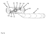
- the cover plate 106 of the bracket 105 of the fitting fuse 100 is formed as a top 61 for the stopper body 50.
- the neck portion 65 here additionally has two diametrically opposite recesses 107 for the locking elements 101 of the fitting fuse 100.
- Fig. 3 . 3a and 3b further show an alternative embodiment of the locking elements 74, which are formed here as balls. These sit in the lower part 51 of the stopper body 50 in longitudinal slots 130, which are formed in the outer or lateral portions 511,513 of the main body 52. Within each longitudinal slot 130 is a compression spring 132, which presses the balls 74 radially against the locking disc 80.
- the invention is not limited to one of the above-described embodiments, but can be modified in many ways. So you can choose as a fixing 90 instead of a serrated ring and another fastening solution, such as a snap ring or a spring washer. It is also conceivable to use a locking connection or a Klemmgesperres.
- the radial locking of the locking disc 80 with the lower part 51 can - if the height allows - also be done axially if necessary, the locking would preferably be done with the central portion 512 of the lower part 51.
- the lower part 51 and the upper part 61 may be screwed separately or directly with the interposition of the fitting fuse 100. It is also possible that the upper part 61 with the fitting fuse 100 and this in turn with the lower part 51 force, form and / or frictionally connected.
- the invention provides an actuating handle for a window or a door, with a rotatably mounted handle and an adjoining handle neck, which has a recess on the front side, in which a polygon for actuating a trained in the window or in the door closing mechanism is fixed.
- the stop body of the actuating handle is fixed to or in the window or the door, wherein the handle neck of the Handle axially fixed-rotatably mounted in or on the stop body.
- the stopper body a lower part and a shell comprises, wherein between the lower part and the upper part of a locking disk is arranged, which has a center to the polygonal cross-section in the same shape recess, and wherein the lower and the upper part force, form and / or frictionally engaged with each other. It is further provided that between the lower part and the upper part of a fitting securing is arranged, which is preferably arranged as a preassembled unit sandwiched between the upper part and the lower part. In a further embodiment, the cover plate of the fitting securing can form the upper part of the actuating handle
Landscapes
- Engineering & Computer Science (AREA)
- Mechanical Engineering (AREA)
- Lock And Its Accessories (AREA)
- Mechanical Control Devices (AREA)
Applications Claiming Priority (1)
| Application Number | Priority Date | Filing Date | Title |
|---|---|---|---|
| DE102013112580.8A DE102013112580A1 (de) | 2013-11-14 | 2013-11-14 | Betätigungshandhabe |
Publications (3)
| Publication Number | Publication Date |
|---|---|
| EP2873787A2 true EP2873787A2 (fr) | 2015-05-20 |
| EP2873787A3 EP2873787A3 (fr) | 2015-09-30 |
| EP2873787B1 EP2873787B1 (fr) | 2020-03-18 |
Family
ID=51300644
Family Applications (1)
| Application Number | Title | Priority Date | Filing Date |
|---|---|---|---|
| EP14180618.2A Active EP2873787B1 (fr) | 2013-11-14 | 2014-08-12 | Poignée d'actionnement |
Country Status (2)
| Country | Link |
|---|---|
| EP (1) | EP2873787B1 (fr) |
| DE (1) | DE102013112580A1 (fr) |
Cited By (4)
| Publication number | Priority date | Publication date | Assignee | Title |
|---|---|---|---|---|
| EP3480393A1 (fr) * | 2017-11-06 | 2019-05-08 | MasterLAB S.r.l. - Unipersonale | Dispositif et procede de montage d'une poignee sur une porte ou une fenetre |
| IT201800004467A1 (it) * | 2018-04-13 | 2019-10-13 | Dispositivo di comando manuale della serratura di un serramento | |
| EP3575515A1 (fr) * | 2018-05-30 | 2019-12-04 | Jasa Company A/S | Poignée pour actionner une fenêtre ou une porte |
| CN117305109A (zh) * | 2023-10-28 | 2023-12-29 | 苏州环美生物医疗科技有限公司 | 一种振荡细胞克隆培养装置和组合式培养设备 |
Families Citing this family (1)
| Publication number | Priority date | Publication date | Assignee | Title |
|---|---|---|---|---|
| US20170298652A1 (en) * | 2016-04-18 | 2017-10-19 | Wan Lai Liau | Fix posistion device for casement latch |
Citations (2)
| Publication number | Priority date | Publication date | Assignee | Title |
|---|---|---|---|---|
| DE29922496U1 (de) | 1999-12-22 | 2000-03-30 | Hoppe Ag St Martin | Betätigungshandhabe |
| EP1528194A1 (fr) | 2003-10-28 | 2005-05-04 | Hoppe AG | Ferrure, notamment ferrure de fenêtre |
Family Cites Families (5)
| Publication number | Priority date | Publication date | Assignee | Title |
|---|---|---|---|---|
| DE3203311A1 (de) * | 1982-01-29 | 1983-08-11 | Fa. Aug. Winkhaus, 4404 Telgte | Griffbeschlag mit kindersicherung fuer fenster- oder tuerfluegel |
| DE29703607U1 (de) * | 1997-02-28 | 1997-04-24 | Hoppe Ag | Betätigungshandhabe |
| DE20011806U1 (de) * | 2000-07-07 | 2000-09-14 | Fsb Franz Schneider Brakel Gmb | Drehgriff |
| DE202007000380U1 (de) * | 2007-01-04 | 2008-05-15 | Hoppe Ag | Rückholfedereinrichtung für Tür- oder Fensterbeschläge sowie Tür- und/oder Fensterbeschlag |
| EP2034109B1 (fr) * | 2007-09-07 | 2016-10-05 | DORMA Deutschland GmbH | Rosette avec dispositif de sécurité |
-
2013
- 2013-11-14 DE DE102013112580.8A patent/DE102013112580A1/de not_active Ceased
-
2014
- 2014-08-12 EP EP14180618.2A patent/EP2873787B1/fr active Active
Patent Citations (2)
| Publication number | Priority date | Publication date | Assignee | Title |
|---|---|---|---|---|
| DE29922496U1 (de) | 1999-12-22 | 2000-03-30 | Hoppe Ag St Martin | Betätigungshandhabe |
| EP1528194A1 (fr) | 2003-10-28 | 2005-05-04 | Hoppe AG | Ferrure, notamment ferrure de fenêtre |
Cited By (7)
| Publication number | Priority date | Publication date | Assignee | Title |
|---|---|---|---|---|
| EP3480393A1 (fr) * | 2017-11-06 | 2019-05-08 | MasterLAB S.r.l. - Unipersonale | Dispositif et procede de montage d'une poignee sur une porte ou une fenetre |
| EP3792433A1 (fr) * | 2017-11-06 | 2021-03-17 | Masterlab S.R.L. | Dispositif et procédé de montage d'une poignée sur un battant de porte ou de fenêtre |
| IT201800004467A1 (it) * | 2018-04-13 | 2019-10-13 | Dispositivo di comando manuale della serratura di un serramento | |
| WO2019197523A1 (fr) * | 2018-04-13 | 2019-10-17 | Opentech S.R.L. A Socio Unico | Dispositif de commande manuelle d'un verrou de porte ou de fenêtre |
| EP3575515A1 (fr) * | 2018-05-30 | 2019-12-04 | Jasa Company A/S | Poignée pour actionner une fenêtre ou une porte |
| CN117305109A (zh) * | 2023-10-28 | 2023-12-29 | 苏州环美生物医疗科技有限公司 | 一种振荡细胞克隆培养装置和组合式培养设备 |
| CN117305109B (zh) * | 2023-10-28 | 2024-03-12 | 苏州环美生物医疗科技有限公司 | 一种振荡细胞克隆培养装置和组合式培养设备 |
Also Published As
| Publication number | Publication date |
|---|---|
| EP2873787B1 (fr) | 2020-03-18 |
| EP2873787A3 (fr) | 2015-09-30 |
| DE102013112580A1 (de) | 2015-05-21 |
Similar Documents
| Publication | Publication Date | Title |
|---|---|---|
| EP2193246B1 (fr) | Paire de poignées de commande de porte | |
| EP1290303B1 (fr) | Serrure a barres pour systeme de fermeture | |
| DE102011102159B4 (de) | Modularer Schließzylinder | |
| EP2924196B1 (fr) | Commande d'actionnement | |
| EP2182144B1 (fr) | Rebord de porte ou de fenêtre | |
| EP2873787B1 (fr) | Poignée d'actionnement | |
| EP2924197A2 (fr) | Corps de butée pour poignées de porte et/ou de fenêtre | |
| EP2476823A2 (fr) | Poignée d'actionnement | |
| EP3336284B1 (fr) | Corps de butée pour poignée d'actionnement, poignée d'actionnement et porte | |
| WO2016128267A1 (fr) | Mâchoire de serrage destinée à être montée sur une glissière d'une table d'opération | |
| EP2107189B1 (fr) | Armature pour fenêtres ou portes | |
| EP2924195A1 (fr) | Corps de butée pour poignée de fenêtre et/ou de porte et système de poignée doté d'un corps de butée | |
| EP0555633B1 (fr) | Garniture pour poignée de porte | |
| EP1528194B1 (fr) | Ferrure, notamment ferrure de fenêtre | |
| EP2565351B1 (fr) | Agencement de poignée | |
| DE202006009023U1 (de) | Band mit verbesserter Justierung | |
| EP3486407B1 (fr) | Élément de poignée et garniture de poignée de fenêtre | |
| EP3498941A1 (fr) | Élément d'actionnement pourvu d'un dispositif de verrouillage | |
| EP1152106B1 (fr) | Poignée de commande | |
| EP3363969A1 (fr) | Poignée d'actionnement | |
| EP1793067B1 (fr) | Ferrure pour portes, fenêtres ou similaires | |
| DE102013205061A1 (de) | Bedienungsmittel für eine Platte, Kombination zweier Bedienungsmittel und Verfahren zum klemmfesten Positionieren des Bedienungsmittels an einer Platte | |
| EP1321605B1 (fr) | Poignée d'actionnement | |
| EP1918492A2 (fr) | Ferrure pour la fixation d'une poignée sur une porte ou une fenêtre | |
| EP3626914A1 (fr) | Dispositif de rappel destiné à la manipulation d'une ferrure et procédé de transfert d'un dispositif de rappel entre une première position de manipulation et une seconde position de manipulation |
Legal Events
| Date | Code | Title | Description |
|---|---|---|---|
| PUAI | Public reference made under article 153(3) epc to a published international application that has entered the european phase |
Free format text: ORIGINAL CODE: 0009012 |
|
| 17P | Request for examination filed |
Effective date: 20140812 |
|
| AK | Designated contracting states |
Kind code of ref document: A2 Designated state(s): AL AT BE BG CH CY CZ DE DK EE ES FI FR GB GR HR HU IE IS IT LI LT LU LV MC MK MT NL NO PL PT RO RS SE SI SK SM TR |
|
| AX | Request for extension of the european patent |
Extension state: BA ME |
|
| PUAL | Search report despatched |
Free format text: ORIGINAL CODE: 0009013 |
|
| AK | Designated contracting states |
Kind code of ref document: A3 Designated state(s): AL AT BE BG CH CY CZ DE DK EE ES FI FR GB GR HR HU IE IS IT LI LT LU LV MC MK MT NL NO PL PT RO RS SE SI SK SM TR |
|
| AX | Request for extension of the european patent |
Extension state: BA ME |
|
| RIC1 | Information provided on ipc code assigned before grant |
Ipc: E05B 13/00 20060101ALI20150827BHEP Ipc: E05B 3/06 20060101AFI20150827BHEP |
|
| R17P | Request for examination filed (corrected) |
Effective date: 20160322 |
|
| RAX | Requested extension states of the european patent have changed |
Extension state: ME Payment date: 20160322 Extension state: BA Payment date: 20160322 |
|
| RBV | Designated contracting states (corrected) |
Designated state(s): AL AT BE BG CH CY CZ DE DK EE ES FI FR GB GR HR HU IE IS IT LI LT LU LV MC MK MT NL NO PL PT RO RS SE SI SK SM TR |
|
| RAP1 | Party data changed (applicant data changed or rights of an application transferred) |
Owner name: HOPPE AG |
|
| STAA | Information on the status of an ep patent application or granted ep patent |
Free format text: STATUS: EXAMINATION IS IN PROGRESS |
|
| 17Q | First examination report despatched |
Effective date: 20181015 |
|
| GRAP | Despatch of communication of intention to grant a patent |
Free format text: ORIGINAL CODE: EPIDOSNIGR1 |
|
| STAA | Information on the status of an ep patent application or granted ep patent |
Free format text: STATUS: GRANT OF PATENT IS INTENDED |
|
| RIC1 | Information provided on ipc code assigned before grant |
Ipc: E05B 1/00 20060101ALI20190401BHEP Ipc: E05B 15/00 20060101ALI20190401BHEP Ipc: E05B 3/06 20060101AFI20190401BHEP Ipc: E05B 65/00 20060101ALI20190401BHEP Ipc: E05B 13/00 20060101ALI20190401BHEP |
|
| INTG | Intention to grant announced |
Effective date: 20190429 |
|
| GRAJ | Information related to disapproval of communication of intention to grant by the applicant or resumption of examination proceedings by the epo deleted |
Free format text: ORIGINAL CODE: EPIDOSDIGR1 |
|
| STAA | Information on the status of an ep patent application or granted ep patent |
Free format text: STATUS: EXAMINATION IS IN PROGRESS |
|
| GRAP | Despatch of communication of intention to grant a patent |
Free format text: ORIGINAL CODE: EPIDOSNIGR1 |
|
| STAA | Information on the status of an ep patent application or granted ep patent |
Free format text: STATUS: GRANT OF PATENT IS INTENDED |
|
| INTC | Intention to grant announced (deleted) | ||
| INTG | Intention to grant announced |
Effective date: 20191004 |
|
| GRAS | Grant fee paid |
Free format text: ORIGINAL CODE: EPIDOSNIGR3 |
|
| GRAA | (expected) grant |
Free format text: ORIGINAL CODE: 0009210 |
|
| STAA | Information on the status of an ep patent application or granted ep patent |
Free format text: STATUS: THE PATENT HAS BEEN GRANTED |
|
| AK | Designated contracting states |
Kind code of ref document: B1 Designated state(s): AL AT BE BG CH CY CZ DE DK EE ES FI FR GB GR HR HU IE IS IT LI LT LU LV MC MK MT NL NO PL PT RO RS SE SI SK SM TR |
|
| AX | Request for extension of the european patent |
Extension state: BA ME |
|
| REG | Reference to a national code |
Ref country code: GB Ref legal event code: FG4D Free format text: NOT ENGLISH |
|
| REG | Reference to a national code |
Ref country code: DE Ref legal event code: R096 Ref document number: 502014013807 Country of ref document: DE |
|
| REG | Reference to a national code |
Ref country code: AT Ref legal event code: REF Ref document number: 1246063 Country of ref document: AT Kind code of ref document: T Effective date: 20200415 Ref country code: IE Ref legal event code: FG4D Free format text: LANGUAGE OF EP DOCUMENT: GERMAN |
|
| REG | Reference to a national code |
Ref country code: NL Ref legal event code: FP |
|
| REG | Reference to a national code |
Ref country code: SE Ref legal event code: TRGR |
|
| PG25 | Lapsed in a contracting state [announced via postgrant information from national office to epo] |
Ref country code: RS Free format text: LAPSE BECAUSE OF FAILURE TO SUBMIT A TRANSLATION OF THE DESCRIPTION OR TO PAY THE FEE WITHIN THE PRESCRIBED TIME-LIMIT Effective date: 20200318 Ref country code: NO Free format text: LAPSE BECAUSE OF FAILURE TO SUBMIT A TRANSLATION OF THE DESCRIPTION OR TO PAY THE FEE WITHIN THE PRESCRIBED TIME-LIMIT Effective date: 20200618 Ref country code: FI Free format text: LAPSE BECAUSE OF FAILURE TO SUBMIT A TRANSLATION OF THE DESCRIPTION OR TO PAY THE FEE WITHIN THE PRESCRIBED TIME-LIMIT Effective date: 20200318 |
|
| PG25 | Lapsed in a contracting state [announced via postgrant information from national office to epo] |
Ref country code: BG Free format text: LAPSE BECAUSE OF FAILURE TO SUBMIT A TRANSLATION OF THE DESCRIPTION OR TO PAY THE FEE WITHIN THE PRESCRIBED TIME-LIMIT Effective date: 20200618 Ref country code: LV Free format text: LAPSE BECAUSE OF FAILURE TO SUBMIT A TRANSLATION OF THE DESCRIPTION OR TO PAY THE FEE WITHIN THE PRESCRIBED TIME-LIMIT Effective date: 20200318 Ref country code: HR Free format text: LAPSE BECAUSE OF FAILURE TO SUBMIT A TRANSLATION OF THE DESCRIPTION OR TO PAY THE FEE WITHIN THE PRESCRIBED TIME-LIMIT Effective date: 20200318 Ref country code: GR Free format text: LAPSE BECAUSE OF FAILURE TO SUBMIT A TRANSLATION OF THE DESCRIPTION OR TO PAY THE FEE WITHIN THE PRESCRIBED TIME-LIMIT Effective date: 20200619 |
|
| REG | Reference to a national code |
Ref country code: LT Ref legal event code: MG4D |
|
| PG25 | Lapsed in a contracting state [announced via postgrant information from national office to epo] |
Ref country code: EE Free format text: LAPSE BECAUSE OF FAILURE TO SUBMIT A TRANSLATION OF THE DESCRIPTION OR TO PAY THE FEE WITHIN THE PRESCRIBED TIME-LIMIT Effective date: 20200318 Ref country code: PT Free format text: LAPSE BECAUSE OF FAILURE TO SUBMIT A TRANSLATION OF THE DESCRIPTION OR TO PAY THE FEE WITHIN THE PRESCRIBED TIME-LIMIT Effective date: 20200812 Ref country code: SM Free format text: LAPSE BECAUSE OF FAILURE TO SUBMIT A TRANSLATION OF THE DESCRIPTION OR TO PAY THE FEE WITHIN THE PRESCRIBED TIME-LIMIT Effective date: 20200318 Ref country code: SK Free format text: LAPSE BECAUSE OF FAILURE TO SUBMIT A TRANSLATION OF THE DESCRIPTION OR TO PAY THE FEE WITHIN THE PRESCRIBED TIME-LIMIT Effective date: 20200318 Ref country code: CZ Free format text: LAPSE BECAUSE OF FAILURE TO SUBMIT A TRANSLATION OF THE DESCRIPTION OR TO PAY THE FEE WITHIN THE PRESCRIBED TIME-LIMIT Effective date: 20200318 Ref country code: IS Free format text: LAPSE BECAUSE OF FAILURE TO SUBMIT A TRANSLATION OF THE DESCRIPTION OR TO PAY THE FEE WITHIN THE PRESCRIBED TIME-LIMIT Effective date: 20200718 Ref country code: RO Free format text: LAPSE BECAUSE OF FAILURE TO SUBMIT A TRANSLATION OF THE DESCRIPTION OR TO PAY THE FEE WITHIN THE PRESCRIBED TIME-LIMIT Effective date: 20200318 Ref country code: LT Free format text: LAPSE BECAUSE OF FAILURE TO SUBMIT A TRANSLATION OF THE DESCRIPTION OR TO PAY THE FEE WITHIN THE PRESCRIBED TIME-LIMIT Effective date: 20200318 |
|
| PGFP | Annual fee paid to national office [announced via postgrant information from national office to epo] |
Ref country code: NL Payment date: 20200826 Year of fee payment: 7 Ref country code: DE Payment date: 20200831 Year of fee payment: 7 |
|
| REG | Reference to a national code |
Ref country code: DE Ref legal event code: R097 Ref document number: 502014013807 Country of ref document: DE |
|
| PLBE | No opposition filed within time limit |
Free format text: ORIGINAL CODE: 0009261 |
|
| STAA | Information on the status of an ep patent application or granted ep patent |
Free format text: STATUS: NO OPPOSITION FILED WITHIN TIME LIMIT |
|
| PG25 | Lapsed in a contracting state [announced via postgrant information from national office to epo] |
Ref country code: IT Free format text: LAPSE BECAUSE OF FAILURE TO SUBMIT A TRANSLATION OF THE DESCRIPTION OR TO PAY THE FEE WITHIN THE PRESCRIBED TIME-LIMIT Effective date: 20200318 Ref country code: DK Free format text: LAPSE BECAUSE OF FAILURE TO SUBMIT A TRANSLATION OF THE DESCRIPTION OR TO PAY THE FEE WITHIN THE PRESCRIBED TIME-LIMIT Effective date: 20200318 Ref country code: ES Free format text: LAPSE BECAUSE OF FAILURE TO SUBMIT A TRANSLATION OF THE DESCRIPTION OR TO PAY THE FEE WITHIN THE PRESCRIBED TIME-LIMIT Effective date: 20200318 |
|
| 26N | No opposition filed |
Effective date: 20201221 |
|
| PG25 | Lapsed in a contracting state [announced via postgrant information from national office to epo] |
Ref country code: PL Free format text: LAPSE BECAUSE OF FAILURE TO SUBMIT A TRANSLATION OF THE DESCRIPTION OR TO PAY THE FEE WITHIN THE PRESCRIBED TIME-LIMIT Effective date: 20200318 |
|
| PG25 | Lapsed in a contracting state [announced via postgrant information from national office to epo] |
Ref country code: MC Free format text: LAPSE BECAUSE OF FAILURE TO SUBMIT A TRANSLATION OF THE DESCRIPTION OR TO PAY THE FEE WITHIN THE PRESCRIBED TIME-LIMIT Effective date: 20200318 |
|
| REG | Reference to a national code |
Ref country code: CH Ref legal event code: PL |
|
| GBPC | Gb: european patent ceased through non-payment of renewal fee |
Effective date: 20200812 |
|
| PG25 | Lapsed in a contracting state [announced via postgrant information from national office to epo] |
Ref country code: CH Free format text: LAPSE BECAUSE OF NON-PAYMENT OF DUE FEES Effective date: 20200831 Ref country code: LI Free format text: LAPSE BECAUSE OF NON-PAYMENT OF DUE FEES Effective date: 20200831 Ref country code: LU Free format text: LAPSE BECAUSE OF NON-PAYMENT OF DUE FEES Effective date: 20200812 |
|
| REG | Reference to a national code |
Ref country code: BE Ref legal event code: MM Effective date: 20200831 |
|
| PG25 | Lapsed in a contracting state [announced via postgrant information from national office to epo] |
Ref country code: SI Free format text: LAPSE BECAUSE OF FAILURE TO SUBMIT A TRANSLATION OF THE DESCRIPTION OR TO PAY THE FEE WITHIN THE PRESCRIBED TIME-LIMIT Effective date: 20200318 |
|
| PG25 | Lapsed in a contracting state [announced via postgrant information from national office to epo] |
Ref country code: FR Free format text: LAPSE BECAUSE OF NON-PAYMENT OF DUE FEES Effective date: 20200831 |
|
| PG25 | Lapsed in a contracting state [announced via postgrant information from national office to epo] |
Ref country code: GB Free format text: LAPSE BECAUSE OF NON-PAYMENT OF DUE FEES Effective date: 20200812 Ref country code: IE Free format text: LAPSE BECAUSE OF NON-PAYMENT OF DUE FEES Effective date: 20200812 Ref country code: BE Free format text: LAPSE BECAUSE OF NON-PAYMENT OF DUE FEES Effective date: 20200831 |
|
| REG | Reference to a national code |
Ref country code: AT Ref legal event code: MM01 Ref document number: 1246063 Country of ref document: AT Kind code of ref document: T Effective date: 20200812 |
|
| PG25 | Lapsed in a contracting state [announced via postgrant information from national office to epo] |
Ref country code: AT Free format text: LAPSE BECAUSE OF NON-PAYMENT OF DUE FEES Effective date: 20200812 |
|
| REG | Reference to a national code |
Ref country code: DE Ref legal event code: R119 Ref document number: 502014013807 Country of ref document: DE |
|
| REG | Reference to a national code |
Ref country code: NL Ref legal event code: MM Effective date: 20210901 |
|
| PG25 | Lapsed in a contracting state [announced via postgrant information from national office to epo] |
Ref country code: TR Free format text: LAPSE BECAUSE OF FAILURE TO SUBMIT A TRANSLATION OF THE DESCRIPTION OR TO PAY THE FEE WITHIN THE PRESCRIBED TIME-LIMIT Effective date: 20200318 Ref country code: MT Free format text: LAPSE BECAUSE OF FAILURE TO SUBMIT A TRANSLATION OF THE DESCRIPTION OR TO PAY THE FEE WITHIN THE PRESCRIBED TIME-LIMIT Effective date: 20200318 Ref country code: CY Free format text: LAPSE BECAUSE OF FAILURE TO SUBMIT A TRANSLATION OF THE DESCRIPTION OR TO PAY THE FEE WITHIN THE PRESCRIBED TIME-LIMIT Effective date: 20200318 |
|
| PG25 | Lapsed in a contracting state [announced via postgrant information from national office to epo] |
Ref country code: NL Free format text: LAPSE BECAUSE OF NON-PAYMENT OF DUE FEES Effective date: 20210901 Ref country code: MK Free format text: LAPSE BECAUSE OF FAILURE TO SUBMIT A TRANSLATION OF THE DESCRIPTION OR TO PAY THE FEE WITHIN THE PRESCRIBED TIME-LIMIT Effective date: 20200318 Ref country code: AL Free format text: LAPSE BECAUSE OF FAILURE TO SUBMIT A TRANSLATION OF THE DESCRIPTION OR TO PAY THE FEE WITHIN THE PRESCRIBED TIME-LIMIT Effective date: 20200318 |
|
| PG25 | Lapsed in a contracting state [announced via postgrant information from national office to epo] |
Ref country code: DE Free format text: LAPSE BECAUSE OF NON-PAYMENT OF DUE FEES Effective date: 20220301 |
|
| PGFP | Annual fee paid to national office [announced via postgrant information from national office to epo] |
Ref country code: SE Payment date: 20230830 Year of fee payment: 10 |